clock ISUZU KB P190 2007 Workshop Owner's Guide
[x] Cancel search | Manufacturer: ISUZU, Model Year: 2007, Model line: KB P190, Model: ISUZU KB P190 2007Pages: 6020, PDF Size: 70.23 MB
Page 2575 of 6020
Engine Mechanical – V6 Page 6A1–96
Remove
Right-hand Secondary Timing Chain
CAUTION
After removing the upper intake manifold, and
spark plugs, plug any openings to prevent dirt
and other contaminants from entering.
1 Remove the engine front cover assembly, refer to 3.15 Front Cover Assembly.
2 Remove the spark plugs to aid crankshaft/engine rotation, refer to 6C1-3 Engine Management – V6 – Service Operations.
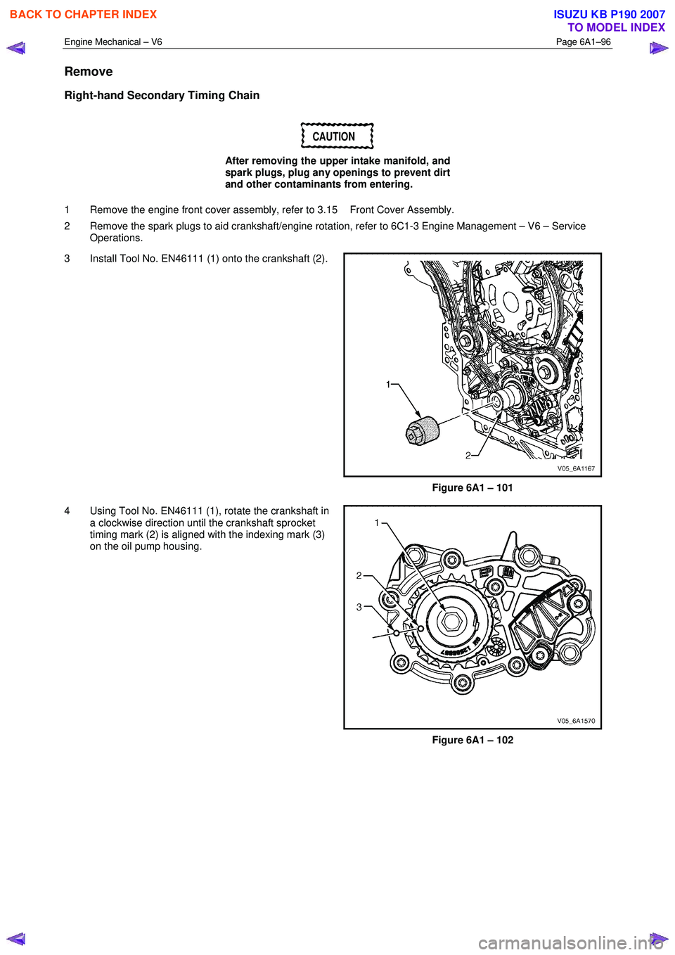
3 Install Tool No. EN46111 (1) onto the crankshaft (2).
Figure 6A1 – 101
4 Using Tool No. EN46111 (1), rotate the crankshaft in a clockwise direction until the crankshaft sprocket
timing mark (2) is aligned with the indexing mark (3)
on the oil pump housing.
Figure 6A1 – 102
BACK TO CHAPTER INDEX
TO MODEL INDEX
ISUZU KB P190 2007
Page 2587 of 6020
Engine Mechanical – V6 Page 6A1–108
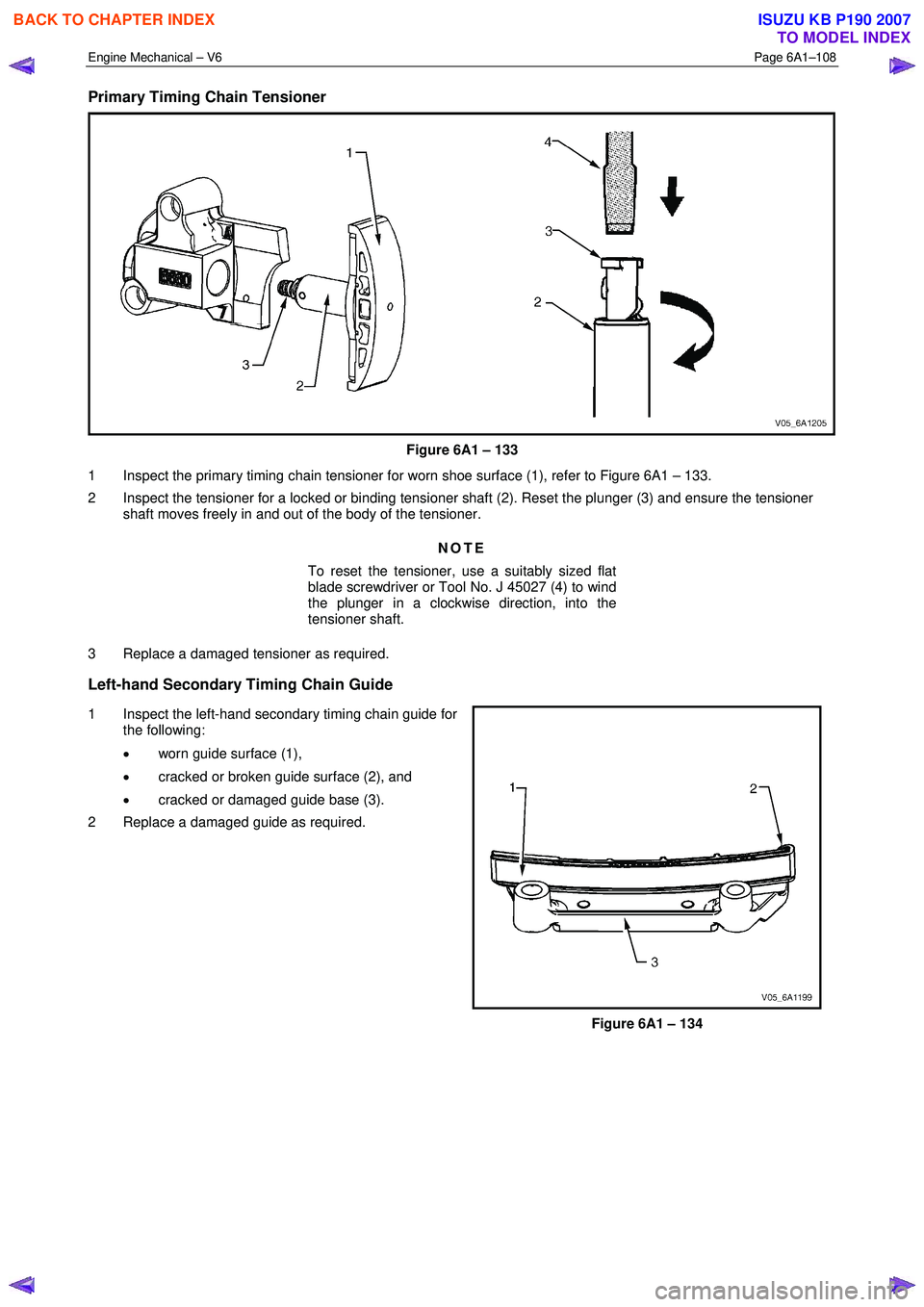
Primary Timing Chain Tensioner
Figure 6A1 – 133
1 Inspect the primary timing chain tensioner for worn shoe surface (1), refer to Figure 6A1 – 133.
2 Inspect the tensioner for a locked or binding tensioner shaft (2). Reset the plunger (3) and ensure the tensioner shaft moves freely in and out of the body of the tensioner.
NOTE
To reset the tensioner, use a suitably sized flat
blade screwdriver or Tool No. J 45027 (4) to wind
the plunger in a clockwise direction, into the
tensioner shaft.
3 Replace a damaged tensioner as required.
Left-hand Secondary Timing Chain Guide
1 Inspect the left-hand secondary timing chain guide for the following:
• worn guide surface (1),
• cracked or broken guide surface (2), and
• cracked or damaged guide base (3).
2 Replace a damaged guide as required.
Figure 6A1 – 134
BACK TO CHAPTER INDEX
TO MODEL INDEX
ISUZU KB P190 2007
Page 2589 of 6020
Engine Mechanical – V6 Page 6A1–110
2 Inspect the tensioner for locked or binding tensioner shaft (2). Reset the plunger (3) and ensure the tensioner shaft
moves freely in and out of the body of the tensioner.
NOTE
To reset the tensioner, use a suitably sized flat
blade screwdriver or Tool No. J 45027 (4) to wind
the plunger in a clockwise direction, into the
tensioner shaft.
3 Replace a damaged tensioner as required.
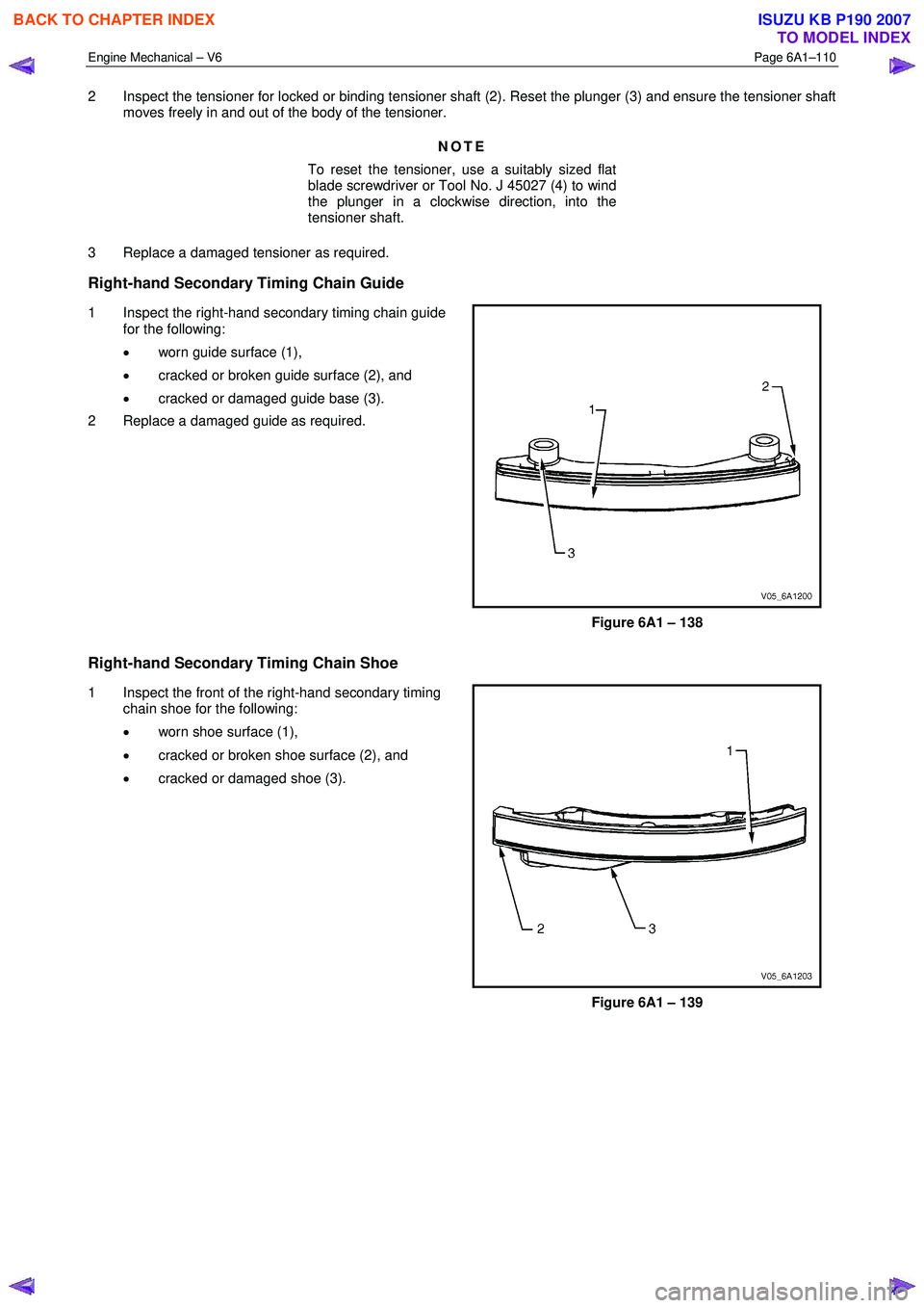
Right-hand Secondary Timing Chain Guide
1 Inspect the right-hand secondary timing chain guide for the following:
• worn guide surface (1),
• cracked or broken guide surface (2), and
• cracked or damaged guide base (3).
2 Replace a damaged guide as required.
Figure 6A1 – 138
Right-hand Secondary Timing Chain Shoe
1 Inspect the front of the right-hand secondary timing chain shoe for the following:
• worn shoe surface (1),
• cracked or broken shoe surface (2), and
• cracked or damaged shoe (3).
Figure 6A1 – 139
BACK TO CHAPTER INDEX
TO MODEL INDEX
ISUZU KB P190 2007
Page 2590 of 6020
Engine Mechanical – V6 Page 6A1–111
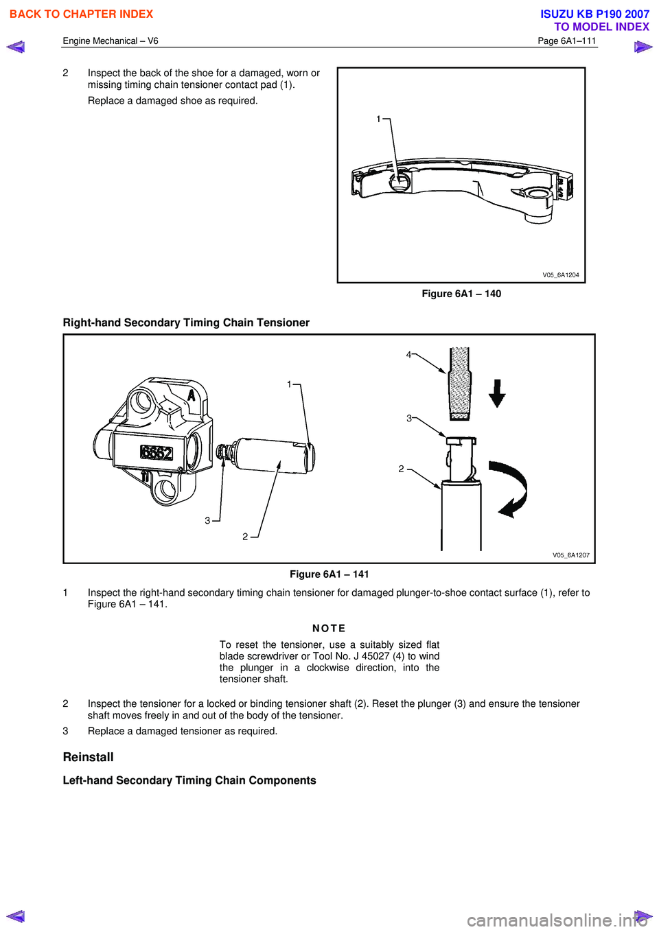
2 Inspect the back of the shoe for a damaged, worn or
missing timing chain tensioner contact pad (1).
Replace a damaged shoe as required.
Figure 6A1 – 140
Right-hand Secondary Timing Chain Tensioner
Figure 6A1 – 141
1 Inspect the right-hand secondary timing chain tensioner for damaged plunger-to-shoe contact surface (1), refer to Figure 6A1 – 141.
NOTE
To reset the tensioner, use a suitably sized flat
blade screwdriver or Tool No. J 45027 (4) to wind
the plunger in a clockwise direction, into the
tensioner shaft.
2 Inspect the tensioner for a locked or binding tensioner shaft (2). Reset the plunger (3) and ensure the tensioner shaft moves freely in and out of the body of the tensioner.
3 Replace a damaged tensioner as required.
Reinstall
Left-hand Secondary Timing Chain Components
BACK TO CHAPTER INDEX
TO MODEL INDEX
ISUZU KB P190 2007
Page 2591 of 6020
Engine Mechanical – V6 Page 6A1–112
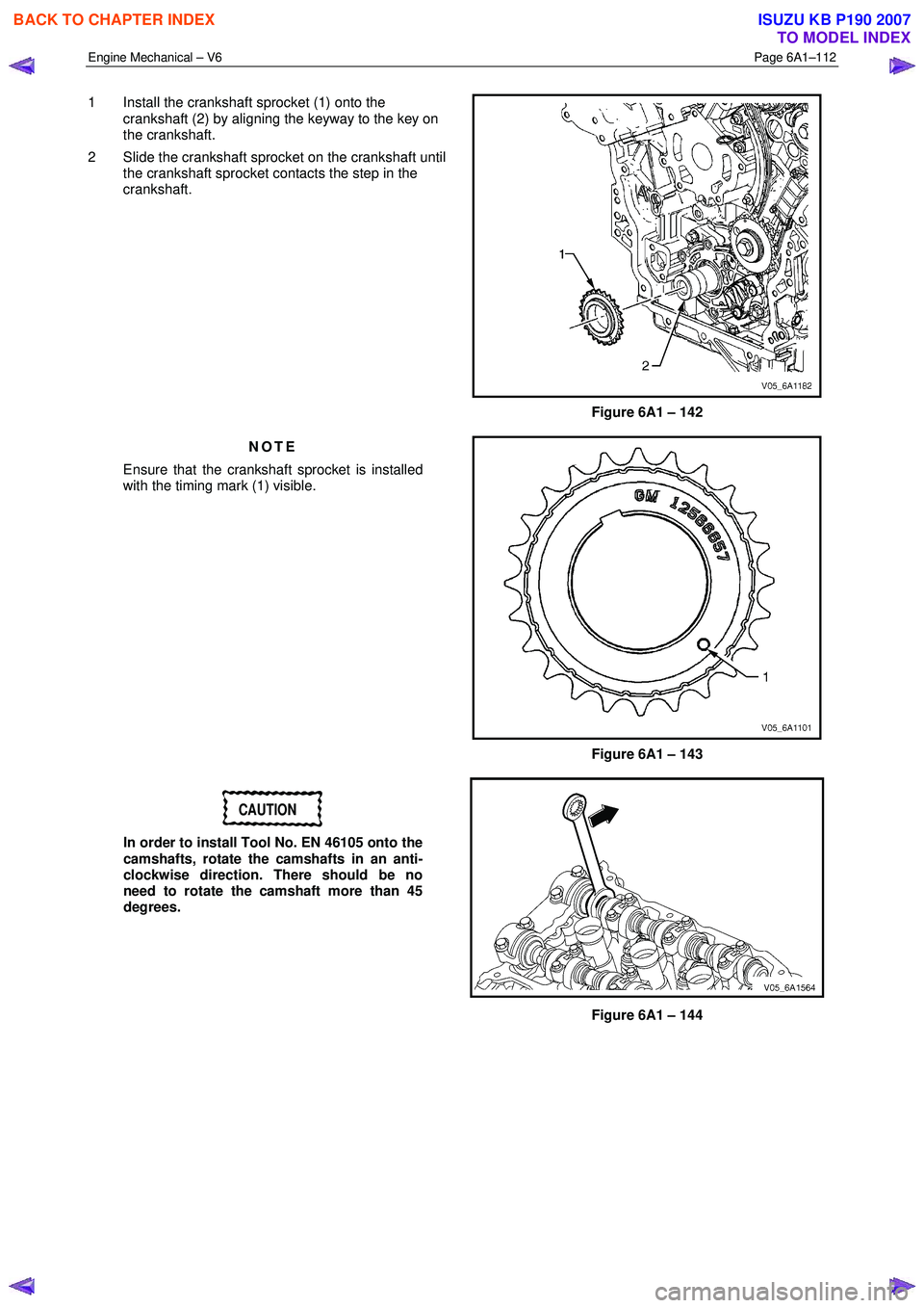
1 Install the crankshaft sprocket (1) onto the
crankshaft (2) by aligning the keyway to the key on
the crankshaft.
2 Slide the crankshaft sprocket on the crankshaft until the crankshaft sprocket contacts the step in the
crankshaft.
Figure 6A1 – 142
NOTE
Ensure that the crankshaft sprocket is installed
with the timing mark (1) visible.
Figure 6A1 – 143
CAUTION
In order to install Tool No. EN 46105 onto the
camshafts, rotate the camshafts in an anti-
clockwise direction. There should be no
need to rotate the camshaft more than 45
degrees.
Figure 6A1 – 144
BACK TO CHAPTER INDEX
TO MODEL INDEX
ISUZU KB P190 2007
Page 2592 of 6020
Engine Mechanical – V6 Page 6A1–113
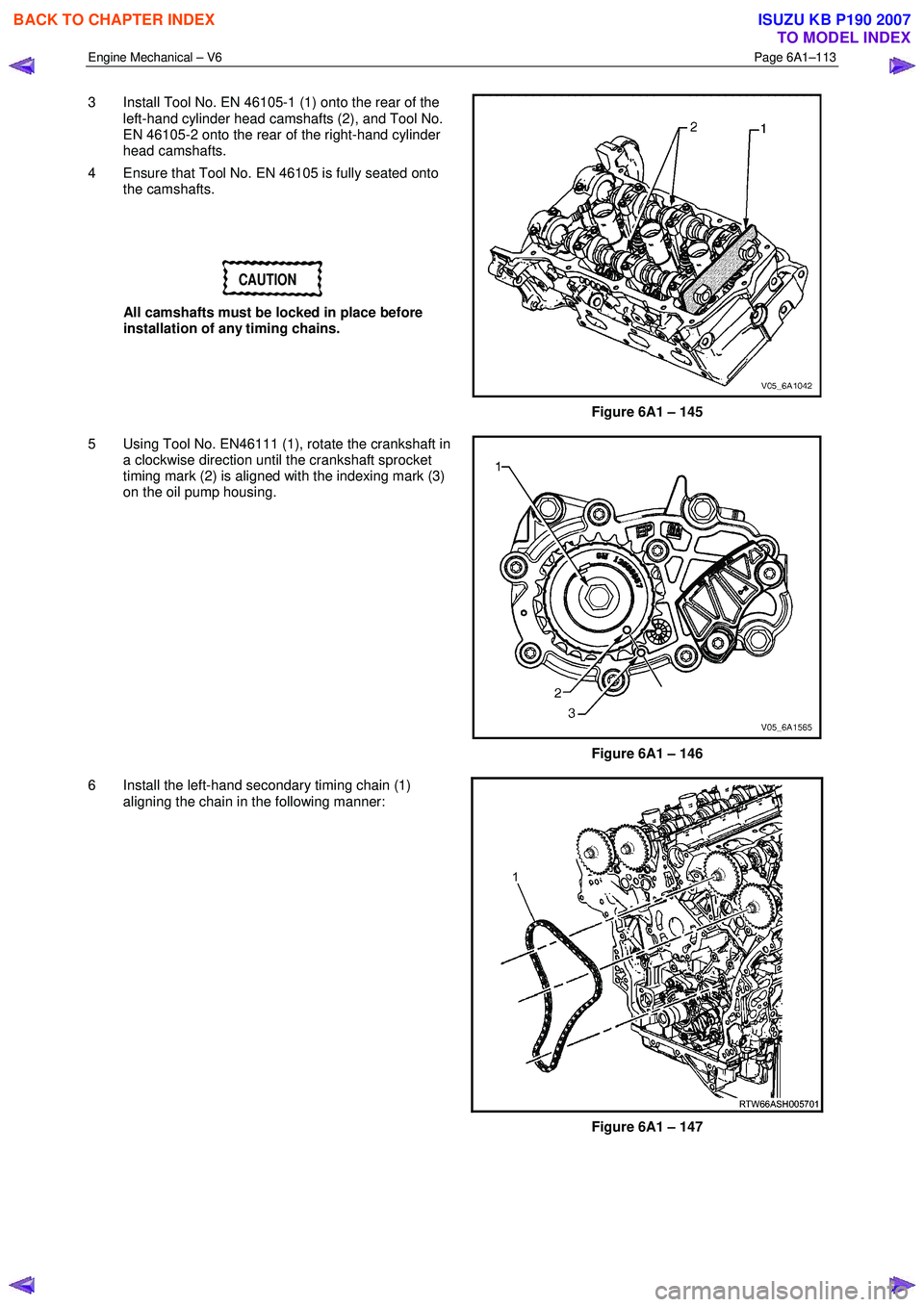
3 Install Tool No. EN 46105-1 (1) onto the rear of the
left-hand cylinder head camshafts (2), and Tool No.
EN 46105-2 onto the rear of the right-hand cylinder
head camshafts.
4 Ensure that Tool No. EN 46105 is fully seated onto the camshafts.
CAUTION
All camshafts must be locked in place before
installation of any timing chains.
Figure 6A1 – 145
5 Using Tool No. EN46111 (1), rotate the crankshaft in a clockwise direction until the crankshaft sprocket
timing mark (2) is aligned with the indexing mark (3)
on the oil pump housing.
Figure 6A1 – 146
6 Install the left-hand secondary timing chain (1) aligning the chain in the following manner:
Figure 6A1 – 147
BACK TO CHAPTER INDEX
TO MODEL INDEX
ISUZU KB P190 2007
Page 2597 of 6020
Engine Mechanical – V6 Page 6A1–118
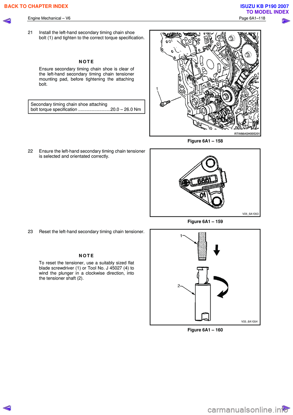
21 Install the left-hand secondary timing chain shoe
bolt (1) and tighten to the correct torque specification.
NOTE
Ensure secondary timing chain shoe is clear of
the left-hand secondary timing chain tensioner
mounting pad, before tightening the attaching
bolt.
Secondary timing chain shoe attaching
bolt torque specification ..........................20.0 – 26.0 Nm
Figure 6A1 – 158
22 Ensure the left-hand secondary timing chain tensioner is selected and orientated correctly.
Figure 6A1 – 159
23 Reset the left-hand secondary timing chain tensioner.
NOTE
To reset the tensioner, use a suitably sized flat
blade screwdriver (1) or Tool No. J 45027 (4) to
wind the plunger in a clockwise direction, into
the tensioner shaft (2).
Figure 6A1 – 160
BACK TO CHAPTER INDEX
TO MODEL INDEX
ISUZU KB P190 2007
Page 2604 of 6020
Engine Mechanical – V6 Page 6A1–125
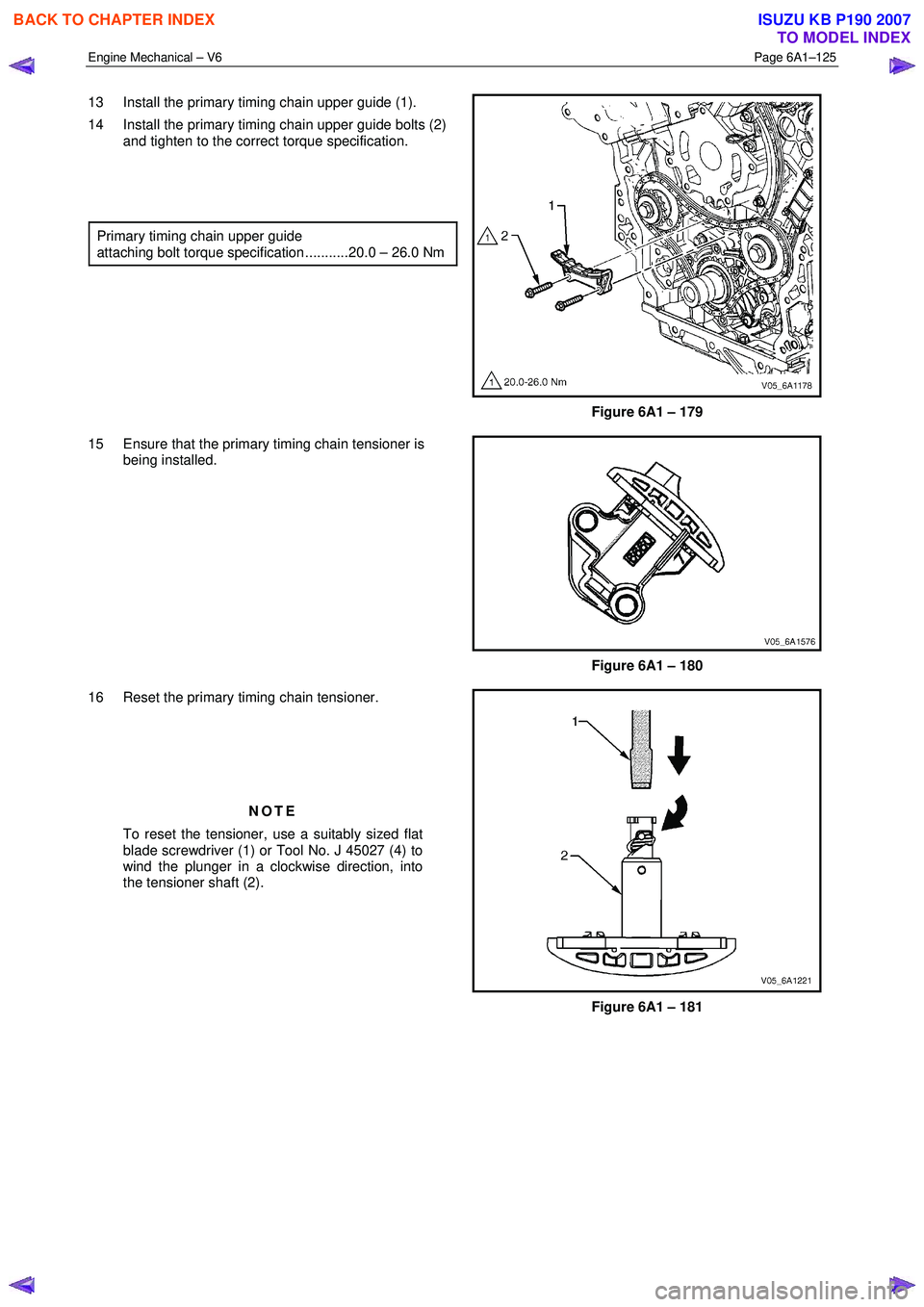
13 Install the primary timing chain upper guide (1).
14 Install the primary timing chain upper guide bolts (2) and tighten to the correct torque specification.
Primary timing chain upper guide
attaching bolt torque specification ...........20.0 – 26.0 Nm
Figure 6A1 – 179
15 Ensure that the primary timing chain tensioner is being installed.
Figure 6A1 – 180
16 Reset the primary timing chain tensioner.
NOTE
To reset the tensioner, use a suitably sized flat
blade screwdriver (1) or Tool No. J 45027 (4) to
wind the plunger in a clockwise direction, into
the tensioner shaft (2).
Figure 6A1 – 181
BACK TO CHAPTER INDEX
TO MODEL INDEX
ISUZU KB P190 2007
Page 2607 of 6020
Engine Mechanical – V6 Page 6A1–128
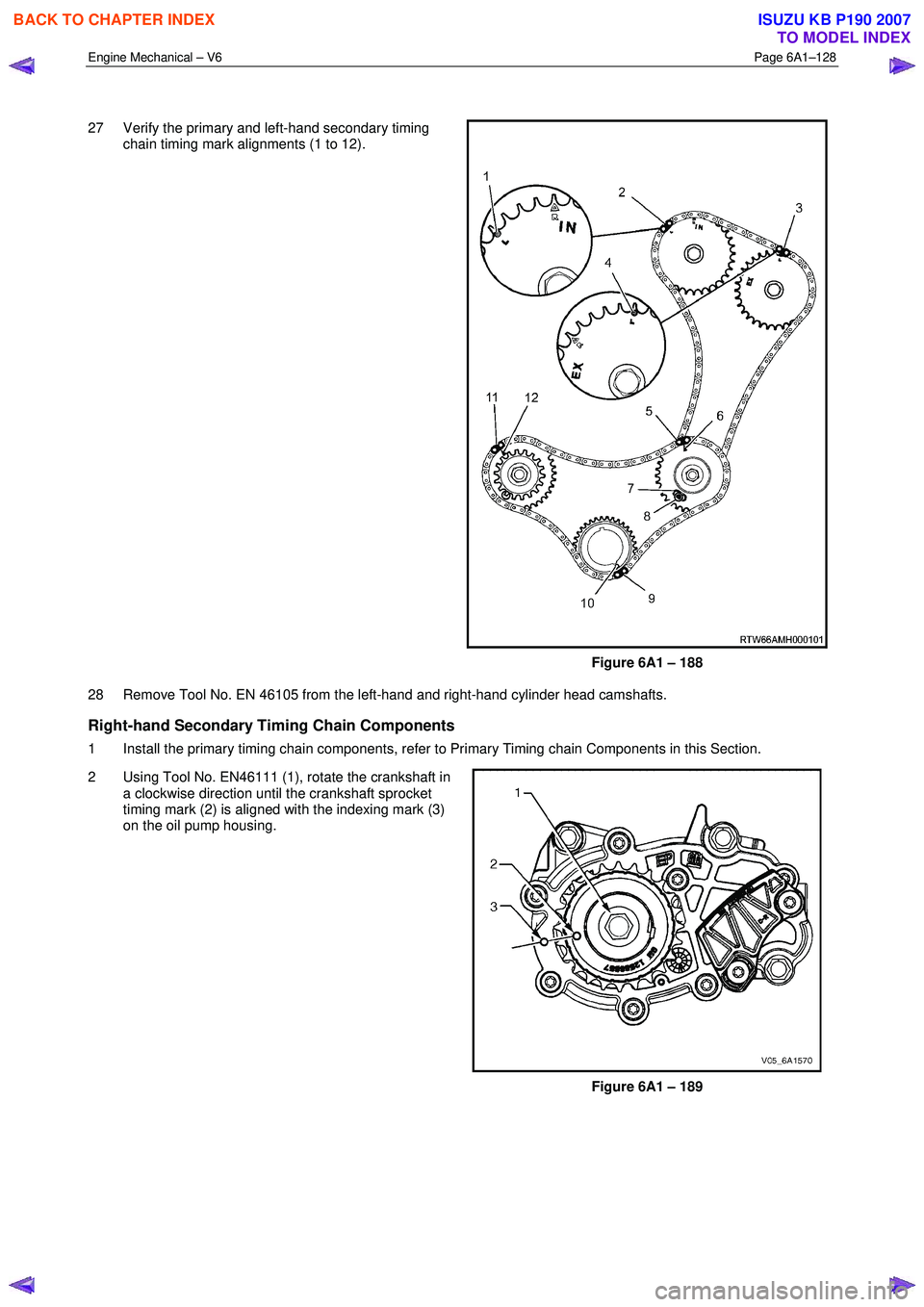
27 Verify the primary and left-hand secondary timing chain timing mark alignments (1 to 12).
Figure 6A1 – 188
28 Remove Tool No. EN 46105 from the left-hand and right-hand cylinder head camshafts.
Right-hand Secondary Timing Chain Components
1 Install the primary timing chain components, refer to Primary Timing chain Components in this Section.
2 Using Tool No. EN46111 (1), rotate the crankshaft in a clockwise direction until the crankshaft sprocket
timing mark (2) is aligned with the indexing mark (3)
on the oil pump housing.
Figure 6A1 – 189
BACK TO CHAPTER INDEX
TO MODEL INDEX
ISUZU KB P190 2007
Page 2612 of 6020
Engine Mechanical – V6 Page 6A1–133
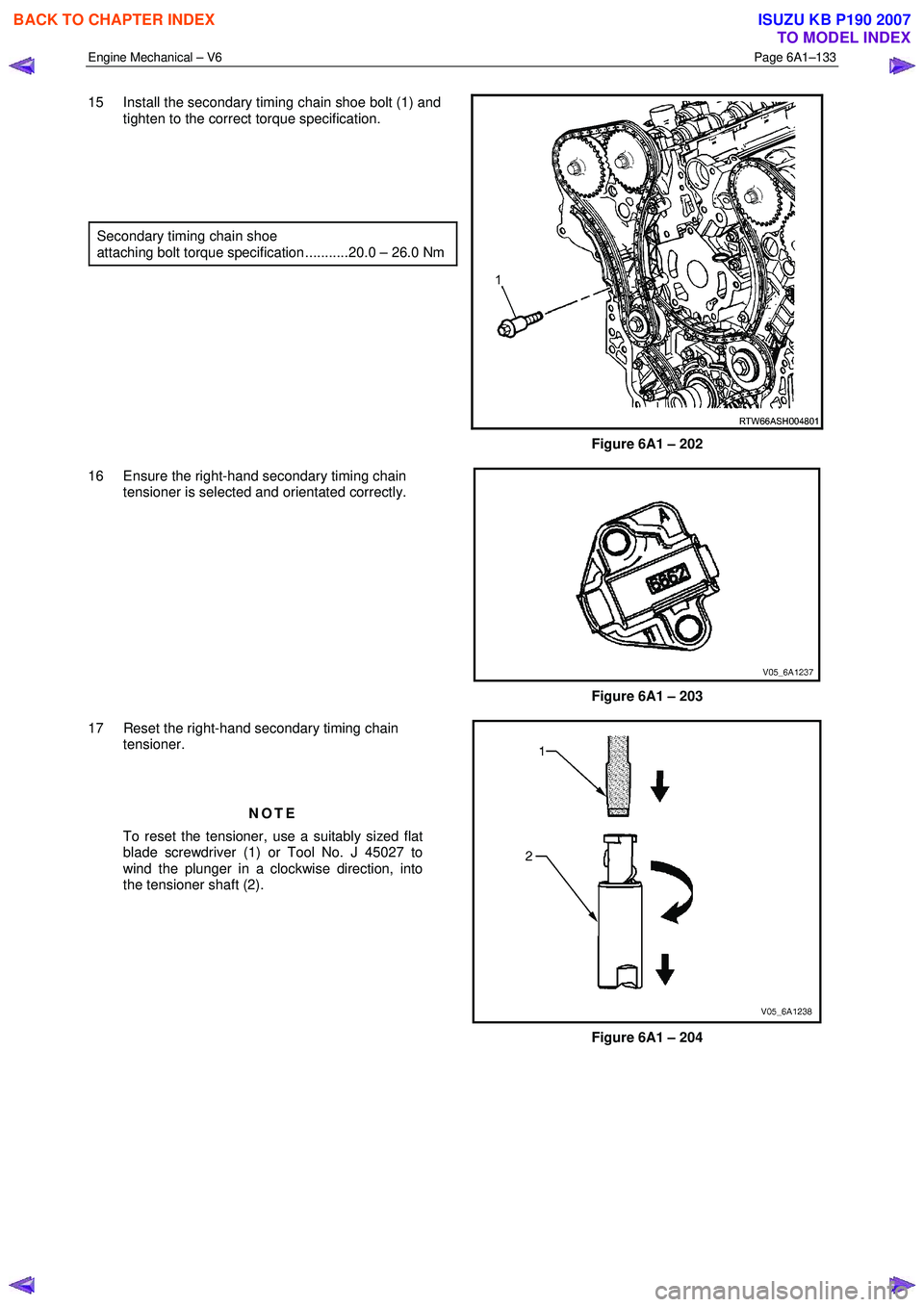
15 Install the secondary timing chain shoe bolt (1) and
tighten to the correct torque specification.
Secondary timing chain shoe
attaching bolt torque specification ...........20.0 – 26.0 Nm
Figure 6A1 – 202
16 Ensure the right-hand secondary timing chain tensioner is selected and orientated correctly.
Figure 6A1 – 203
17 Reset the right-hand secondary timing chain tensioner.
NOTE
To reset the tensioner, use a suitably sized flat
blade screwdriver (1) or Tool No. J 45027 to
wind the plunger in a clockwise direction, into
the tensioner shaft (2).
Figure 6A1 – 204
BACK TO CHAPTER INDEX
TO MODEL INDEX
ISUZU KB P190 2007