clock ISUZU KB P190 2007 Workshop User Guide
[x] Cancel search | Manufacturer: ISUZU, Model Year: 2007, Model line: KB P190, Model: ISUZU KB P190 2007Pages: 6020, PDF Size: 70.23 MB
Page 535 of 6020
FRONT WHEEL DRIVE 4C1-31
Tighten the nut to the specified torque.
N⋅m (kgf ⋅m/lb ⋅in)
New bearing 2.3 (0.23/20)
Used bearing 0.98 - 1.18
(0.10 – 0.12/9 – 10)
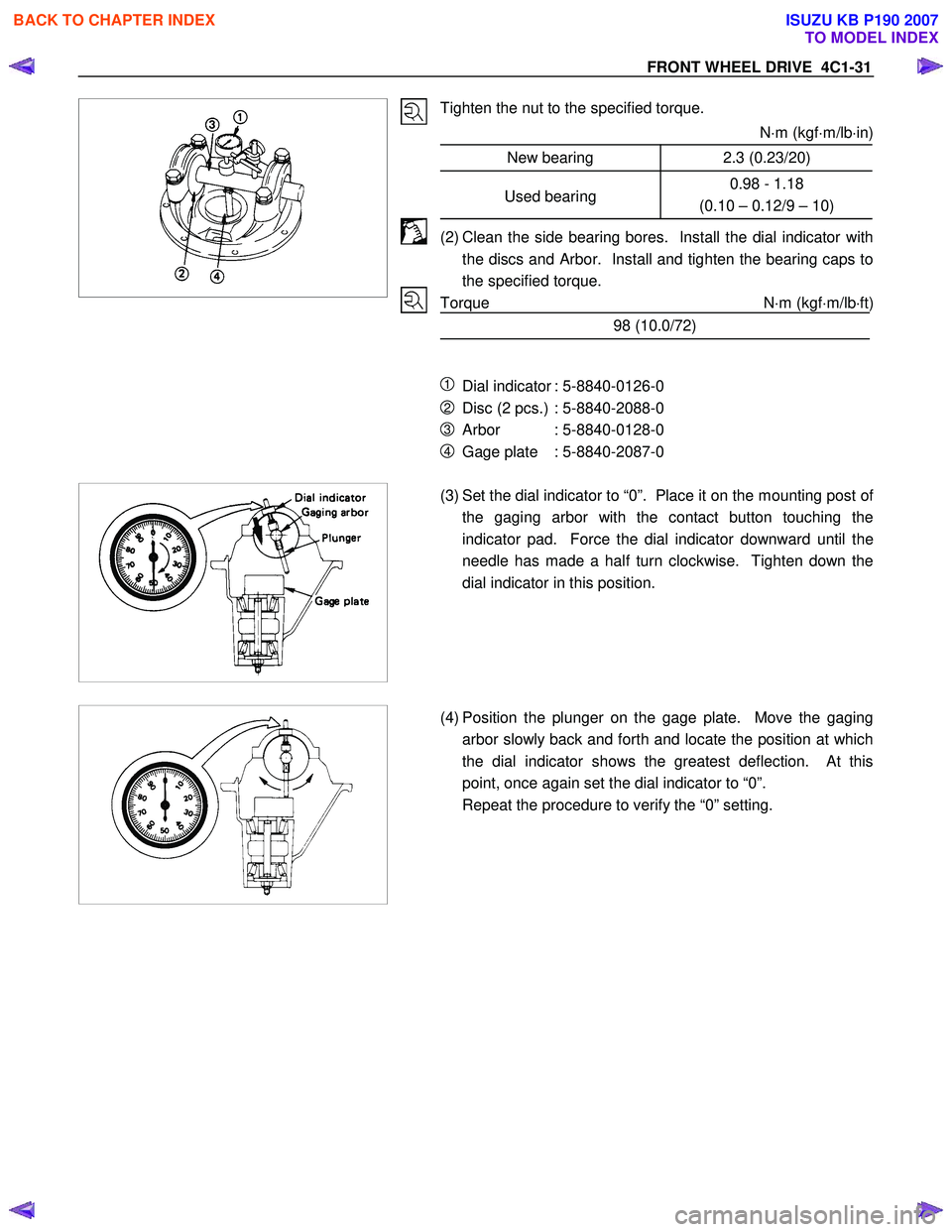
(2) Clean the side bearing bores. Install the dial indicator with the discs and Arbor. Install and tighten the bearing caps to
the specified torque.
Torque N ⋅m (kgf ⋅m/lb ⋅ft)
98 (10.0/72)
1 Dial indicator : 5-8840-0126-0
2 Disc (2 pcs.) : 5-8840-2088-0
3 Arbor : 5-8840-0128-0
4 Gage plate : 5-8840-2087-0
(3) Set the dial indicator to “0”. Place it on the mounting post of
the gaging arbor with the contact button touching the
indicator pad. Force the dial indicator downward until the
needle has made a half turn clockwise. Tighten down the
dial indicator in this position.
(4) Position the plunger on the gage plate. Move the gaging
arbor slowly back and forth and locate the position at which
the dial indicator shows the greatest deflection. At this
point, once again set the dial indicator to “0”.
Repeat the procedure to verify the “0” setting.
BACK TO CHAPTER INDEX
TO MODEL INDEX
ISUZU KB P190 2007
Page 558 of 6020
4C1-54 FRONT WHEEL DRIVE
Important Operations
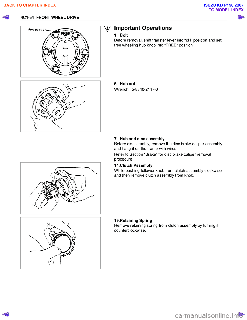
1. Bolt
Before removal, shift transfer lever into “2H” position and set
free wheeling hub knob into “FREE” position.
6. Hub nut
W rench : 5-8840-2 117-0
7. Hub and disc assembly
Before disassembly, remove the disc brake caliper assembly
and hang it on the frame with wires.
Refer to Section “Brake” for disc brake caliper removal
procedure.
14. Clutch Assembly
W hile pushing follower knob, turn clutch assembly clockwise
and then remove clutch assembly from knob.
19. Retaining Spring
Remove retaining spring from clutch assembly by turning it
counterclockwise.
BACK TO CHAPTER INDEX
TO MODEL INDEX
ISUZU KB P190 2007
Page 562 of 6020
4C1-58 FRONT WHEEL DRIVE
Important Operations
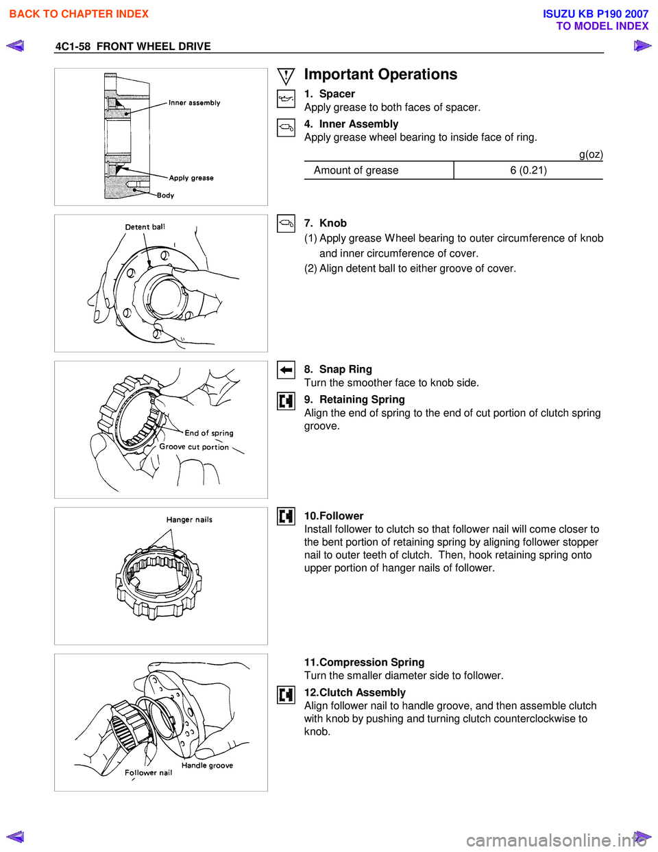
1. Spacer
Apply grease to both faces of spacer.
4. Inner Assembly
Apply grease wheel bearing to inside face of ring.
g(oz)
Amount of grease 6 (0.21)
7. Knob
( 1 ) Apply grease W heel bearing to outer circumference of knob
and inner circumference of cover.
(2) Align detent ball to either groove of cover.
8. Snap Ring
Turn the smoother face to knob side.
9. Retaining Spring
Align the end of spring to the end of cut portion of clutch spring
groove.
10. Follower
Install follower to clutch so that follower nail will come closer to
the bent portion of retaining spring by aligning follower stopper
nail to outer teeth of clutch. Then, hook retaining spring onto
upper portion of hanger nails of follower.
11. Compression Spring
Turn the smaller diameter side to follower.
12. Clutch Assembly
Align follower nail to handle groove, and then assemble clutch
with knob by pushing and turning clutch counterclockwise to
knob.
BACK TO CHAPTER INDEX
TO MODEL INDEX
ISUZU KB P190 2007
Page 723 of 6020
5C-24 BRAKES
RTW 35CSH000201
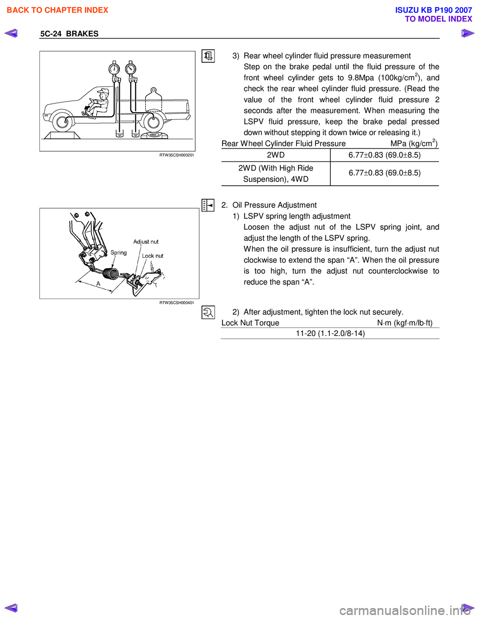
3) Rear wheel cylinder fluid pressure measurement
Step on the brake pedal until the fluid pressure of the front wheel cylinder gets to 9.8Mpa (100kg/cm
2), and
check the rear wheel cylinder fluid pressure. (Read the
value of the front wheel cylinder fluid pressure 2
seconds after the measurement. W hen measuring the
LSPV fluid pressure, keep the brake pedal pressed
down without stepping it down twice or releasing it.)
Rear W heel Cylinder Fluid Pressure MPa (kg/cm
2)
2W D 6.77 ±0.83 (69.0 ±8.5)
2W D (W ith High Ride
Suspension), 4W D 6.77
±0.83 (69.0 ±8.5)
RTW 35CSH000401
2. Oil Pressure Adjustment
1) LSPV spring length adjustment
Loosen the adjust nut of the LSPV spring joint, and adjust the length of the LSPV spring.
W hen the oil pressure is insufficient, turn the adjust nut clockwise to extend the span “A”. W hen the oil pressure
is too high, turn the adjust nut counterclockwise to
reduce the span “A”.
2) After adjustment, tighten the lock nut securely.
Lock Nut Torque N⋅m (kgf ⋅m/lb ⋅ft)
11-20 (1.1-2.0/8-14)
BACK TO CHAPTER INDEX
TO MODEL INDEX
ISUZU KB P190 2007
Page 730 of 6020
BRAKES 5C-31
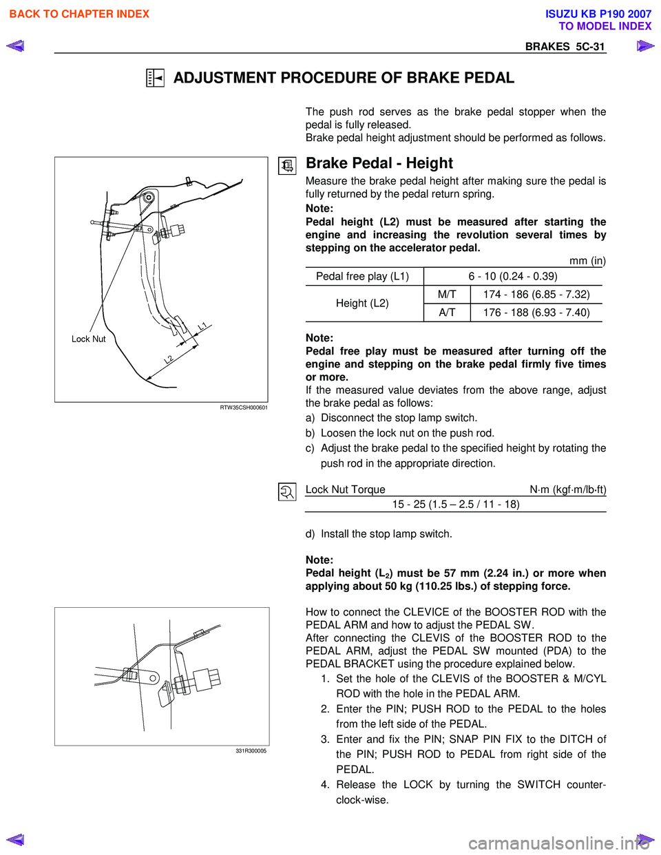
ADJUSTMENT PROCEDURE OF BRAKE PEDAL
The push rod serves as the brake pedal stopper when the
pedal is fully released.
Brake pedal height adjustment should be performed as follows.
RTW 35CSH000601
Brake Pedal - Height
Measure the brake pedal height after making sure the pedal is
fully returned by the pedal return spring.
Note:
Pedal height (L2) must be measured after starting the
engine and increasing the revolution several times by
stepping on the accelerator pedal. mm (in)
Pedal free play (L1) 6 - 10 (0.24 - 0.39)
M/T 174 - 186 (6.85 - 7.32) Height (L2)
A/T 176 - 188 (6.93 - 7.40)
Note:
Pedal free play must be measured after turning off the
engine and stepping on the brake pedal firmly five times
or more.
If the measured value deviates from the above range, adjust
the brake pedal as follows:
a) Disconnect the stop lamp switch.
b) Loosen the lock nut on the push rod.
c)
Adjust the brake pedal to the specified height by rotating the
push rod in the appropriate direction.
Lock Nut Torque
N⋅m (kgf ⋅m/lb ⋅
⋅⋅
⋅
ft)
15 - 25 (1.5 – 2.5 / 11 - 18)
d) Install the stop lamp switch.
Note:
Pedal height (L
2) must be 57 mm (2.24 in.) or more when
applying about 50 kg (110.25 lbs.) of stepping force.
331R300005
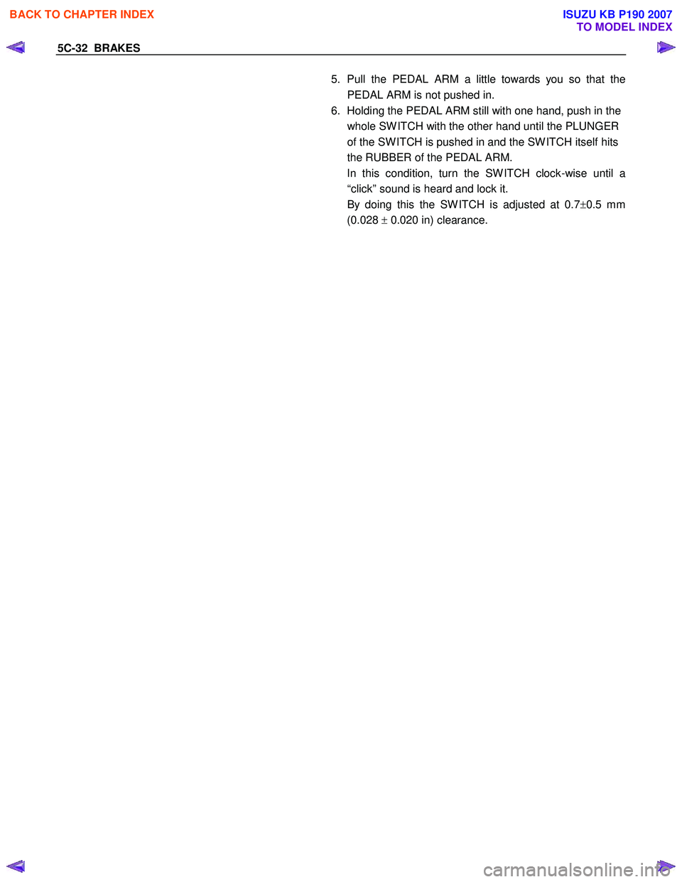
How to connect the CLEVICE of the BOOSTER ROD with the
PEDAL ARM and how to adjust the PEDAL SW .
After connecting the CLEVIS of the BOOSTER ROD to the
PEDAL ARM, adjust the PEDAL SW mounted (PDA) to the
PEDAL BRACKET using the procedure explained below.
1. Set the hole of the CLEVIS of the BOOSTER & M/CYL
ROD with the hole in the PEDAL ARM.
2. Enter the PIN; PUSH ROD to the PEDAL to the holes from the left side of the PEDAL.
3. Enter and fix the PIN; SNAP PIN FIX to the DITCH o
f
the PIN; PUSH ROD to PEDAL from right side of the
PEDAL.
4. Release the LOCK by turning the SW ITCH counter- clock-wise.
BACK TO CHAPTER INDEX
TO MODEL INDEX
ISUZU KB P190 2007
Page 731 of 6020
5C-32 BRAKES
5. Pull the PEDAL ARM a little towards you so that the
PEDAL ARM is not pushed in.
6. Holding the PEDAL ARM still with one hand, push in the whole SW ITCH with the other hand until the PLUNGER
of the SW ITCH is pushed in and the SW ITCH itself hits
the RUBBER of the PEDAL ARM.
In this condition, turn the SW ITCH clock-wise until a “click” sound is heard and lock it.
By doing this the SW ITCH is adjusted at 0.7 ±0.5 mm
(0.028 ± 0.020 in) clearance.
BACK TO CHAPTER INDEX
TO MODEL INDEX
ISUZU KB P190 2007
Page 829 of 6020
6A – 24 ENGINE MECHANICAL
SERVICING
Servicing refers to general maintenance procedures to be performed by qualified service personnel.
RTW 36ASH000401
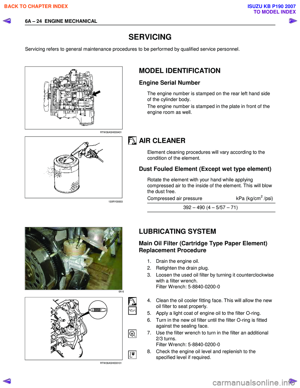
MODEL IDENTIFICATION
Engine Serial Number
The engine number is stamped on the rear left hand side
of the cylinder body.
The engine number is stamped in the plate in front of the
engine room as well.
AIR CLEANER
Element cleaning procedures will vary according to the
condition of the element.
Dust Fouled Element (Except wet type element)
Rotate the element with your hand while applying
compressed air to the inside of the element. This will blow
the dust free.
Compressed air pressure kPa (kg/cm
2 /psi)
392 – 490 (4 – 5/57 – 71)
LUBRICATING SYSTEM
Main Oil Filter (Cartridge Type Paper Element)
Replacement Procedure
1. Drain the engine oil.
2. Retighten the drain plug.
3. Loosen the used oil filter by turning it counterclockwise with a filter wrench.
Filter W rench: 5-8840-0200-0
RTW 36ASH000101
4. Clean the oil cooler fitting face. This will allow the new oil filter to seat properly.
5. Apply a light coat of engine oil to the filter O-ring.
6. Turn in the new oil filter until the filter O-ring is fitted against the sealing face.
7. Use the filter wrench to turn in the filter an additional 2/3 turns.
Filter W rench: 5-8840-0200-0
8. Check the engine oil level and replenish to the specified level if required.
130RY00003
6A-6
BACK TO CHAPTER INDEX
TO MODEL INDEX
ISUZU KB P190 2007
Page 830 of 6020
ENGINE MECHANICAL 6A – 25
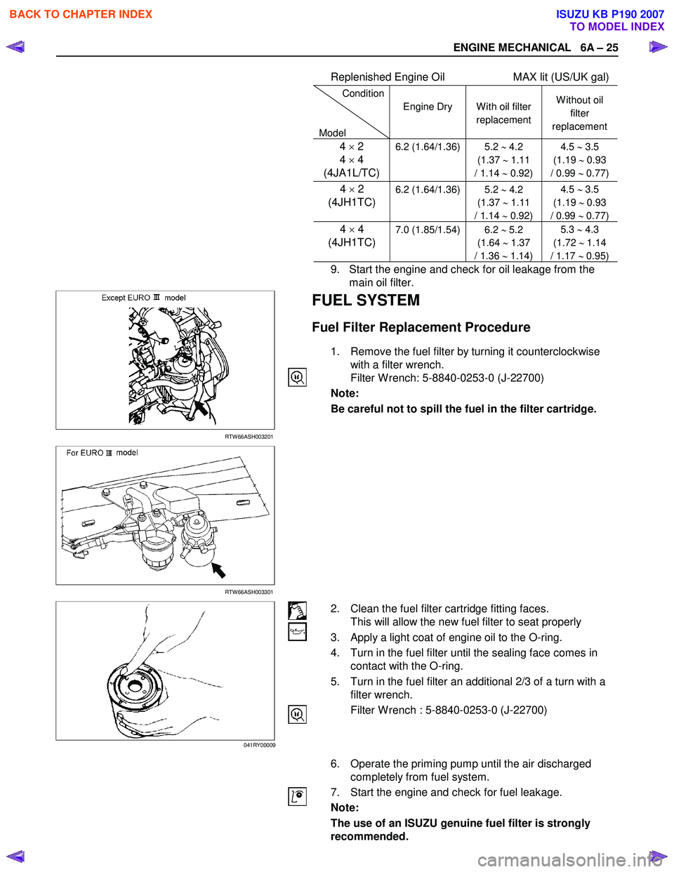
Replenished Engine Oil MAX lit (US/UK gal)
Condition
Model Engine Dry
W ith oil filter
replacement W ithout oil
filter
replacement
4 × 2
4 × 4
(4JA1L/TC)6.2 (1.64/1.36) 5.2 ∼ 4.2
(1.37 ∼ 1.11
/ 1.14 ∼ 0.92) 4.5
∼ 3.5
(1.19 ∼ 0.93
/ 0.99 ∼ 0.77)
4 × 2
(4JH1TC)
6.2 (1.64/1.36) 5.2
∼ 4.2
(1.37 ∼ 1.11
/ 1.14 ∼ 0.92) 4.5
∼ 3.5
(1.19 ∼ 0.93
/ 0.99 ∼ 0.77)
4 × 4
(4JH1TC) 7.0 (1.85/1.54) 6.2 ∼ 5.2
(1.64 ∼ 1.37
/ 1.36 ∼ 1.14) 5.3
∼ 4.3
(1.72 ∼ 1.14
/ 1.17 ∼ 0.95)
9. Start the engine and check for oil leakage from the
main oil filter.
RTW 66ASH003201
FUEL SYSTEM
Fuel Filter Replacement Procedure
1. Remove the fuel filter by turning it counterclockwise with a filter wrench.
Filter W rench: 5-8840-0253-0 (J-22700)
Note:
Be careful not to spill the fuel in the filter cartridge.
RTW 66ASH003301
2. Clean the fuel filter cartridge fitting faces. This will allow the new fuel filter to seat properly
3. Apply a light coat of engine oil to the O-ring.
4. Turn in the fuel filter until the sealing face comes in contact with the O-ring.
5. Turn in the fuel filter an additional 2/3 of a turn with a filter wrench.
Filter W rench : 5-8840-0253-0 (J-22700)
6. Operate the priming pump until the air discharged completely from fuel system.
7. Start the engine and check for fuel leakage.
Note:
The use of an ISUZU genuine fuel filter is strongly
recommended.
041RY00009
BACK TO CHAPTER INDEX
TO MODEL INDEX
ISUZU KB P190 2007
Page 839 of 6020
6A – 34 ENGINE MECHANICAL
RTW 46ASH000701
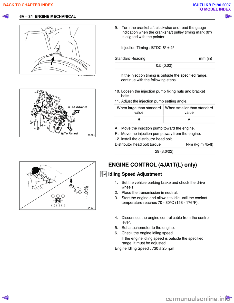
9. Turn the crankshaft clockwise and read the gauge
indication when the crankshaft pulley timing mark (8 °)
is aligned with the pointer.
Injection Timing : BTDC 8 ° ± 2 °
Standard Reading mm (in)
0.5 (0.02)
If the injection timing is outside the specified range,
continue with the following steps.
10. Loosen the injection pump fixing nuts and bracket bolts.
11. Adjust the injection pump setting angle.
W hen large than standard value W hen smaller than standard
value
R A
A: Move the injection pump toward the engine.
R: Move the injection pump away from the engine.
12. Install the distributor head bolt.
Distributor head bolt torque N·m (kg·m /lb·ft)
29 (3.0/22)
ENGINE CONTROL (4JA1T(L) only)
Idling Speed Adjustment
1. Set the vehicle parking brake and chock the drive wheels.
2. Place the transmission in neutral.
3. Start the engine and allow it to idle until the coolant temperature reaches 70 - 80 °C (158 - 176 °F).
4. Disconnect the engine control cable from the control lever.
5. Set a tachometer to the engine.
6. Check the engine idling speed. If the engine idling speed is outside the specified
range, it must be adjusted.
Engine Idling Speed : 730 ± 25 rpm
BACK TO CHAPTER INDEX
TO MODEL INDEX
ISUZU KB P190 2007
Page 915 of 6020
6A – 110 ENGINE MECHANICAL
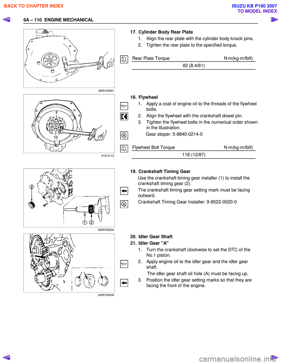
17. Cylinder Body Rear Plate
1. Align the rear plate with the cylinder body knock pins.
2. Tighten the rear plate to the specified torque.
Rear Plate Torque N·m(kg·m/lbft)
82 (8.4/61)
18. Flywheel
1. Apply a coat of engine oil to the threads of the flywheel bolts.
2. Align the flywheel with the crankshaft dowel pin.
3. Tighten the flywheel bolts in the numerical order shown in the illustration.
Gear stoper: 5-8840-0214-0
Flywheel Bolt Torque N·m(kg·m/lbft)
118 (12/87)
19. Crankshaft Timing Gear
Use the crankshaft timing gear installer (1) to install the
crankshaft timing gear (2).
The crankshaft timing gear setting mark must be facing
outward.
Crankshaft Timing Gear Installer: 9-8522-0020-0
20. Idler Gear Shaft
21. Idler Gear "A"
1. Turn the crankshaft clockwise to set the DTC of the No.1 piston.
2. Apply engine oil to the idler gear and the idler gear shaft.
The idler gear shaft oil hole (A) must be facing up.
3. Position the idler gear setting marks so that they are facing the front of the engine.
015LX113
020R100001
020RY00034
020RY00035
BACK TO CHAPTER INDEX
TO MODEL INDEX
ISUZU KB P190 2007