relay ISUZU KB P190 2007 Workshop Owner's Guide
[x] Cancel search | Manufacturer: ISUZU, Model Year: 2007, Model line: KB P190, Model: ISUZU KB P190 2007Pages: 6020, PDF Size: 70.23 MB
Page 1056 of 6020
6E-22 Engine Control System (4JH1)
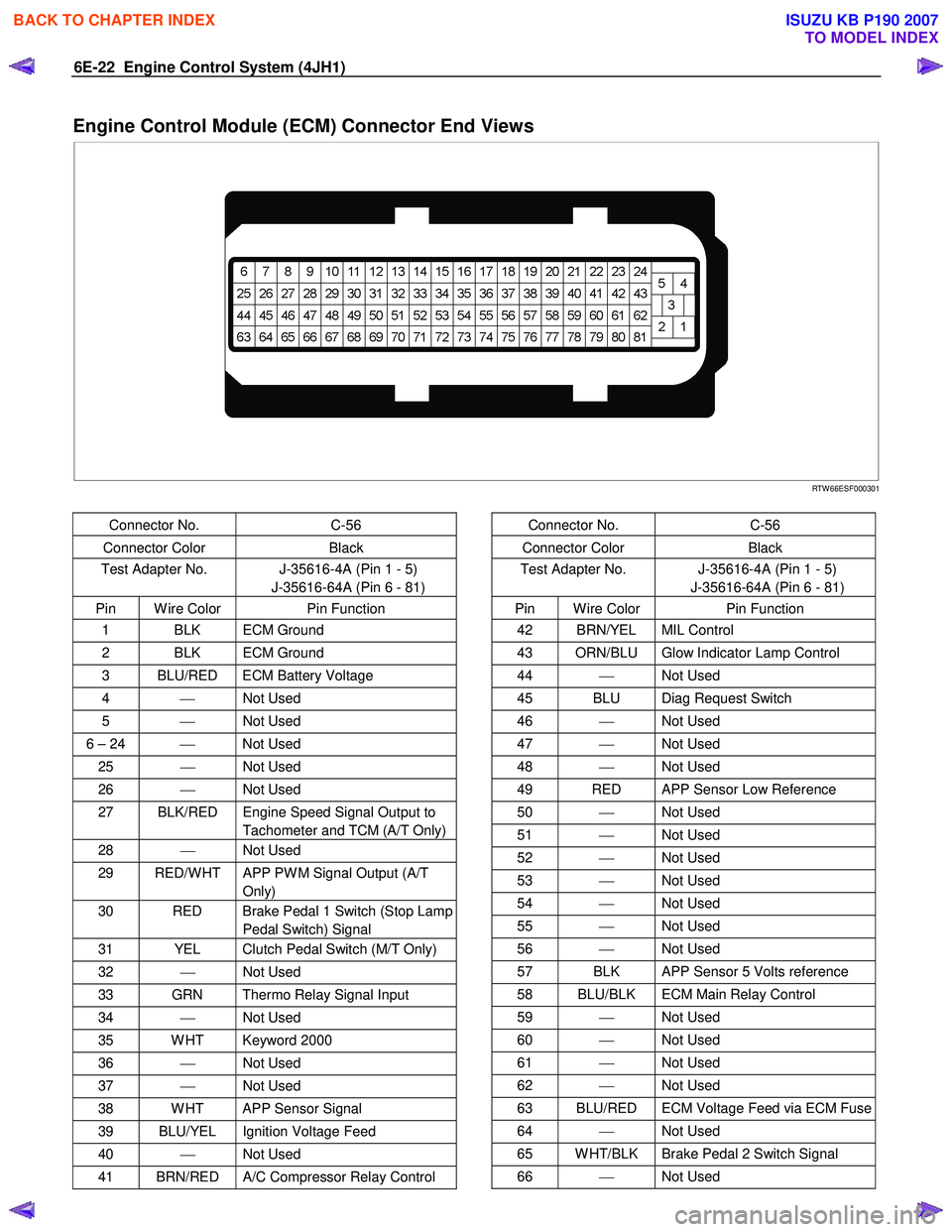
Engine Control Module (ECM) Connector End Views
RTW 66ESF000301
Connector No. C-56
Connector Color Black
Test Adapter No. J-35616-4A (Pin 1 - 5)
J-35616-64A (Pin 6 - 81)
Pin W ire Color Pin Function
1 BLK ECM Ground
2 BLK ECM Ground
3 BLU/RED ECM Battery Voltage
4 Not Used
5 Not Used
6 – 24 Not Used
25 Not Used
26 Not Used
27 BLK/RED Engine Speed Signal Output to
Tachometer and TCM (A/T Only)
28 Not Used
29 RED/W HT APP PW M Signal Output (A/T
Only)
30 RED Brake Pedal 1 Switch (Stop Lamp Pedal Switch) Signal
31 YEL Clutch Pedal Switch (M/T Only)
32 Not Used
33 GRN Thermo Relay Signal Input
34 Not Used
35 W HT Keyword 2000
36 Not Used
37 Not Used
38 W HT APP Sensor Signal
39 BLU/YEL Ignition Voltage Feed
40 Not Used
41 BRN/RED A/C Compressor Relay Control
Connector No. C-56
Connector Color Black
Test Adapter No. J-35616-4A (Pin 1 - 5)
J-35616-64A (Pin 6 - 81)
Pin W ire Color Pin Function
42 BRN/YEL MIL Control
43 ORN/BLU Glow Indicator Lamp Control
44 Not Used
45 BLU Diag Request Switch
46 Not Used
47 Not Used
48 Not Used
49 RED APP Sensor Low Reference
50 Not Used
51 Not Used
52 Not Used
53 Not Used
54 Not Used
55 Not Used
56 Not Used
57 BLK APP Sensor 5 Volts reference
58 BLU/BLK ECM Main Relay Control
59 Not Used
60 Not Used
61 Not Used
62 Not Used
63 BLU/RED ECM Voltage Feed via ECM Fuse
64 Not Used
65 W HT/BLK Brake Pedal 2 Switch Signal
66 Not Used
BACK TO CHAPTER INDEX
TO MODEL INDEX
ISUZU KB P190 2007
Page 1058 of 6020
6E-24 Engine Control System (4JH1)
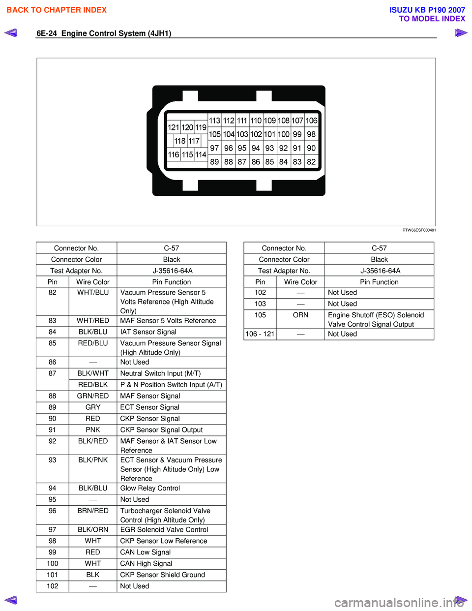
RTW 66ESF000401
Connector No. C-57
Connector Color Black
Test Adapter No. J-35616-64A
Pin W ire Color Pin Function
82 W HT/BLU Vacuum Pressure Sensor 5
Volts Reference (High Altitude
Only)
83 W HT/RED MAF Sensor 5 Volts Reference
84 BLK/BLU IAT Sensor Signal
85 RED/BLU Vacuum Pressure Sensor Signal (High Altitude Only)
86 Not Used
BLK/W HT Neutral Switch Input (M/T) 87
RED/BLK P & N Position Switch Input (A/T)
88 GRN/RED MAF Sensor Signal
89 GRY ECT Sensor Signal
90 RED CKP Sensor Signal
91 PNK CKP Sensor Signal Output
92 BLK/RED MAF Sensor & IAT Sensor Low Reference
93 BLK/PNK ECT Sensor & Vacuum Pressure Sensor (High Altitude Only) Low
Reference
94 BLK/BLU Glow Relay Control
95 Not Used
96 BRN/RED Turbocharger Solenoid Valve
Control (High Altitude Only)
97 BLK/ORN EGR Solenoid Valve Control
98 W HT CKP Sensor Low Reference
99 RED CAN Low Signal
100 W HT CAN High Signal
101 BLK CKP Sensor Shield Ground
102 Not Used
Connector No. C-57
Connector Color Black
Test Adapter No. J-35616-64A
Pin W ire Color Pin Function
102 Not Used
103 Not Used
105 ORN Engine Shutoff (ESO) Solenoid
Valve Control Signal Output
106 - 121 Not Used
BACK TO CHAPTER INDEX
TO MODEL INDEX
ISUZU KB P190 2007
Page 1067 of 6020
Engine Control System (4JH1) 6E-33
Diagnostic System Check - Engine
Controls
Description
The Diagnostic System Check-Engine Controls is an
organized approach to identifying a condition that is
created by a malfunction in the electronic engine control
system. The Diagnostic System Check must be the
starting point for any driveability concern. The
Diagnostic System Check directs the service technician
to the next logical step in order to diagnose the concern.
Understanding and correctly using the diagnostic table
reduces diagnostic time, and prevents the replacement
of good parts.
Test Description
The numbers below refer to the step numbers on the
diagnostic table.
2. Lack of communication may be because of a partial
or a total malfunction of the Keyword 2000 serial data
circuit. The specified procedure determines the
particular condition.
11. If there are other modules with DTCs set, refer to
the DTC list. The DTC list directs you to the appropriate
diagnostic procedure. If the control module stores
multiple DTCs, diagnose the DTCs in the following
order.
• Component level DTCs, such as sensor DTCs,
solenoid DTCs, actuator DTCs, and relay DTCs.
Diagnose the multiple DTCs within this category in
numerical order. Begin with the lowest numbered
DTC, unless the diagnostic table directs you
otherwise.
Important:
• DO NOT perform this diagnostic if there is not a
driveability concern, unless another procedure
directs you to this diagnostic.
• Before you proceed with diagnosis, search fo
r
applicable service bulletins.
• Unless a diagnostic procedure instructs you, DO
NOT clear the DTCs.
• If there is a condition with the starting system, refe
r
to the starting system section in the engine
mechanical.
• Ensure the battery has a full charge.
• Ensure the battery cables (+) (-) are clean and
tight.
• Ensure the ECM grounds are clean, tight, and in
the correct location.
• Ensure the ECM harness connectors are clean and
correctly connected.
• Ensure the ECM terminals are clean and correctl
y
mating.
• Ensure the fuel injection pump control unit (PCU)
ground is clean, tight, and in the correct location.
• Ensure the PCU harness connectors are clean and
correctly connected.
• Ensure the PCU terminals are clean and correctl
y
mating.
• Ensure the vehicle maintenance has been done
enough.
Step Action Value(s) Yes No
1 Install the scan tool.
Does the scan tool turn ON?
Go to Step 2 Go to scan tool
Does Not Power Up
BACK TO CHAPTER INDEX
TO MODEL INDEX
ISUZU KB P190 2007
Page 1070 of 6020
6E-36 Engine Control System (4JH1)
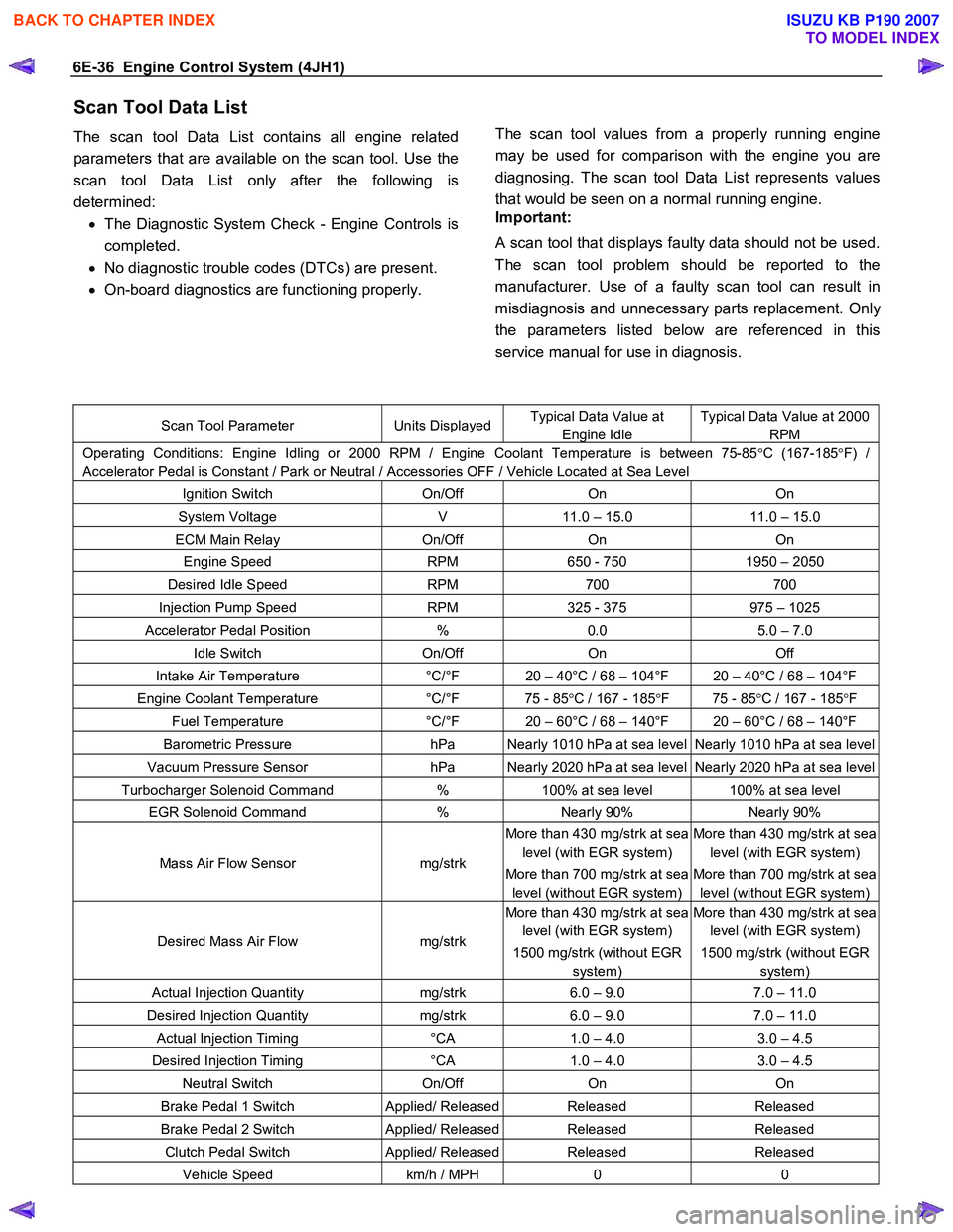
Scan Tool Data List
The scan tool Data List contains all engine related
parameters that are available on the scan tool. Use the
scan tool Data List only after the following is
determined: • The Diagnostic System Check - Engine Controls is
completed.
• No diagnostic trouble codes (DTCs) are present.
• On-board diagnostics are functioning properly.
The scan tool values from a properly running engine
may be used for comparison with the engine you are
diagnosing. The scan tool Data List represents values
that would be seen on a normal running engine.
Important:
A scan tool that displays faulty data should not be used.
The scan tool problem should be reported to the
manufacturer. Use of a faulty scan tool can result in
misdiagnosis and unnecessary parts replacement. Onl
y
the parameters listed below are referenced in this
service manual for use in diagnosis.
Scan Tool Parameter Units DisplayedTypical Data Value at
Engine Idle
Typical Data Value at 2000
RPM
Operating Conditions: Engine Idling or 2000 RPM / Engine Coolant Temperature is between 75-85 °C (167-185 °F) /
Accelerator Pedal is Constant / Park or Neutral / Accessories OFF / Vehicle Located at Sea Level
Ignition Switch On/Off On On
System Voltage V 11.0 – 15.0 11.0 – 15.0
ECM Main Relay On/Off On On
Engine Speed RPM 650 - 750 1950 – 2050
Desired Idle Speed RPM 700 700
Injection Pump Speed RPM 325 - 375 975 – 1025
Accelerator Pedal Position % 0.0 5.0 – 7.0
Idle Switch On/Off On Off
Intake Air Temperature °C/°F 20 – 40°C / 68 – 104°F 20 – 40°C / 68 – 104°F
Engine Coolant Temperature °C/°F 75 - 85 °C / 167 - 185 °F 75 - 85 °C / 167 - 185 °F
Fuel Temperature °C/°F 20 – 60°C / 68 – 140°F 20 – 60°C / 68 – 140°F
Barometric Pressure hPa Nearly 1010 hPa at sea level Nearly 1010 hPa at sea level
Vacuum Pressure Sensor hPa Nearly 2020 hPa at sea level Nearly 2020 hPa at sea level
Turbocharger Solenoid Command % 100% at sea level 100% at sea level
EGR Solenoid Command % Nearly 90% Nearly 90%
Mass Air Flow Sensor mg/strk
More than 430 mg/strk at sea
level (with EGR system)
More than 700 mg/strk at sea
level (without EGR system)
More than 430 mg/strk at sea
level (with EGR system)
More than 700 mg/strk at sea
level (without EGR system)
Desired Mass Air Flow mg/strk
More than 430 mg/strk at sea
level (with EGR system)
1500 mg/strk (without EGR
system)
More than 430 mg/strk at sea
level (with EGR system)
1500 mg/strk (without EGR
system)
Actual Injection Quantity mg/strk 6.0 – 9.0 7.0 – 11.0
Desired Injection Quantity mg/strk 6.0 – 9.0 7.0 – 11.0
Actual Injection Timing °CA 1.0 – 4.0 3.0 – 4.5
Desired Injection Timing °CA 1.0 – 4.0 3.0 – 4.5
Neutral Switch On/Off On On
Brake Pedal 1 Switch Applied/ ReleasedReleased Released
Brake Pedal 2 Switch Applied/ ReleasedReleased Released
Clutch Pedal Switch Applied/ ReleasedReleased Released
Vehicle Speed km/h / MPH 0 0
BACK TO CHAPTER INDEX
TO MODEL INDEX
ISUZU KB P190 2007
Page 1071 of 6020
Engine Control System (4JH1) 6E-37
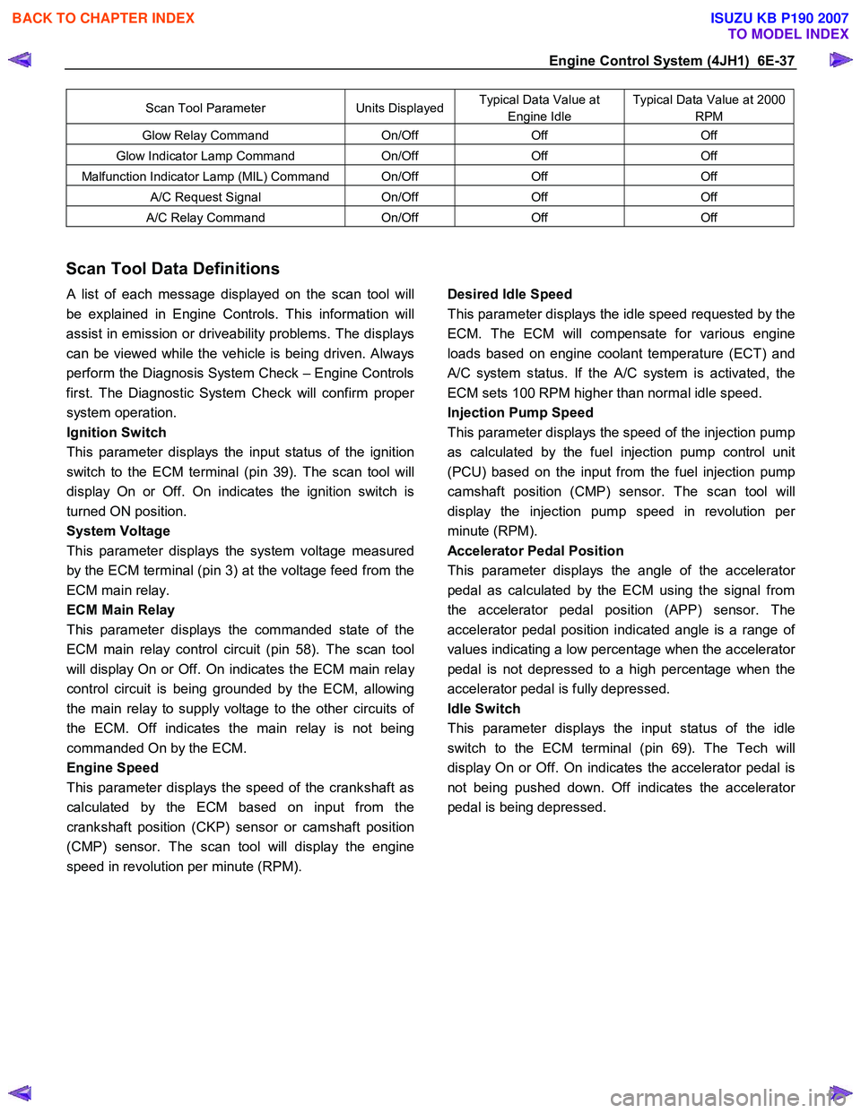
Scan Tool Parameter Units DisplayedTypical Data Value at
Engine Idle
Typical Data Value at 2000
RPM
Glow Relay Command On/Off Off Off
Glow Indicator Lamp Command On/Off Off Off
Malfunction Indicator Lamp (MIL) Command On/Off Off Off
A/C Request Signal On/Off Off Off
A/C Relay Command On/Off Off Off
Scan Tool Data Definitions
A list of each message displayed on the scan tool will
be explained in Engine Controls. This information will
assist in emission or driveability problems. The displays
can be viewed while the vehicle is being driven. Always
perform the Diagnosis System Check – Engine Controls
first. The Diagnostic System Check will confirm prope
r
system operation.
Ignition Switch
This parameter displays the input status of the ignition
switch to the ECM terminal (pin 39). The scan tool will
display On or Off. On indicates the ignition switch is
turned ON position.
System Voltage
This parameter displays the system voltage measured
by the ECM terminal (pin 3) at the voltage feed from the
ECM main relay.
ECM Main Relay
This parameter displays the commanded state of the
ECM main relay control circuit (pin 58). The scan tool
will display On or Off. On indicates the ECM main rela
y
control circuit is being grounded by the ECM, allowing
the main relay to supply voltage to the other circuits o
f
the ECM. Off indicates the main relay is not being
commanded On by the ECM.
Engine Speed
This parameter displays the speed of the crankshaft as
calculated by the ECM based on input from the
crankshaft position (CKP) sensor or camshaft position
(CMP) sensor. The scan tool will display the engine
speed in revolution per minute (RPM).
Desired Idle Speed
This parameter displays the idle speed requested by the
ECM. The ECM will compensate for various engine
loads based on engine coolant temperature (ECT) and
A/C system status. If the A/C system is activated, the
ECM sets 100 RPM higher than normal idle speed.
Injection Pump Speed
This parameter displays the speed of the injection pump
as calculated by the fuel injection pump control unit
(PCU) based on the input from the fuel injection pump
camshaft position (CMP) sensor. The scan tool will
display the injection pump speed in revolution pe
r
minute (RPM).
Accelerator Pedal Position
This parameter displays the angle of the accelerato
r
pedal as calculated by the ECM using the signal from
the accelerator pedal position (APP) sensor. The
accelerator pedal position indicated angle is a range o
f
values indicating a low percentage when the accelerator
pedal is not depressed to a high percentage when the
accelerator pedal is fully depressed.
Idle Switch
This parameter displays the input status of the idle
switch to the ECM terminal (pin 69). The Tech will
display On or Off. On indicates the accelerator pedal is
not being pushed down. Off indicates the accelerato
r
pedal is being depressed.
BACK TO CHAPTER INDEX
TO MODEL INDEX
ISUZU KB P190 2007
Page 1073 of 6020
Engine Control System (4JH1) 6E-39
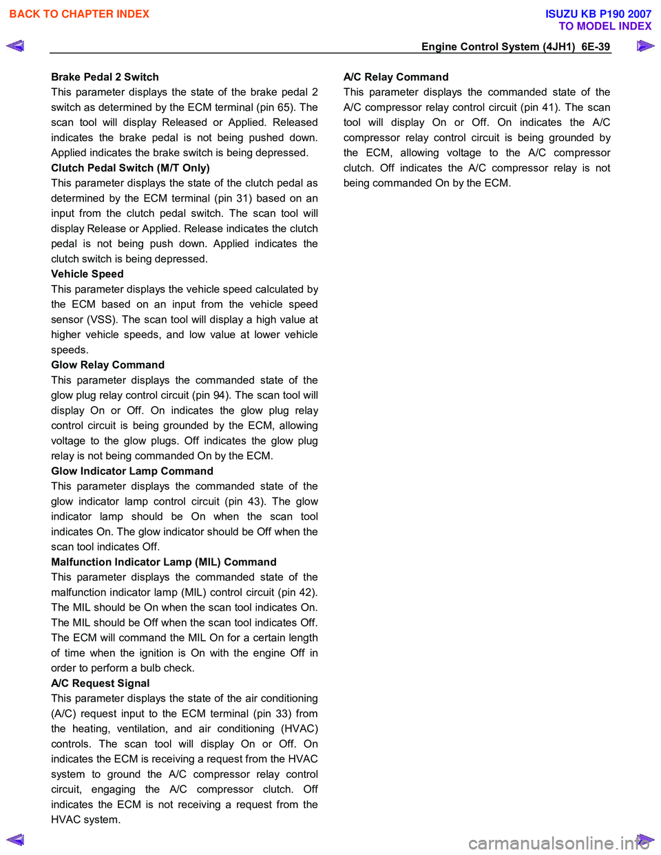
Brake Pedal 2 Switch
This parameter displays the state of the brake pedal 2
switch as determined by the ECM terminal (pin 65). The
scan tool will display Released or Applied. Released
indicates the brake pedal is not being pushed down.
Applied indicates the brake switch is being depressed.
Clutch Pedal Switch (M/T Only)
This parameter displays the state of the clutch pedal as
determined by the ECM terminal (pin 31) based on an
input from the clutch pedal switch. The scan tool will
display Release or Applied. Release indicates the clutch
pedal is not being push down. Applied indicates the
clutch switch is being depressed.
Vehicle Speed
This parameter displays the vehicle speed calculated b
y
the ECM based on an input from the vehicle speed
sensor (VSS). The scan tool will display a high value at
higher vehicle speeds, and low value at lower vehicle
speeds.
Glow Relay Command
This parameter displays the commanded state of the
glow plug relay control circuit (pin 94). The scan tool will
display On or Off. On indicates the glow plug rela
y
control circuit is being grounded by the ECM, allowing
voltage to the glow plugs. Off indicates the glow plug
relay is not being commanded On by the ECM.
Glow Indicator Lamp Command
This parameter displays the commanded state of the
glow indicator lamp control circuit (pin 43). The glo
w
indicator lamp should be On when the scan tool
indicates On. The glow indicator should be Off when the
scan tool indicates Off.
Malfunction Indicator Lamp (MIL) Command
This parameter displays the commanded state of the
malfunction indicator lamp (MIL) control circuit (pin 42).
The MIL should be On when the scan tool indicates On.
The MIL should be Off when the scan tool indicates Off.
The ECM will command the MIL On for a certain length
of time when the ignition is On with the engine Off in
order to perform a bulb check.
A/C Request Signal
This parameter displays the state of the air conditioning
(A/C) request input to the ECM terminal (pin 33) from
the heating, ventilation, and air conditioning (HVAC)
controls. The scan tool will display On or Off. On
indicates the ECM is receiving a request from the HVAC
system to ground the A/C compressor relay control
circuit, engaging the
A/C compressor clutch. Off
indicates the ECM is not receiving a request from the
HVAC system.
A/C Relay Command
This parameter displays the commanded state of the
A/C compressor relay control circuit (pin 41). The scan
tool will display On or Off. On indicates the
A/C
compressor relay control circuit is being grounded b
y
the ECM, allowing voltage to the A/C compressor
clutch. Off indicates the A/C compressor relay is not
being commanded On by the ECM.
BACK TO CHAPTER INDEX
TO MODEL INDEX
ISUZU KB P190 2007
Page 1074 of 6020
6E-40 Engine Control System (4JH1)
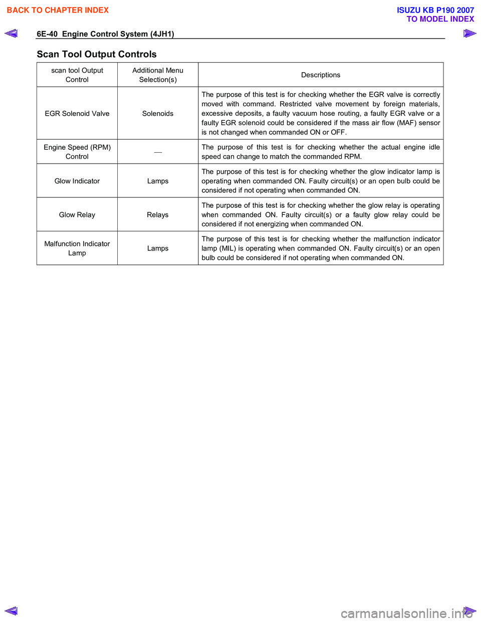
Scan Tool Output Controls
scan tool Output Control Additional Menu
Selection(s) Descriptions
EGR Solenoid Valve Solenoids The purpose of this test is for checking whether the EGR valve is correctly
moved with command. Restricted valve movement by foreign materials,
excessive deposits, a faulty vacuum hose routing, a faulty EGR valve or a
faulty EGR solenoid could be considered if the mass air flow (MAF) sensor
is not changed when commanded ON or OFF.
Engine Speed (RPM) Control
The purpose of this test is for checking whether the actual engine idle
speed can change to match the commanded RPM.
Glow Indicator Lamps The purpose of this test is for checking whether the glow indicator lamp is
operating when commanded ON. Faulty circuit(s) or an open bulb could be
considered if not operating when commanded ON.
Glow Relay Relays The purpose of this test is for checking whether the glow relay is operating
when commanded ON. Faulty circuit(s) or a faulty glow relay could be
considered if not energizing when commanded ON.
Malfunction Indicator Lamp Lamps The purpose of this test is for checking whether the malfunction indicator
lamp (MIL) is operating when commanded ON. Faulty circuit(s) or an open
bulb could be considered if not operating when commanded ON.
BACK TO CHAPTER INDEX
TO MODEL INDEX
ISUZU KB P190 2007
Page 1079 of 6020
Engine Control System (4JH1) 6E-45
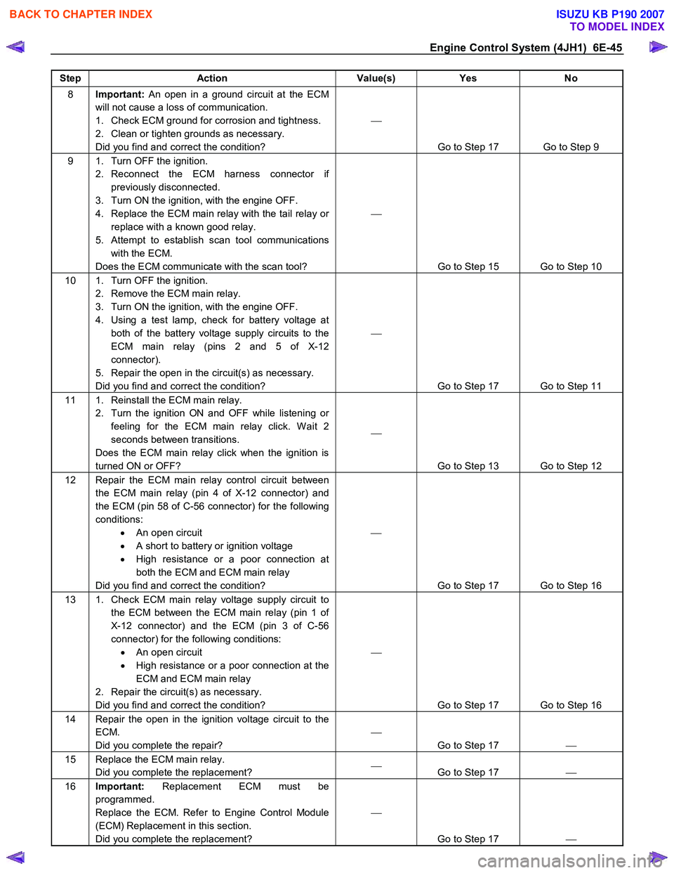
Step Action Value(s) Yes No
8 Important: An open in a ground circuit at the ECM
will not cause a loss of communication.
1. Check ECM ground for corrosion and tightness.
2. Clean or tighten grounds as necessary.
Did you find and correct the condition?
Go to Step 17 Go to Step 9
9 1. Turn OFF the ignition. 2. Reconnect the ECM harness connector if previously disconnected.
3. Turn ON the ignition, with the engine OFF.
4. Replace the ECM main relay with the tail relay or replace with a known good relay.
5. Attempt to establish scan tool communications with the ECM.
Does the ECM communicate with the scan tool?
Go to Step 15 Go to Step 10
10 1. Turn OFF the ignition. 2. Remove the ECM main relay.
3. Turn ON the ignition, with the engine OFF.
4. Using a test lamp, check for battery voltage at both of the battery voltage supply circuits to the
ECM main relay (pins 2 and 5 of X-12
connector).
5. Repair the open in the circuit(s) as necessary.
Did you find and correct the condition?
Go to Step 17 Go to Step 11
11 1. Reinstall the ECM main relay. 2. Turn the ignition ON and OFF while listening or feeling for the ECM main relay click. W ait 2
seconds between transitions.
Does the ECM main relay click when the ignition is
turned ON or OFF?
Go to Step 13 Go to Step 12
12 Repair the ECM main relay control circuit between the ECM main relay (pin 4 of X-12 connector) and
the ECM (pin 58 of C-56 connector) for the following
conditions: • An open circuit
• A short to battery or ignition voltage
• High resistance or a poor connection at
both the ECM and ECM main relay
Did you find and correct the condition?
Go to Step 17 Go to Step 16
13 1. Check ECM main relay voltage supply circuit to the ECM between the ECM main relay (pin 1 of
X-12 connector) and the ECM (pin 3 of C-56
connector) for the following conditions: • An open circuit
• High resistance or a poor connection at the
ECM and ECM main relay
2. Repair the circuit(s) as necessary.
Did you find and correct the condition?
Go to Step 17 Go to Step 16
14 Repair the open in the ignition voltage circuit to the ECM.
Did you complete the repair?
Go to Step 17
15 Replace the ECM main relay.
Did you complete the replacement?
Go to Step 17
16 Important: Replacement ECM must be
programmed.
Replace the ECM. Refer to Engine Control Module
(ECM) Replacement in this section.
Did you complete the replacement?
Go to Step 17
BACK TO CHAPTER INDEX
TO MODEL INDEX
ISUZU KB P190 2007
Page 1090 of 6020
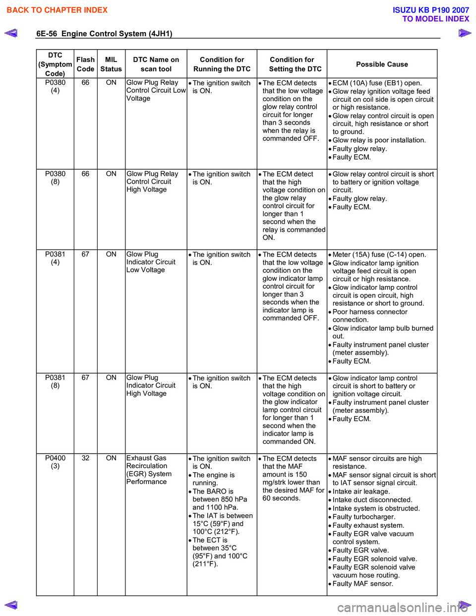
6E-56 Engine Control System (4JH1)
DTC
(Symptom Code) Flash
Code MIL
Status DTC Name on
scan tool Condition for
Running the DTC Condition for
Setting the DTC Possible Cause
P0380
(4) 66 ON Glow Plug Relay
Control Circuit Low
Voltage •
The ignition switch
is ON. •
The ECM detects
that the low voltage
condition on the
glow relay control
circuit for longer
than 3 seconds
when the relay is
commanded OFF.
•
ECM (10A) fuse (EB1) open.
• Glow relay ignition voltage feed
circuit on coil side is open circuit
or high resistance.
• Glow relay control circuit is open
circuit, high resistance or short
to ground.
• Glow relay is poor installation.
• Faulty glow relay.
• Faulty ECM.
P0380 (8) 66 ON
Glow Plug Relay
Control Circuit
High Voltage •
The ignition switch
is ON. •
The ECM detect
that the high
voltage condition on
the glow relay
control circuit for
longer than 1
second when the
relay is commanded
ON.
•
Glow relay control circuit is short
to battery or ignition voltage
circuit.
• Faulty glow relay.
• Faulty ECM.
P0381 (4) 67 ON Glow Plug
Indicator Circuit
Low Voltage •
The ignition switch
is ON.
•
The ECM detects
that the low voltage
condition on the
glow indicator lamp
control circuit for
longer than 3
seconds when the
indicator lamp is
commanded OFF.
•
Meter (15A) fuse (C-14) open.
• Glow indicator lamp ignition
voltage feed circuit is open
circuit or high resistance.
• Glow indicator lamp control
circuit is open circuit, high
resistance or short to ground.
• Poor harness connector
connection.
• Glow indicator lamp bulb burned
out.
• Faulty instrument panel cluster
(meter assembly).
• Faulty ECM.
P0381 (8) 67 ON Glow Plug
Indicator Circuit
High Voltage •
The ignition switch
is ON. •
The ECM detects
that the high
voltage condition on
the glow indicator
lamp control circuit
for longer than 1
second when the
indicator lamp is
commanded ON.
•
Glow indicator lamp control
circuit is short to battery or
ignition voltage circuit.
• Faulty instrument panel cluster
(meter assembly).
• Faulty ECM.
P0400 (3) 32 ON Exhaust Gas
Recirculation
(EGR) System
Performance •
The ignition switch
is ON.
• The engine is
running.
• The BARO is
between 850 hPa
and 1100 hPa.
• The IAT is between
15°C (59°F) and
100°C (212°F).
• The ECT is
between 35°C
(95°F) and 100°C
(211°F).
•
The ECM detects
that the MAF
amount is 150
mg/strk lower than
the desired MAF for
60 seconds.
•
MAF sensor circuits are high
resistance.
• MAF sensor signal circuit is short
to IAT sensor signal circuit.
• Intake air leakage.
• Intake duct disconnected.
• Intake system is obstructed.
• Faulty turbocharger.
• Faulty exhaust system.
• Faulty EGR valve vacuum
control system.
• Faulty EGR valve.
• Faulty EGR solenoid valve.
• Faulty EGR solenoid valve
vacuum hose routing.
• Faulty MAF sensor.
BACK TO CHAPTER INDEX
TO MODEL INDEX
ISUZU KB P190 2007
Page 1092 of 6020
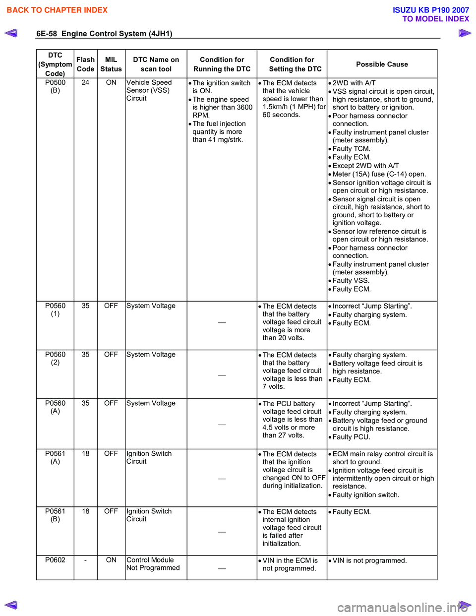
6E-58 Engine Control System (4JH1)
DTC
(Symptom Code) Flash
Code MIL
Status DTC Name on
scan tool Condition for
Running the DTC Condition for
Setting the DTC Possible Cause
P0500
(B) 24 ON Vehicle Speed
Sensor (VSS)
Circuit
•
The ignition switch
is ON.
• The engine speed
is higher than 3600
RPM.
• The fuel injection
quantity is more
than 41 mg/strk.
•
The ECM detects
that the vehicle
speed is lower than
1.5km/h (1 MPH) for
60 seconds.
•
2W D with A/T
• VSS signal circuit is open circuit,
high resistance, short to ground,
short to battery or ignition.
• Poor harness connector
connection.
• Faulty instrument panel cluster
(meter assembly).
• Faulty TCM.
• Faulty ECM.
• Except 2W D with A/T
• Meter (15A) fuse (C-14) open.
• Sensor ignition voltage circuit is
open circuit or high resistance.
• Sensor signal circuit is open
circuit, high resistance, short to
ground, short to battery or
ignition voltage.
• Sensor low reference circuit is
open circuit or high resistance.
• Poor harness connector
connection.
• Faulty instrument panel cluster
(meter assembly).
• Faulty VSS.
• Faulty ECM.
P0560 (1) 35 OFF System Voltage
•
The ECM detects
that the battery
voltage feed circuit
voltage is more
than 20 volts.
•
Incorrect “Jump Starting”.
• Faulty charging system.
• Faulty ECM.
P0560 (2) 35 OFF System Voltage
•
The ECM detects
that the battery
voltage feed circuit
voltage is less than
7 volts.
•
Faulty charging system.
• Battery voltage feed circuit is
high resistance.
• Faulty ECM.
P0560 (A) 35 OFF System Voltage
•
The PCU battery
voltage feed circuit
voltage is less than
4.5 volts or more
than 27 volts.
•
Incorrect “Jump Starting”.
• Faulty charging system.
• Battery voltage feed or ground
circuit is high resistance.
• Faulty PCU.
P0561 (A) 18 OFF Ignition Switch
Circuit
•
The ECM detects
that the ignition
voltage circuit is
changed ON to OFF
during initialization.
•
ECM main relay control circuit is
short to ground.
• Ignition voltage feed circuit is
intermittently open circuit or high
resistance.
• Faulty ignition switch.
P0561 (B) 18 OFF Ignition Switch
Circuit
•
The ECM detects
internal ignition
voltage feed circuit
is failed after
initialization.
•
Faulty ECM.
P0602 - ON Control Module
Not Programmed
•
VIN in the ECM is
not programmed. •
VIN is not programmed.
BACK TO CHAPTER INDEX
TO MODEL INDEX
ISUZU KB P190 2007