Neutral switch ISUZU KB P190 2007 Workshop Workshop Manual
[x] Cancel search | Manufacturer: ISUZU, Model Year: 2007, Model line: KB P190, Model: ISUZU KB P190 2007Pages: 6020, PDF Size: 70.23 MB
Page 3724 of 6020

Powertrain Interface Module – V6 Page 6E1–63
PRND32L Display Diagnostic Table
Step Action Yes No
1
Has the Diagnostic System Check been performed?
Go to Step 2 Refer to
Diagnostic
System Check in this section
2 1 Turn the ignition to the ON position.
2 Move the gear select lever through each gear position and check the instrument cluster PRND32L display.
Does each indicator display an off to on condition? Refer to Additional
Information in this section Go to Step 3
3
Are any of the indicators permanently illuminated? Go to Step 5 Go to Step 4
4 1 Using Tech 2 select,
Body / PIM / Miscellaneous Tests / Status Indicators /
PRNDL Lamps.
2 Using the Tech 2 soft keys step through the sequence of illuminating each PRND32L indicator in turn.
Does each indicator display an off to on condition? Go to Step 8 Go to Step 10
5
Disconnect the TCM harness connector. Refer to 7C4 Automatic
Transmission – 4L60E – On-vehicle Servicing.
Is the indicator in Step 3 still permanently illuminated? Go to Step 6 Go to Step 8
6 Disconnect the PIM harness connector. Refer to 11.2 Powertrain
Interface Module in this Section.
Is the indicator in Step 3 still permanently illuminated? Go to Step 7 Go to Step 14
7
Turn the ignition to the ON position, test for a short to voltage of the
relevant circuits from the PIM to the instrument cluster. Refer to 6
W iring Diagram and Connector Chart.
W as any fault found and rectified? Go to step 15 Go to step 12
8
Check the neutral start and back-up lamp switch and automatic
transmission for correct operation. Refer to 7C2 Automatic
Transmission – 4L60E – Electrical Diagnosis.
W as any fault found and rectified? Go to Step 15 Go to 9
9 Replace the TCM. Refer to 7C4 Automatic Transmission – 4L60E –
On-vehicle Servicing.
Has the repair been completed? Go to Step 15 —
10 1 Disconnect the instrument cluster harness connector.
2 Turn the ignition to the ON position.
3 W hile sequencing each PRND32L indicator, back probe the relevant connector pins at the rear of the instrument cluster.
Refer to 6 W iring Diagram and Connector Chart.
Does the multimeter display a change from 0 to 10 Volts as each
PRND32L indicator position is selected? Go to Step 12 Go to 11
11 Test for high resistance, open circuit, a short to ground of the relevant
circuits from the PIM to the instrument cluster. Refer to 6 W iring
Diagram and Connector Chart.
W as any fault found and rectified? Go to Step 15 Go to Step 14
BACK TO CHAPTER INDEX
TO MODEL INDEX
ISUZU KB P190 2007
Page 3768 of 6020
Automatic Transmission – 4L60E – General Information Page 7C1–8
2.4 System Protection Devices
Should 1st gear be selected and left in that range, the TCM will protect the engine from an over-speeding condition by
upshifting to 2nd gear at a pre-determined point. Similarly, the TCM provides high speed, downshift protection by
preventing a manual shift into 1st gear above pre-determined engine speeds.
Under severe operating conditions such as towing in high ambient temperatures, fluid temperatures can rise to a point
where lubrication breakdown can occur. In addition to having an oil cooler fitted to the vehicle, the 4L60E transmission is
also fitted with a transmission fluid temperature sensor located in the Transmission Range (TR) Pressure Switch
Assembly (PSA).
When fluid temperatures in excess of 135 °C are sensed, the torque converter clutch is applied as programmed, in 3rd or
4th gear. This action reduces further the fluid temperature during normal operation of the torque converter. While these
high fluid temperatures are sensed however, torque converter clutch apply is not available when the throttle opening is
above 50%.
Similarly, when the fluid temperature is below 29 °C, the TCM prevents torque converter clutch apply.
If a condition occurs, preventing electronic control of the transmission's functions, a 'Fail Safe' mode will default the
transmission to 3rd gear when either Drive or 3 is selected, applying also maximum line pressure. W hile in this mode, the
vehicle operator can still manually select 2, 1, Reverse, Park or Neutral, should the need arise.
2.5 Self Diagnosis
If any transmission operation controlled by the TCM begins to operate outside its pre-set parameters, the TCM has the
ability to store a range of diagnostic codes which can be accessed by the servicing technician, thereby localising the
problem.
2.6 TCM Sensors and Actuators
As indicated earlier, there are a number of sensors and switches providing input information for the TCM programming
that will allow the TCM to change the shift pattern, shift feel and torque converter clutch operation.
The TCM does this by comparing this input information with its predetermined values on shift pattern, fluid pressure
maps, shift duration parameters, extreme heat protection programming and adaptive controls.
In addition, each input signal and output actuator operation is also monitored and if outside its pre-set parameters, a
diagnostic code is logged for future reference by the servicing technician.
BACK TO CHAPTER INDEX
TO MODEL INDEX
ISUZU KB P190 2007
Page 3769 of 6020
Automatic Transmission – 4L60E – General Information Page 7C1–9
3 Transmission Control Module
Operation Overview
3.1 Transmission Control Module
W ith the introduction of the new HFV6 engine, the powertrain architecture has been redesigned to accommodate this
introduction. W ith this design, a new bus architecture and protocol has also been introduced. The new bus connects the
following modules:
• engine control module (ECM),
• transmission control module (TCM),
• powertrain interface module (PIM) and
• ABS module.
The protocol used to communicate between these modules is called General Motors Local Area Network (GM LAN)
which is based on Controller Area Network (CAN) communication protocol. For further information on GM LAN protocol
and data bus structure, refer to 6E1 Powertrain Interface Module – V6.
Component Location
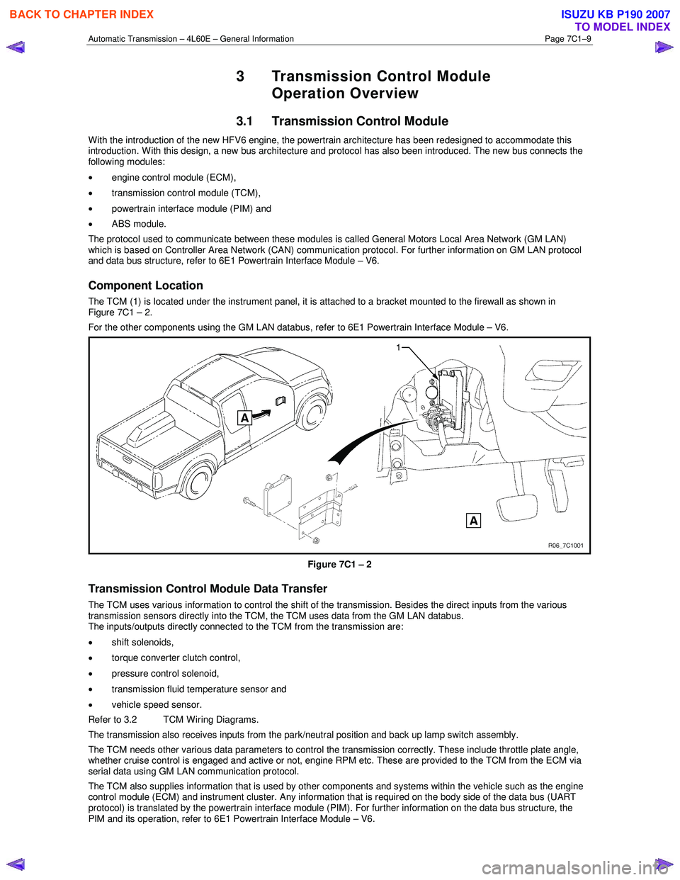
The TCM (1) is located under the instrument panel, it is attached to a bracket mounted to the firewall as shown in
Figure 7C1 – 2.
For the other components using the GM LAN databus, refer to 6E1 Powertrain Interface Module – V6.
Figure 7C1 – 2
Transmission Control Module Data Transfer
The TCM uses various information to control the shift of the transmission. Besides the direct inputs from the various
transmission sensors directly into the TCM, the TCM uses data from the GM LAN databus.
The inputs/outputs directly connected to the TCM from the transmission are:
• shift solenoids,
• torque converter clutch control,
• pressure control solenoid,
• transmission fluid temperature sensor and
• vehicle speed sensor.
Refer to 3.2 TCM Wiring Diagrams.
The transmission also receives inputs from the park/neutral position and back up lamp switch assembly.
The TCM needs other various data parameters to control the transmission correctly. These include throttle plate angle,
whether cruise control is engaged and active or not, engine RPM etc. These are provided to the TCM from the ECM via
serial data using GM LAN communication protocol.
The TCM also supplies information that is used by other components and systems within the vehicle such as the engine
control module (ECM) and instrument cluster. Any information that is required on the body side of the data bus (UART
protocol) is translated by the powertrain interface module (PIM). For further information on the data bus structure, the
PIM and its operation, refer to 6E1 Powertrain Interface Module – V6.
BACK TO CHAPTER INDEX
TO MODEL INDEX
ISUZU KB P190 2007
Page 3776 of 6020
Automatic Transmission – 4L60E – General Information Page 7C1–16
6 Torque Specifications
Oil pan attaching bolt ............................................................................ 12.0 Nm
Shift selector base plate attaching nut ................................................... 7.0 Nm
Spring plate attaching screw .................................................................. 2.0 Nm
Selector lever knob attaching screw ....................................................... 2.0 Nm
Selector cable bracket attaching bolt.................................................... 22.0 Nm
Heat shield front attaching screw .............................................. 15.0 – 35.0 Nm
Heat shield rear attaching screw ............................................................ 9.0 Nm
Manual shaft linkage attaching nut ...................................................... 25.0 Nm
Neutral start and back-up lamp switch attaching screw............. 15.0 – 35.0 Nm
Vehicle speed sensor attaching bolt ........................................... 11.0 - 14.0 Nm
Transmission mount attaching bolt ...................................................... 50.0 Nm
Transmission support attaching bolt and nut ............................. 50.0 – 65.0 Nm
Transmission mount attaching nut ....................................................... 52.0 Nm
Heat shield to transmission support attaching bolt ............................... 52.0 Nm
Extension housing attaching bolt ............................................... 42.0 – 48.0 Nm
1 – 2 Accumulator cover attaching bolt................................................. 12.0 Nm
TCC solenoid attaching bolt ................................................................. 12.0 Nm
Control valve body attaching bolt ......................................................... 12.0 Nm
Transmission fluid pressure (TFP) manual valve
position switch attaching bolt ................................................................ 12.0 Nm
Manual detent spring attaching bolt ...................................................... 23.0 Nm
Spacer plate support plate attaching bolt ............................................. 12.0 Nm
Filler tube bracket attaching bolt................................................ 20.0 – 35.0 Nm
Vent pipe attaching bolt .......................................................................... 6.0 Nm
Transmission cooler lines bracket attaching screw .............................. 23.0 Nm
Torque converter housing attaching bolt ................................... 52.0 – 66.0 Nm
Torque converter to flexplate attaching bolt............................... 60.0 – 70.0 Nm
Torque converter cover attaching bolt ....................................... 12.0 – 16.0 Nm
TCM bracket attaching nut ..................................................................... 7.0 Nm
TCM attaching bolt and nut .................................................................... 7.0 Nm
Oil Pump Cover to Pump Body Attaching Bolt...................................... 25.0 Nm
Pressure Control Solenoid Retainer Attaching Bolt .............................. 12.0 Nm
Forward Accumulator Cover Attaching Bolt .......................................... 12.0 Nm
Oil Pump to Transmission Case Attaching Bolt .................................... 30.0 Nm
Torque Converter Housing to
Transmission Case Attaching Bolt............................................. 65.0 – 75.0 Nm
BACK TO CHAPTER INDEX
TO MODEL INDEX
ISUZU KB P190 2007
Page 3803 of 6020

Automatic Transmission – 4L60E – Electrical Diagnosis Page 7C2–17
Tech 2 Parameter Units Displayed Typical Data Value
High Side Driver 1 N/A N/A
TCC Solenoid On / Off Varies
TCC PWM Solenoid Percent 0%
TCC Slip Speed RPM +/-50 RPM from Engine Speed
Transmission Range (TR) Park/Neutral, Reverse, Drive4,
Drive3, Drive2, Drive1 or Invalid Park/Neutral
TR Switch A
Open 12 V / Closed 0 V Varies
TR Switch B Open 12 V / Closed 0 V Varies
TR Switch C Open 12 V / Closed 0 V Varies
TR Switch P Open 12 V / Closed 0 V Varies
Latest Shift Seconds Varies
1-2 Shift Time Seconds Varies
2-3 Shift Time Seconds Varies
3-4 Shift Time Seconds Varies
Cruise Control Active / Inactive Varies
A/C Clutch On / Off Varies
Ignition Voltage Volts 12-14 V
Shift Pattern Normal / Power / Cruise Varies
4 Wheel Drive Low Active / Inactive Inactive
TCC Data
Once this mode is selected, displays specific parameter information about the torque converter clutch controlling devices
and their circuits.
TCC Data Parameters
For definitions of the parameters in this table, refer to 3.3 Tech 2 Data Definitions.
Tech 2 Parameter Units Displayed Typical Data Value
TCC Solenoid On / Off Varies
TCC PWM Solenoid Percent 0%
TCC Slip Speed RPM +/-50 RPM from Engine Speed
TCC Duty Cycle Circuit Open or Shorted / Short to Battery /
Okay Okay
Throttle Position
Percent Varies
Engine Speed RPM Varies
AT Input Speed N/A N/A
AT Output Speed RPM Varies
Engine Torque Nm Varies
Vehicle Speed km/h 0
Commanded Gear 1,2,3,4 1
Engine Coolant Temperature °C Varies
BACK TO CHAPTER INDEX
TO MODEL INDEX
ISUZU KB P190 2007
Page 3809 of 6020
Automatic Transmission – 4L60E – Electrical Diagnosis Page 7C2–23
TFP Gear: This parameter displays Park/Neutral, Reverse , Drive4 , Drive3 , Drive2 , Drive1 or Invalid . This parameter
is the decoded status of the three A/B/C inputs from the automatic transmission fluid pressure manual valve position
switch. If a valid combination of inputs is not detected, invalid will be displayed.
TFP Swi A/B/C: This parameter displays Open 12 V / Closed 0 V for each switch. This parameter indicates the statues
of the three inputs from the automatic transmission fluid pressure manual valve position switch assembly.
Throttle Position: This parameter displays a calculated value, which is determined by the accelerator pedal position and
the actual throttle position, used to optimise transmission controls. It represents the driver’s intended requested for
torque or acceleration. The range is 0-100%, 0% represents an idle or coast request and 100% represents a request for
wide open throttle (WOT).
Torque Converter Efficiency: This parameter displays a ratio of 0.00:1 to 2:1. The ratio is calculates by multiplying the
speed ratio by a value related to the ‘K factor’ of the torque converter. The ‘K factor’ is the looseness or tightness of the
torque converter for a given torque. The nearer the torque converter is to full coupling, i.e. 1:1, the closer the torque
converter efficiency number will be to 1.
TR Switch A/B/C/P: This parameter displays the status of the four inputs from the transmission range switch. Tech 2
displays Open 12V / Closed 0 V . Open 12 V indicates an ignition voltage input to the control module. Closed 0 V
indicates a zero voltage input to the control module.
Transmission Fluid Temperature: This parameter displays the input signal of the transmission fluid temperature sensor.
Transmission fluid temperature is high, 151°C, when signal voltage is low, 0 V. Transmission fluid temperature is low, -
40°C, when signal voltage is high, 5 V.
Transmission Hot Mode: This parameter displays the automatic transmission fluid temperature (TFT) and displays On
or Off . Off indicates the TFT has not exceeded 130°C. On indicates the TFT has exceeded 130°C and has not cooled to
120°C for greater than 5 seconds. These numbers are approximate and differ with transmissions.
Vehicle Speed: This parameter displays the speed at which the vehicle is travelling. Tech 2 displays vehicle speed as
kilometres per hour (km/h). The vehicle speed is calculates based on the input signal from the automatic transmission
output shaft speed sensor.
3.4 Miscellaneous Tests
Tech 2
Miscellaneous Tests Description
Shift Solenoid A •
The TCM commands the 1-2 shift solenoid valve on and off. Tech 2’s Shift Solenoid A
Parameter should match the commanded state. Tech 2’s Commanded Gear
parameter should correspond with the shift solenoid combination. Refer to
5.6 Shift Solenoid Valve State and Gear Ratio.
• When the ignition is on, and the engine is off, there no limits to this control. The
solenoid remains on until commanded off, and vice versa. W hen the test is exited, the
solenoid state is determined by the TCM.
• W hen the engine is running, the following control limits apply:
• Only sequential gear changes are allowed. For example, 1
st to 3rd is not allowed.
If a non-sequential gear change is attempted, the message Non-sequential
gear changes not allowed . Gear changes must be made in order appears
on Tech 2.
• The vehicle speed must be below a calibrated value. If the vehicle speed is too
high, the message Vehicle speed too high appears on Tech 2.
• The engine speed must be below a calibrated value. If the engine speed is too
high, the message Engine speed too high appears on Tech 2.
• Downshifts are allowed only when the vehicle speed is below a calibrated value.
If the vehicle speed is too high, the message Eng. is on and veh. speed to hi
for 3-2 or 2-1 downshift appears on Tech 2.
• The gear requested may not be greater than the current selected transmission
range (PRNDL). For example, 3
rd gear is not allowed if the transmission range is
D2. If the gear requested is greater than the current selected transmission
range, the message Eng. running and gear request is greater than the
current TR appears on Tech 2.
• The solenoid remains on until commanded off, and vice versa. W hen the test is
exited, the solenoid state is determined by the TCM.
BACK TO CHAPTER INDEX
TO MODEL INDEX
ISUZU KB P190 2007
Page 3819 of 6020
Automatic Transmission – 4L60E – Electrical Diagnosis Page 7C2–33
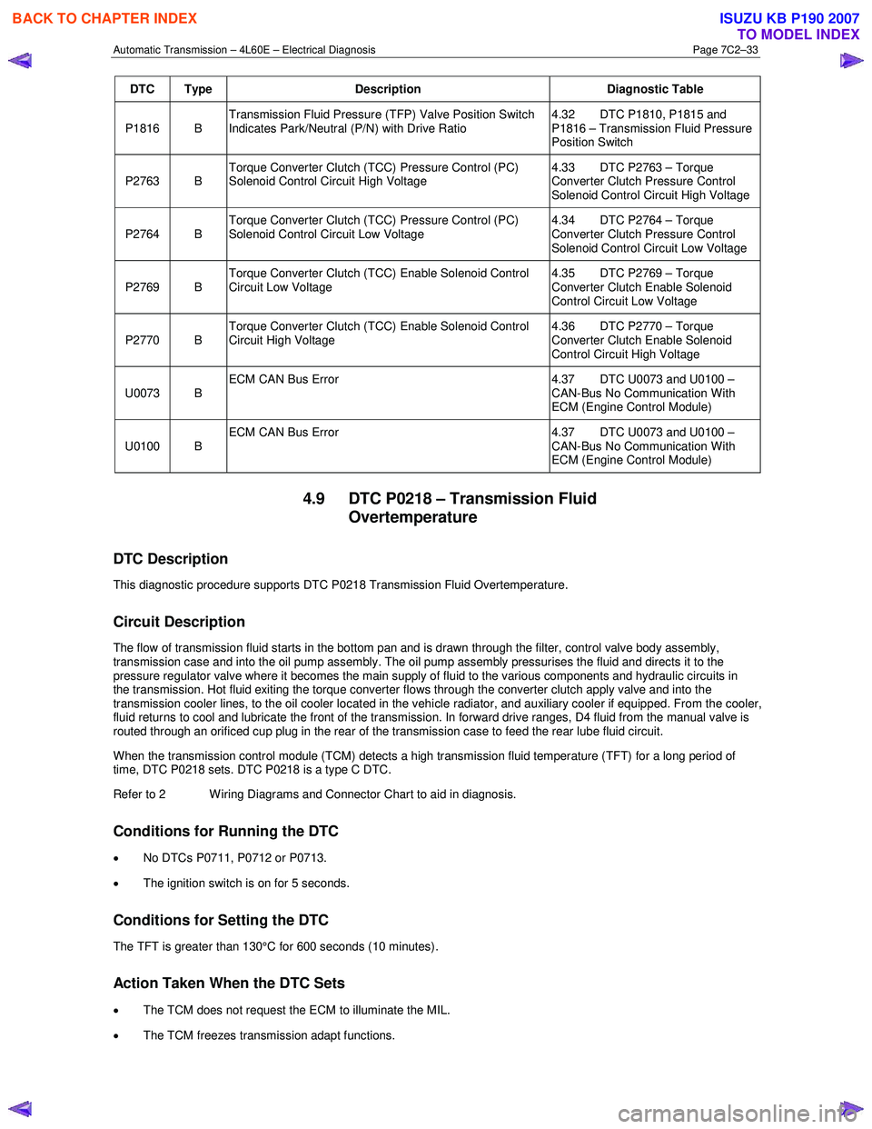
DTC Type Description Diagnostic Table
P1816 B Transmission Fluid Pressure (TFP) Valve Position Switch
Indicates Park/Neutral (P/N) with Drive Ratio 4.32 DTC P1810, P1815 and
P1816 – Transmission Fluid Pressure
Position Switch
P2763 B Torque Converter Clutch (TCC) Pressure Control (PC)
Solenoid Control Circuit High Voltage 4.33 DTC P2763 – Torque
Converter Clutch Pressure Control
Solenoid Control Circuit High Voltage
P2764 B Torque Converter Clutch (TCC) Pressure Control (PC)
Solenoid Control Circuit Low Voltage 4.34 DTC P2764 – Torque
Converter Clutch Pressure Control
Solenoid Control Circuit Low Voltage
P2769 B Torque Converter Clutch (TCC) Enable Solenoid Control
Circuit Low Voltage 4.35 DTC P2769 – Torque
Converter Clutch Enable Solenoid
Control Circuit Low Voltage
P2770 B Torque Converter Clutch (TCC) Enable Solenoid Control
Circuit High Voltage 4.36 DTC P2770 – Torque
Converter Clutch Enable Solenoid
Control Circuit High Voltage
U0073 B ECM CAN Bus Error
4.37 DTC U0073 and U0100 –
CAN-Bus No Communication With
ECM (Engine Control Module)
U0100 B ECM CAN Bus Error
4.37 DTC U0073 and U0100 –
CAN-Bus No Communication With
ECM (Engine Control Module)
4.9 DTC P0218 – Transmission Fluid Overtemperature
DTC Description
This diagnostic procedure supports DTC P0218 Transmission Fluid Overtemperature.
Circuit Description
The flow of transmission fluid starts in the bottom pan and is drawn through the filter, control valve body assembly,
transmission case and into the oil pump assembly. The oil pump assembly pressurises the fluid and directs it to the
pressure regulator valve where it becomes the main supply of fluid to the various components and hydraulic circuits in
the transmission. Hot fluid exiting the torque converter flows through the converter clutch apply valve and into the
transmission cooler lines, to the oil cooler located in the vehicle radiator, and auxiliary cooler if equipped. From the cooler ,
fluid returns to cool and lubricate the front of the transmission. In forward drive ranges, D4 fluid from the manual valve is
routed through an orificed cup plug in the rear of the transmission case to feed the rear lube fluid circuit.
When the transmission control module (TCM) detects a high transmission fluid temperature (TFT) for a long period of
time, DTC P0218 sets. DTC P0218 is a type C DTC.
Refer to 2 W iring Diagrams and Connector Chart to aid in diagnosis.
Conditions for Running the DTC
• No DTCs P0711, P0712 or P0713.
• The ignition switch is on for 5 seconds.
Conditions for Setting the DTC
The TFT is greater than 130°C for 600 seconds (10 minutes).
Action Taken When the DTC Sets
•
The TCM does not request the ECM to illuminate the MIL.
• The TCM freezes transmission adapt functions.
BACK TO CHAPTER INDEX
TO MODEL INDEX
ISUZU KB P190 2007
Page 3889 of 6020

Automatic Transmission – 4L60E – Electrical Diagnosis Page 7C2–103
Step Action Yes No
6 Using a multimeter, test between E-95 pin 3 and C-96 pin 30 for a
short to voltage.
Did you find and correct the condition? Go to Step 8 Go to Step 7
7 Replace the TCM, refer to 7C4 Automatic Transmission – 4L60E –
On-vehicle Servicing
Did you complete the replacement? Go to Step 8 —
8 Perform the following procedure to verify the repair:
1 On Tech 2 select: Diagnostic Trouble Codes / Clear Engine & Transmission
DTCs.
2 Follow the instructions on Tech 2 and clear any DTCs.
3 On Tech 2 select: Data Display / 2-3 Shift Data.
4 Drive the vehicle in D4 and ensure the following conditions are met::
• The TCM commands the Shift Solenoid B On and the
Shift Solenoid B Circuit status parameter displays Okay.
• The TCM commands the Shift Solenoid B Off and the
Shift Solenoid B Circuit status parameter displays Okay.
• All conditions are met for 5 seconds.
4 On Tech 2 select:
Diagnostic Trouble Codes / Read DTC Information.
Has DTC P0977 set? Go to Step 2 Go to Step 9
9 On Tech 2 select:
Diagnostic Trouble Codes / Read DTC Information.
Does Tech 2 display any DTCs you have not diagnosed? Refer to
4.8 Diagnostic Trouble Code List System OK
When all diagnosis and repairs are completed, check the
system for correct operation.
4.32 DTC P1810, P1815 and P1816 –
Transmission Fluid Pressure Position
Switch
DTC Description
This diagnostic procedure supports the following DTCs:
• DTC P1810 Transmission Fluid Pressure (TFP) Position Switch Circuit.
• DTC P1815 Transmission Fluid Pressure (TFP) Valve Position Switch – Start in W rong Range.
• DTC P1816 Transmission Fluid Pressure (TFP) Valve Position Switch Indicates Park/Neutral (P/N) with Drive Ratio.
Circuit Description
The automatic transmission fluid pressure (TFP) manual valve position switch consists of five pressure switches
(two normally-closed and three normally-open) and a transmission fluid temperature (TFT) sensor combined into one unit.
The combined unit mounts on the valve body. The transmission control module (TCM) supplies ignition voltage for each
range signal. By grounding one or more of these circuits through various combinations of the pressure switches, the
TCM detects which manual valve position you select. The TCM compares the actual voltage combination of the switches
to a TFP manual valve position switch combination chart stored in memory.
The TFP manual valve position switch cannot distinguish between park and neutral because the monitored valve body
pressures are identical. W ith the engine off and the ignition switch on, the TFP manual valve position switch indicates
BACK TO CHAPTER INDEX
TO MODEL INDEX
ISUZU KB P190 2007
Page 3890 of 6020

Automatic Transmission – 4L60E – Electrical Diagnosis Page 7C2–104
park/neutral. Disconnecting connector E-95 from the transmission removes the ground potential for the three range
signals to the TCM. In this case, with the engine off, and the ignition switch on, D2 will be indicated.
When the TCM detects an invalid state of the TFP manual valve position switch circuit by deciphering the TFP manual
valve position switch inputs, then either DTC P1810, P1815 or P1816 sets. All theses DTCs are a type B DTC.
Refer to 2 W iring Diagrams and Connector Chart to aid in diagnosis.
Conditions for Running the DTC
DTC P1810
• The system voltage is 8 – 18 V.
• The engine speed is greater than 500 r.p.m. for 5 seconds.
DTC P1815
•
No DTCs P0722 or P0723.
• The system voltage is 8 – 18 V.
• The engine speed is less than 50 r.p.m., then 50 – 650 r.p.m. for 0.75 seconds, then greater than 650 r.p.m. for
5 seconds.
• Output shaft speed less than 250 r.p.m.
DTC P1816
• No DTCs P0722 or P0723.
• The system voltage is 8 – 18 V.
• The engine speed is less than 50 r.p.m., then 50 – 650 r.p.m. for 0.75 seconds, then greater than 650 r.p.m. for
5 seconds.
• Output shaft speed less than 250 r.p.m.
Conditions for Setting the DTC
DTC P1810
DTC P1810 sets when the TCM detects an invalid TFP manual valve position switch state for 60 seconds.
DTC P1815
DTC P1815 sets when the TCM detects D2 only, TFP manual valve position switch state after engine start for 7 seconds.
DTC P1816
DTC P1816 sets when the TCM detects one of the following conditions for 13 seconds:
• park/neutral indicated with a 1st gear ratio,
• park/neutral indicated with a 2nd gear ratio,
• park/neutral indicated with a 3rd gear ratio, or
• park/neutral indicated with a 4th gear ratio.
Action Taken When the DTC Sets
• The TCM requests the ECM to illuminate the MIL during the second consecutive trip in which the conditions for
setting the DTC are met.
• The TCM commands maximum line pressure.
• The TCM freezes transmission adaptive functions.
• The TCM inhibits TCC engagement.
BACK TO CHAPTER INDEX
TO MODEL INDEX
ISUZU KB P190 2007
Page 3911 of 6020
Automatic Transmission – 4L60E – Electrical Diagnosis Page 7C2–125
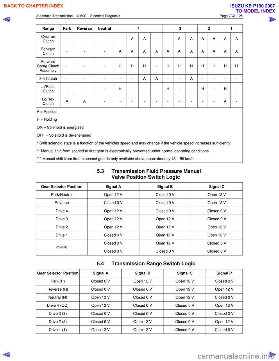
Range Park Reverse Neutral 4 3 2 1
Overrun
Clutch - - - - A A - - A A A A A A
Forward
Clutch - - - A A A A A A A A A A A
Forward
Sprag Clutch Assembly - - - H H H - H H H H H H H
3-4 Clutch - - - - - A A - - A - - - -
Lo/Roller
Clutch - - - H - - - H - - H - H -
Lo/Rev
Clutch A A - - - - - - - - - - A -
A = Applied
H = Holding
ON = Solenoid is energised
OFF = Solenoid is de-energised
* Shift solenoid state is a function of the vehicles speed and may change if the vehicle speed increases sufficiently
** Manual shift from second to first gear is electronically prevented under normal operating conditions
*** Manual shift from first to second gear is only available above approximately 48 – 56 km/h
5.3 Transmission Fluid Pressure Manual Valve Position Switch Logic
Gear Selector Position Signal A Signal B Signal C
Park/Neutral Open 12 V Closed 0 V Open 12 V
Reverse Closed 0 V Closed 0 V Open 12 V
Drive 4 Open 12 V Closed 0 V Closed 0 V
Drive 3 Open 12 V Open 12 V Closed 0 V
Drive 2 Open 12 V Open 12 V Open 12 V
Drive 1 Closed 0 V Open 12 V Open 12 V
Closed 0 V Open 12 V Closed 0 V Invalid
Closed 0 V Closed 0 V Closed 0 V
5.4 Transmission Range Switch Logic
Gear Selector Position Signal A Signal B Signal C Signal P
Park (P) Closed 0 V Open 12 V Open 12 V Closed 0 V
Reverse (R) Closed 0 V Closed 0 V Open 12 V Open 12 V
Neutral (N) Open 12 V Closed 0 V Open 12 V Closed 0 V
Drive 4 (OD) Open 12 V Closed 0 V Closed 0 V Open 12 V
Drive 3 (3) Closed 0 V Closed 0 V Closed 0 V Closed 0 V
Drive 2 (2) Closed 0 V Open 12 V Closed 0 V Open 12 V
Drive 1 (1) Open 12 V Open 12 V Closed 0 V Closed 0 V
BACK TO CHAPTER INDEX
TO MODEL INDEX
ISUZU KB P190 2007