indicator ISUZU KB P190 2007 Workshop Owner's Manual
[x] Cancel search | Manufacturer: ISUZU, Model Year: 2007, Model line: KB P190, Model: ISUZU KB P190 2007Pages: 6020, PDF Size: 70.23 MB
Page 846 of 6020
ENGINE MECHANICAL 6A – 41
Coolant Replenishment
Warning:
When the coolant is heated to a high temperature, be
sure not to loosen or remove the rediator cap.
Otherwise you might get scalded by hot vapor or
boiling water.
To open the radiator cap, put a piece of thick cloth on
the cap and loosen the cap slowly to reduce the
pressure when the coolant has become cooler.
1. Open rediator cap pour coolant up to filler neck
2. Pour coolant into reservoir tank up to "MAX" line
3. Tighten radiator cap and start the engine. After idling for 2 to 3 minutes, stop the engine and reopen radiator
cap. If the water level is lower, replenish.
4. After replenish the coolant tighten radiator cap, warm up the engine at about 2000 rpm. Set heater
adjustment to the highest temperature position, and let
the coolant circulate also into heater water system.
5. Check to see the thermometer, continuously idling 5 minutes and stop the engine.
6. W hen the engine has been cooled, check filler neck for water level and replenish if required. Should extreme
shortage of coolant is found, check the coolant system
and reservoir tank hose for leakage.
7. Pour coolant into the reservoir tank up to "MAX" line.
Coolant Capacity lit (US/UK gal)
4JA1 / TC 9.4 (2.5 / 2.1)
4JH1TC M/T: 10.1 (2.7 / 2.2)
A/T: 10.0 (2.6 / 2.2)
Engine Warm-Up
After completing the required maintenance procedures,
start the engine and allow it to idle until it is warm.
Check the following:
1. Engine idling speed.
2. Engine noise level.
3. Engine lubricating system and cooling system. Carefully check for oil and coolant leakage.
4. Clutch engagement.
5. Transmission operation.
6. Indicator warning light operation.
BACK TO CHAPTER INDEX
TO MODEL INDEX
ISUZU KB P190 2007
Page 856 of 6020
ENGINE MECHANICAL 6A – 51
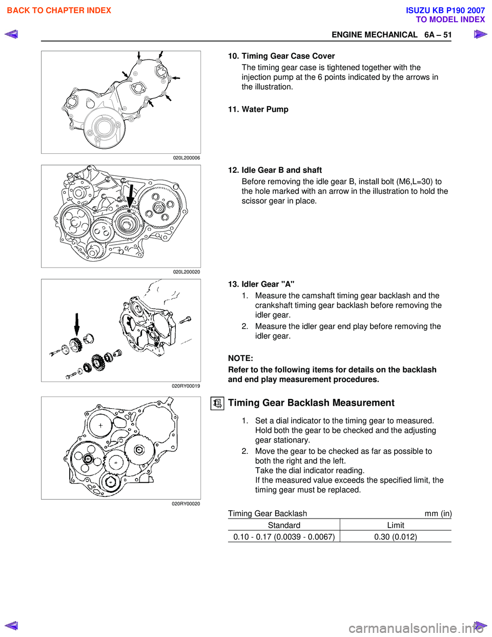
10. Timing Gear Case Cover The timing gear case is tightened together with the
injection pump at the 6 points indicated by the arrows in
the illustration.
11. Water Pump
12. Idle Gear B and shaft Before removing the idle gear B, install bolt (M6,L=30) to
the hole marked with an arrow in the illustration to hold the
scissor gear in place.
13. Idler Gear "A" 1. Measure the camshaft timing gear backlash and the crankshaft timing gear backlash before removing the
idler gear.
2. Measure the idler gear end play before removing the idler gear.
NOTE:
Refer to the following items for details on the backlash
and end play measurement procedures.
Timing Gear Backlash Measurement
1. Set a dial indicator to the timing gear to measured. Hold both the gear to be checked and the adjusting
gear stationary.
2. Move the gear to be checked as far as possible to both the right and the left.
Take the dial indicator reading.
If the measured value exceeds the specified limit, the
timing gear must be replaced.
Timing Gear Backlash mm (in)
Standard Limit
0.10 - 0.17 (0.0039 - 0.0067) 0.30 (0.012)
020L200006
020L200020
020RY00019
020RY00020
BACK TO CHAPTER INDEX
TO MODEL INDEX
ISUZU KB P190 2007
Page 858 of 6020
ENGINE MECHANICAL 6A – 53
20. Camshaft Timing Gear
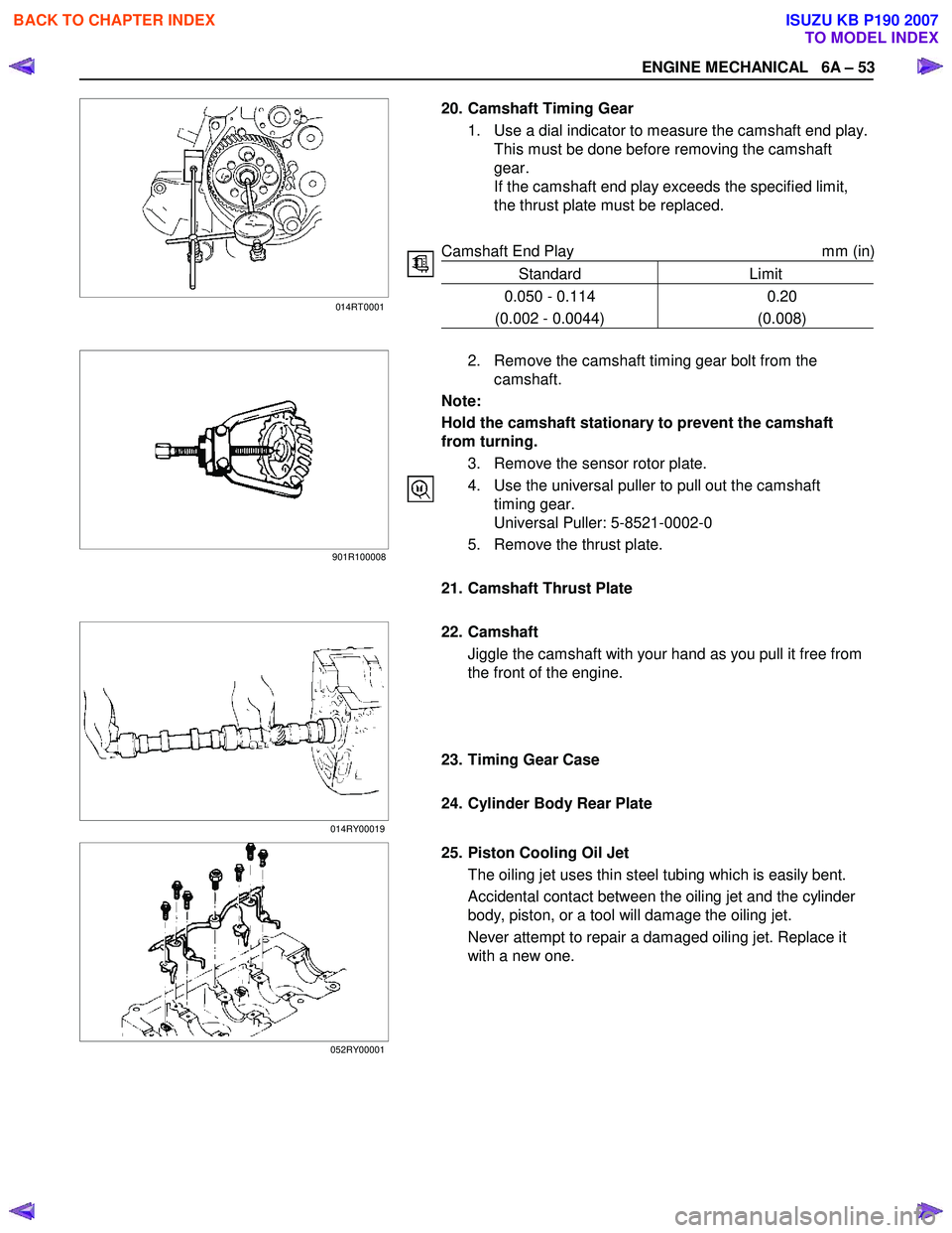
1. Use a dial indicator to measure the camshaft end play.This must be done before removing the camshaft
gear.
If the camshaft end play exceeds the specified limit,
the thrust plate must be replaced.
Camshaft End Play mm (in)
Standard Limit
0.050 - 0.114
(0.002 - 0.0044) 0.20
(0.008)
2. Remove the camshaft timing gear bolt from the
camshaft.
Note:
Hold the camshaft stationary to prevent the camshaft
from turning.
3. Remove the sensor rotor plate.
4. Use the universal puller to pull out the camshaft timing gear.
Universal Puller: 5-8521-0002-0
5. Remove the thrust plate.
21. Camshaft Thrust Plate
22. Camshaft
Jiggle the camshaft with your hand as you pull it free from
the front of the engine.
23. Timing Gear Case
24. Cylinder Body Rear Plate
25. Piston Cooling Oil Jet The oiling jet uses thin steel tubing which is easily bent.
Accidental contact between the oiling jet and the cylinder
body, piston, or a tool will damage the oiling jet.
Never attempt to repair a damaged oiling jet. Replace it
with a new one.
014RT0001
901R100008
014RY00019
052RY00001
BACK TO CHAPTER INDEX
TO MODEL INDEX
ISUZU KB P190 2007
Page 867 of 6020
6A – 62 ENGINE MECHANICAL
Manifold Fitting Face Warpage
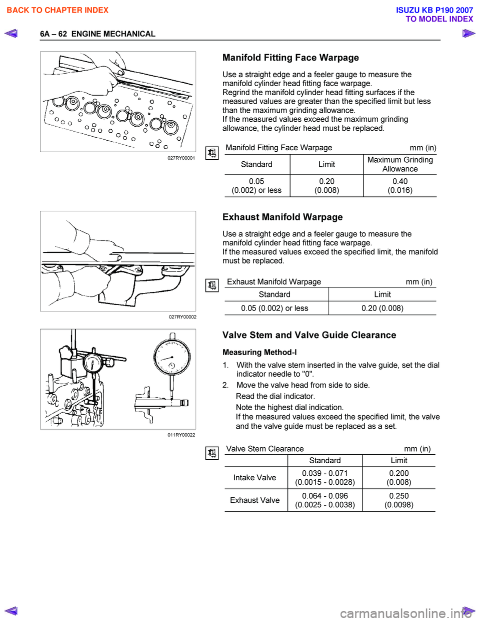
Use a straight edge and a feeler gauge to measure the
manifold cylinder head fitting face warpage.
Regrind the manifold cylinder head fitting surfaces if the
measured values are greater than the specified limit but less
than the maximum grinding allowance.
If the measured values exceed the maximum grinding
allowance, the cylinder head must be replaced.
Manifold Fitting Face Warpage mm (in)
Standard Limit Maximum Grinding
Allowance
0.05
(0.002) or less 0.20
(0.008) 0.40
(0.016)
Exhaust Manifold Warpage
Use a straight edge and a feeler gauge to measure the
manifold cylinder head fitting face warpage.
If the measured values exceed the specified limit, the manifold
must be replaced.
Exhaust Manifold Warpage mm (in)
Standard Limit
0.05 (0.002) or less 0.20 (0.008)
Valve Stem and Valve Guide Clearance
Measuring Method-I
1. With the valve stem inserted in the valve guide, set the dial indicator needle to "0".
2. Move the valve head from side to side. Read the dial indicator.
Note the highest dial indication.
If the measured values exceed the specified limit, the valve
and the valve guide must be replaced as a set.
Valve Stem Clearance mm (in)
Standard Limit
Intake Valve 0.039 - 0.071
(0.0015 - 0.0028) 0.200
(0.008)
Exhaust Valve 0.064 - 0.096
(0.0025 - 0.0038) 0.250
(0.0098)
027RY00001
027RY00002
011RY00022
BACK TO CHAPTER INDEX
TO MODEL INDEX
ISUZU KB P190 2007
Page 873 of 6020
6A – 68 ENGINE MECHANICAL
ROCKER ARM SHAFT AND ROCKER ARM
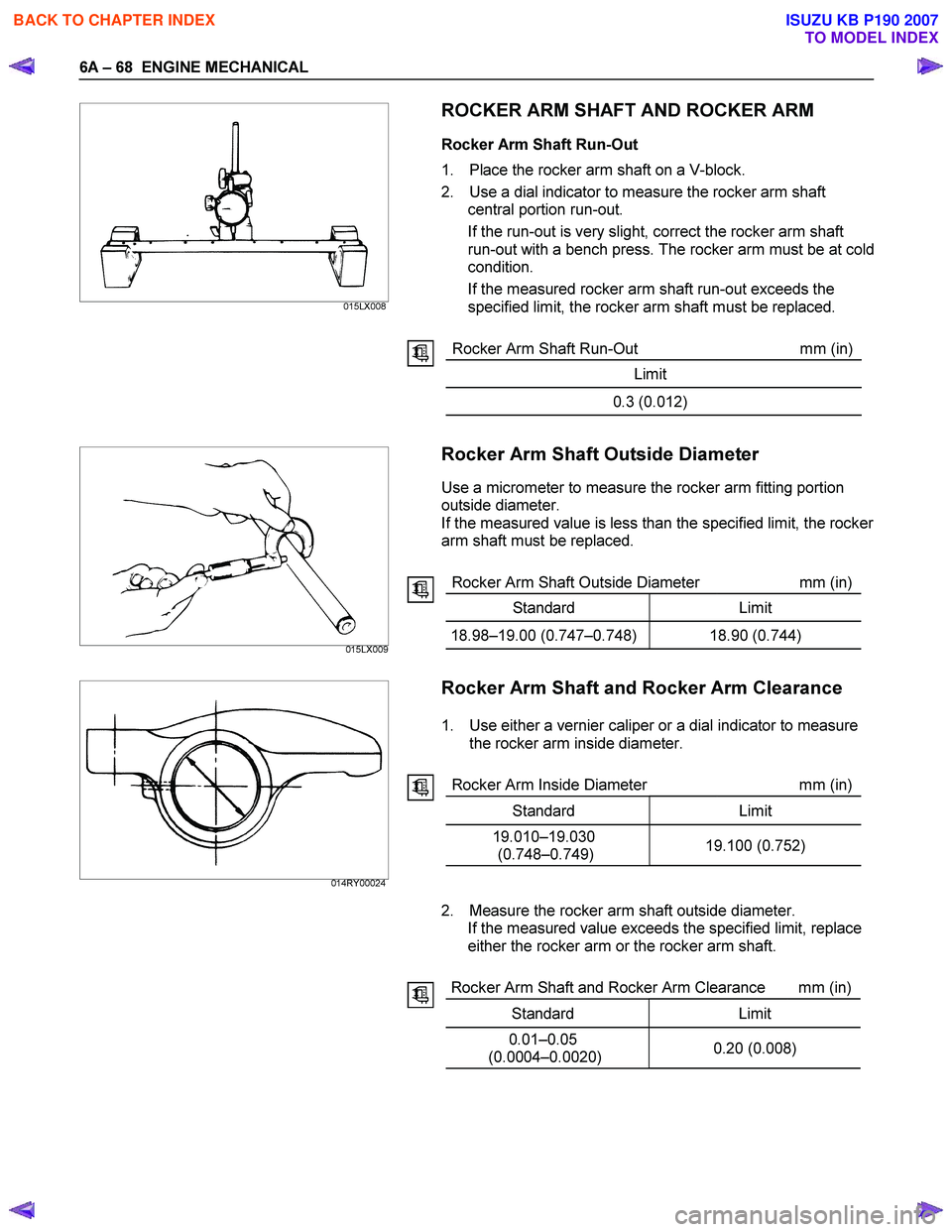
Rocker Arm Shaft Run-Out
1. Place the rocker arm shaft on a V-block.
2. Use a dial indicator to measure the rocker arm shaft central portion run-out.
If the run-out is very slight, correct the rocker arm shaft
run-out with a bench press. The rocker arm must be at cold
condition.
If the measured rocker arm shaft run-out exceeds the
specified limit, the rocker arm shaft must be replaced.
Rocker Arm Shaft Run-Out mm (in)
Limit
0.3 (0.012)
Rocker Arm Shaft Outside Diameter
Use a micrometer to measure the rocker arm fitting portion
outside diameter.
If the measured value is less than the specified limit, the rocker
arm shaft must be replaced.
Rocker Arm Shaft Outside Diameter mm (in)
Standard Limit
18.98–19.00 (0.747–0.748) 18.90 (0.744)
Rocker Arm Shaft and Rocker Arm Clearance
1. Use either a vernier caliper or a dial indicator to measure
the rocker arm inside diameter.
Rocker Arm Inside Diameter mm (in)
Standard Limit
19.010–19.030 (0.748–0.749) 19.100 (0.752)
2. Measure the rocker arm shaft outside diameter.
If the measured value exceeds the specified limit, replace
either the rocker arm or the rocker arm shaft.
Rocker Arm Shaft and Rocker Arm Clearance mm (in)
Standard Limit
0.01–0.05
(0.0004–0.0020) 0.20 (0.008)
015LX009
014RY00024 015LX008
BACK TO CHAPTER INDEX
TO MODEL INDEX
ISUZU KB P190 2007
Page 875 of 6020
6A – 70 ENGINE MECHANICAL
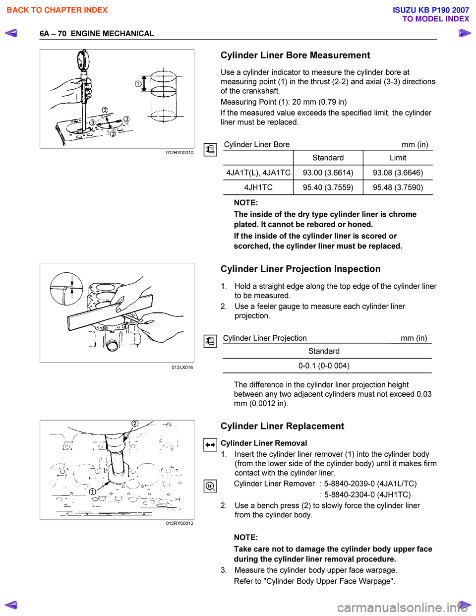
Cylinder Liner Bore Measurement
Use a cylinder indicator to measure the cylinder bore at
measuring point (1) in the thrust (2-2) and axial (3-3) directions
of the crankshaft.
Measuring Point (1): 20 mm (0.79 in)
If the measured value exceeds the specified limit, the cylinder
liner must be replaced.
Cylinder Liner Bore mm (in)
Standard Limit
4JA1T(L), 4JA1TC 93.00 (3.6614) 93.08 (3.6646)
4JH1TC 95.40 (3.7559) 95.48 (3.7590)
NOTE:
The inside of the dry type cylinder liner is chrome
plated. It cannot be rebored or honed.
If the inside of the cylinder liner is scored or
scorched, the cylinder liner must be replaced.
Cylinder Liner Projection Inspection
1. Hold a straight edge along the top edge of the cylinder liner
to be measured.
2. Use a feeler gauge to measure each cylinder liner projection.
Cylinder Liner Projection mm (in)
Standard
0-0.1 (0-0.004)
The difference in the cylinder liner projection height
between any two adjacent cylinders must not exceed 0.03
mm (0.0012 in).
Cylinder Liner Replacement
Cylinder Liner Removal
1. Insert the cylinder liner remover (1) into the cylinder body (from the lower side of the cylinder body) until it makes firm
contact with the cylinder liner.
Cylinder Liner Remover : 5-8840-2039-0 (4JA1L/TC)
: 5-8840-2304-0 (4JH1TC)
2. Use a bench press (2) to slowly force the cylinder liner from the cylinder body.
NOTE:
Take care not to damage the cylinder body upper face
during the cylinder liner removal procedure.
3. Measure the cylinder body upper face warpage. Refer to "Cylinder Body Upper Face Warpage".
012RY00010
012LX016
012RY00012
BACK TO CHAPTER INDEX
TO MODEL INDEX
ISUZU KB P190 2007
Page 882 of 6020
ENGINE MECHANICAL 6A – 77
CAMSHAFT
Visually inspect the journals, the cams, the oil pump drive gear,
and the camshaft bearings for excessive wear and damage.
The camshaft and the camshaft bearings must be replaced if
these conditions are discovered during inspection.
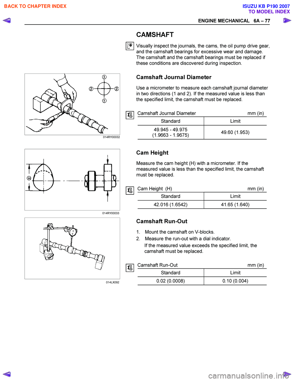
Camshaft Journal Diameter
Use a micrometer to measure each camshaft journal diameter
in two directions (1 and 2). If the measured value is less than
the specified limit, the camshaft must be replaced.
Camshaft Journal Diameter mm (in)
Standard Limit
49.945 - 49.975
(1.9663 - 1.9675) 49.60 (1.953)
Cam Height
Measure the cam height (H) with a micrometer. If the
measured value is less than the specified limit, the camshaft
must be replaced.
Cam Height (H) mm (in)
Standard Limit
42.016 (1.6542) 41.65 (1.640)
Camshaft Run-Out
1. Mount the camshaft on V-blocks.
2. Measure the run-out with a dial indicator. If the measured value exceeds the specified limit, the
camshaft must be replaced.
Camshaft Run-Out mm (in)
Standard Limit
0.02 (0.0008) 0.10 (0.004)
014RY00032
014RY00033 014LX092
BACK TO CHAPTER INDEX
TO MODEL INDEX
ISUZU KB P190 2007
Page 883 of 6020
6A – 78 ENGINE MECHANICAL
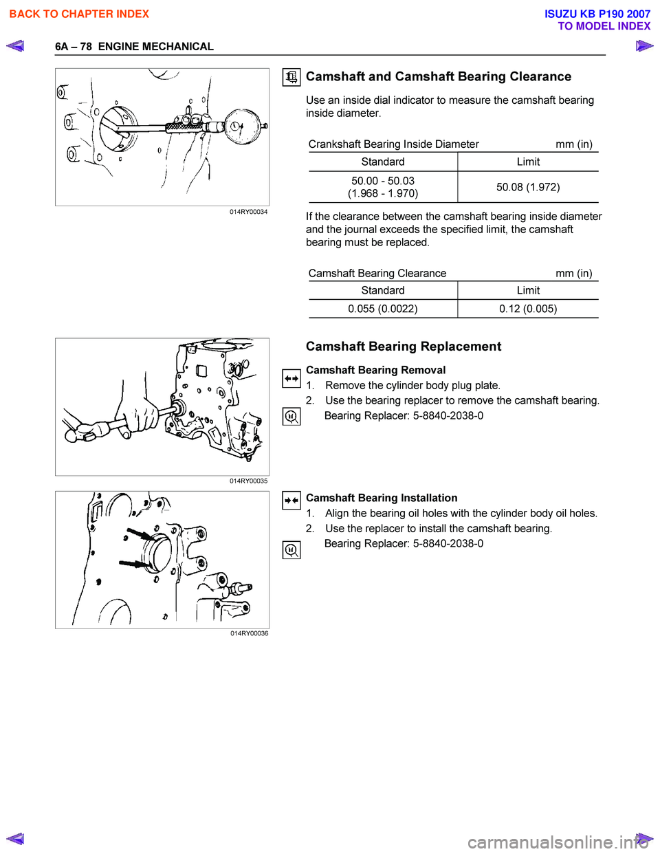
Camshaft and Camshaft Bearing Clearance
Use an inside dial indicator to measure the camshaft bearing
inside diameter.
Crankshaft Bearing Inside Diameter mm (in)
Standard Limit
50.00 - 50.03
(1.968 - 1.970) 50.08 (1.972)
If the clearance between the camshaft bearing inside diameter
and the journal exceeds the specified limit, the camshaft
bearing must be replaced.
Camshaft Bearing Clearance mm (in)
Standard Limit
0.055 (0.0022) 0.12 (0.005)
Camshaft Bearing Replacement
Camshaft Bearing Removal
1. Remove the cylinder body plug plate.
2. Use the bearing replacer to remove the camshaft bearing. Bearing Replacer: 5-8840-2038-0
Camshaft Bearing Installation
1. Align the bearing oil holes with the cylinder body oil holes.
2. Use the replacer to install the camshaft bearing. Bearing Replacer: 5-8840-2038-0
014RY00034
014RY00035 014RY00036
BACK TO CHAPTER INDEX
TO MODEL INDEX
ISUZU KB P190 2007
Page 884 of 6020
ENGINE MECHANICAL 6A – 79
CRANKSHAFT AND BEARING
Inspect the surface of the crankshaft journals and crankpins for
excessive wear and damage.
Inspect the oil seal fitting surfaces for excessive wear and
damage.
Inspect the oil ports for obstructions.
NOTE:
To increase crankshaft strength, tufftriding (Nitrizing
Treatment) has been applied. Because of this, it is not
possible to regrind the crankshaft surfaces.
Therefore, under size bearing are not available.
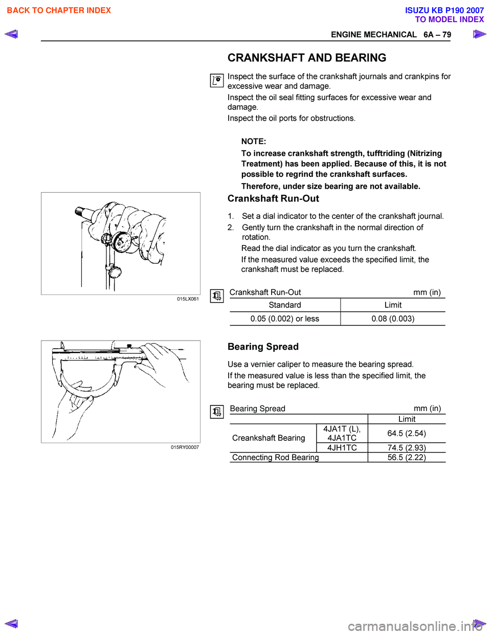
Crankshaft Run-Out
1. Set a dial indicator to the center of the crankshaft journal.
2. Gently turn the crankshaft in the normal direction of rotation.
Read the dial indicator as you turn the crankshaft.
If the measured value exceeds the specified limit, the
crankshaft must be replaced.
Crankshaft Run-Out mm (in)
Standard Limit
0.05 (0.002) or less 0.08 (0.003)
Bearing Spread
Use a vernier caliper to measure the bearing spread.
If the measured value is less than the specified limit, the
bearing must be replaced.
Bearing Spread mm
(in)
Limit
4JA1T (L), 4JA1TC 64.5 (2.54)
Creankshaft Bearing
4JH1TC 74.5 (2.93)
Connecting Rod Bearing 56.5 (2.22)
015LX061
015RY00007
BACK TO CHAPTER INDEX
TO MODEL INDEX
ISUZU KB P190 2007
Page 886 of 6020
ENGINE MECHANICAL 6A – 81
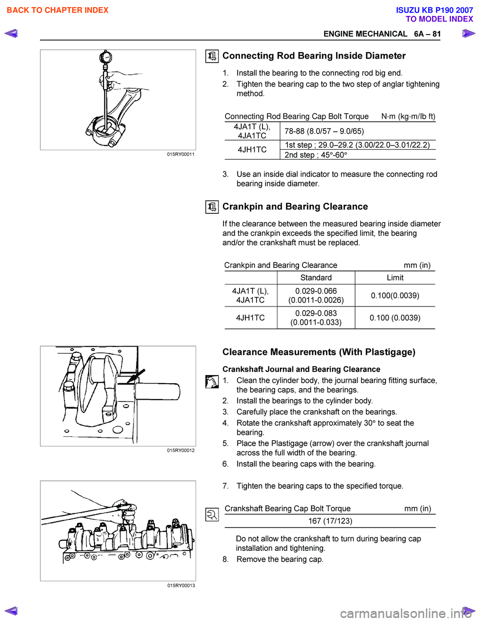
Connecting Rod Bearing Inside Diameter
1. Install the bearing to the connecting rod big end.
2. Tighten the bearing cap to the two step of anglar tightening method.
Connecting Rod Bearing Cap Bolt Torque
N·m (kg·m/Ib ft)
4JA1T (L), 4JA1TC 78-88 (8.0/57 – 9.0/65)
1st step ; 29.0–29.2 (3.00/22.0–3.01/22.2)4JH1TC
2nd step ; 45°-60 °
3. Use an inside dial indicator to measure the connecting rod
bearing inside diameter.
Crankpin and Bearing Clearance
If the clearance between the measured bearing inside diameter
and the crankpin exceeds the specified limit, the bearing
and/or the crankshaft must be replaced.
Crankpin and Bearing Clearance mm (in)
Standard Limit
4JA1T (L),
4JA1TC 0.029-0.066
(0.0011-0.0026) 0.100(0.0039)
4JH1TC
0.029-0.083
(0.0011-0.033) 0.100 (0.0039)
Clearance Measurements (With Plastigage)
Crankshaft Journal and Bearing Clearance
1. Clean the cylinder body, the journal bearing fitting surface, the bearing caps, and the bearings.
2. Install the bearings to the cylinder body.
3. Carefully place the crankshaft on the bearings.
4. Rotate the crankshaft approximately 30 ° to seat the
bearing.
5. Place the Plastigage (arrow) over the crankshaft journal across the full width of the bearing.
6. Install the bearing caps with the bearing.
7. Tighten the bearing caps to the specified torque.
Crankshaft Bearing Cap Bolt Torque mm (in)
167 (17/123)
Do not allow the crankshaft to turn during bearing cap
installation and tightening.
8. Remove the bearing cap.
015RY00012
015RY00013
015RY00011
BACK TO CHAPTER INDEX
TO MODEL INDEX
ISUZU KB P190 2007