engine coolant ISUZU KB P190 2007 Workshop Manual Online
[x] Cancel search | Manufacturer: ISUZU, Model Year: 2007, Model line: KB P190, Model: ISUZU KB P190 2007Pages: 6020, PDF Size: 70.23 MB
Page 1314 of 6020

6E-280 Engine Control System (4JH1)
EGR Solenid Valve Replacement
Removal Procedure 1. Disconenct the negative battery cable.
2. Disconnect a EGR solenoid valve harness connector.
3. Disconnect two hoses from the EGR solenoid valve.
4. Loosen two bolts and remove the EGR solenoid valve from the bracket.
Installation Procedure
1. Tighten the purge solenoid by tow bolts.
2. Connect a connector to the EGR solenoid valve.
3. Connect two hoses to the EGR solenoid valve.
4. Connect the negative battery cable.
Engine Coolant Temperature (ECT) Sensor
Replacement
1. Removal Procedure
2. Disconnect the negative battery cable.
3. Drain enough engine coolant so that the coolant level will be below the ECT sensor.
4. Disconnect connector from the ECT sensor.
5. Loosen and remove the ECT sensor from the thermostat housing.
Notice: Cool down the engine before above procedures
are carried out.
Installation Procedure
1.
Apply sealer to threads of screw at the ECT
sensor.
2. Tighten the ECT sensor with specified tightening torque.
Tightening Torque • Bolt: 13 N.m (1.3 kgf.m)
3. Connect a ECT sensor connector to the ECT sensor.
4. Fill the engine coolant.
5. Connect the negative battery cable.
Notice: Verify no engine coolant leaking from the
sensor threads after replacement.
Mass Air Flow (MAF) / Intake Air
Temperature (IAT) Sensor Replacement
Removal Procedure
1. Disconnect the negative battery cable.
2. Disconnect a MAF & IAT sensor connector from the MAF & IAT sensor assembly.
3. Loosen the clips and remove the MAF & IAT sensor assembly from the intake duct housing.
BACK TO CHAPTER INDEX
TO MODEL INDEX
ISUZU KB P190 2007
Page 1319 of 6020

Engine Control System (4JH1) 6E-285
Crankshaft Position (CKP) Sensor
RTW 06ESH000101
RTW 66ESH001401
Legend
1. Crankshaft Position (CKP) Sensor
2. Flywheel
3. Slit
The crankshaft position (CKP) sensor is located on top
of the flywheel housing. There are 4 slits spaced 90 °
on the flywheel circumference. The CKP sensor is a
magnetic coil type sensor , which generates an AC
signal voltage based on the crankshaft rotational speed.
The ECM monitors both the CKP sensor and injection
pump camshaft position (CMP) sensor signals to
ensure they correlate with each other.
The following waveform aids to diagnose when there is
an oscilloscope or equivalent.
Engine Coolant Temperature (ECT) Sensor
- Amplitudes of CKP sensor signal (CH1) increase as engine speed increases.
- Each waveform cycle shorten as the engine speed increases.
Terminal: 90 (CH1), 91 (CH2) (+) / GND (-)
Scale: 10V/div 2ms/div
Condition: Approximately 1000RPM
CH1
0V
CH2 0V
RTW 66ESH001501
Legend
1. Engine Coolant Temperature (ECT) Sensor
The engine coolant temperature (ECT) sensor is
installed to the thermostat housing. The ECT sensor is
a variable resistor. The ECT sensor measures the
temperature of the engine coolant. The engine control
module (ECM) supplies 5 volts to the ECT signal circuit
and a ground for the ECT low reference circuit. W hen
the ECT sensor is cold, the sensor resistance is high.
W hen the engine coolant temperature increases, the
sensor resistance decreases. W ith high senso
r
resistance, the ECM detects a high voltage on the ECT
signal circuit. W ith lower sensor resistance, the ECM
detects a lower voltage on the ECT signal circuit.
BACK TO CHAPTER INDEX
TO MODEL INDEX
ISUZU KB P190 2007
Page 1320 of 6020

6E-286 Engine Control System (4JH1)
Exhaust Gas Recirculation (EGR) Solenoid Valve
RTW 76ESH003601
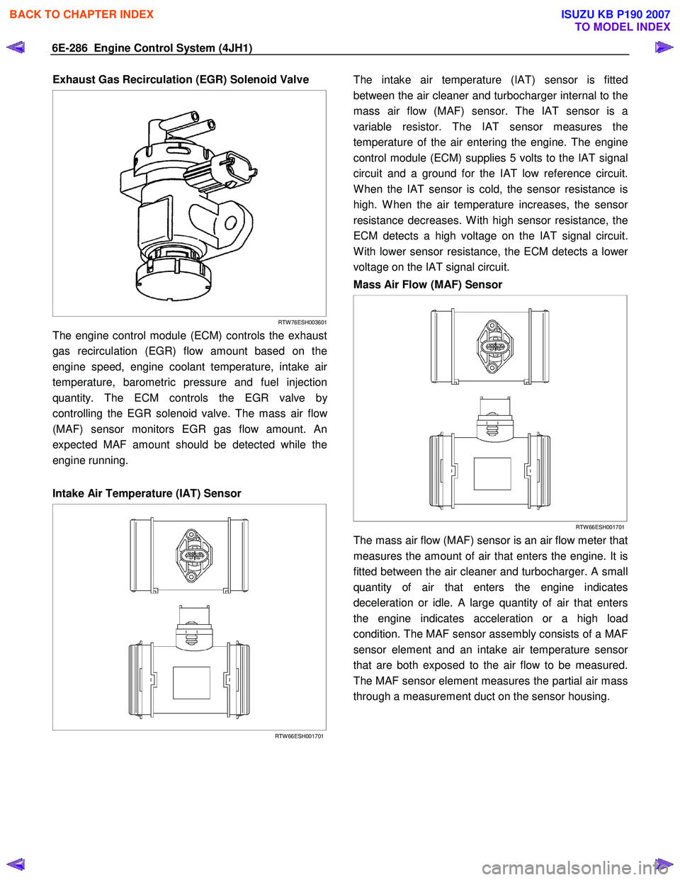
The engine control module (ECM) controls the exhaust
gas recirculation (EGR) flow amount based on the
engine speed, engine coolant temperature, intake ai
r
temperature, barometric pressure and fuel injection
quantity. The ECM controls the EGR valve b
y
controlling the EGR solenoid valve. The mass air flo
w
(MAF) sensor monitors EGR gas flow amount. An
expected MAF amount should be detected while the
engine running.
Intake Air Temperature (IAT) Sensor
RTW 66ESH001701
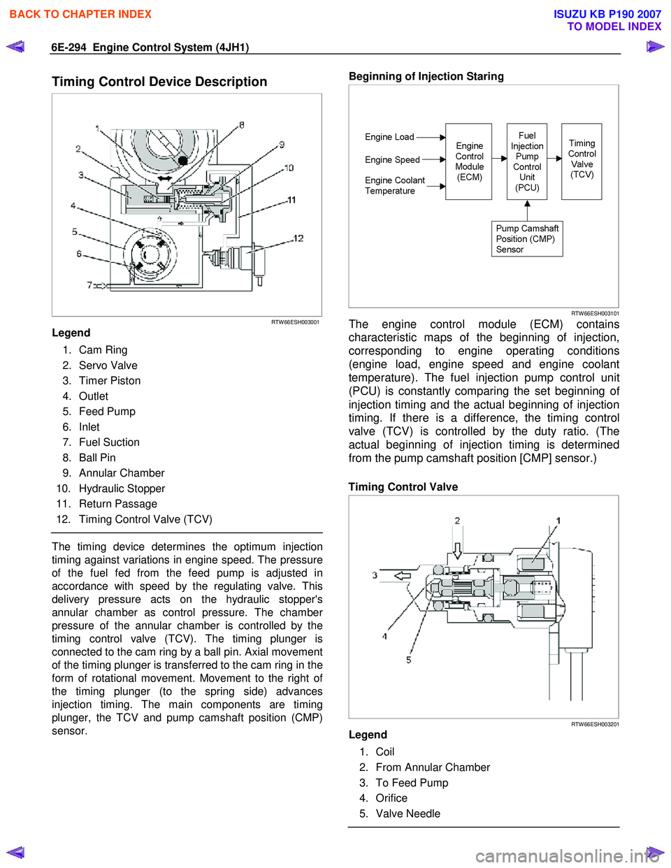
The intake air temperature (IAT) sensor is fitted
between the air cleaner and turbocharger internal to the
mass air flow (MAF) sensor. The IAT sensor is a
variable resistor. The IAT sensor measures the
temperature of the air entering the engine. The engine
control module (ECM) supplies 5 volts to the IAT signal
circuit and a ground for the IAT low reference circuit.
W hen the IAT sensor is cold, the sensor resistance is
high. W hen the air temperature increases, the senso
r
resistance decreases. W ith high sensor resistance, the
ECM detects a high voltage on the IAT signal circuit.
W ith lower sensor resistance, the ECM detects a lowe
r
voltage on the IAT signal circuit.
Mass Air Flow (MAF) Sensor
RTW 66ESH001701
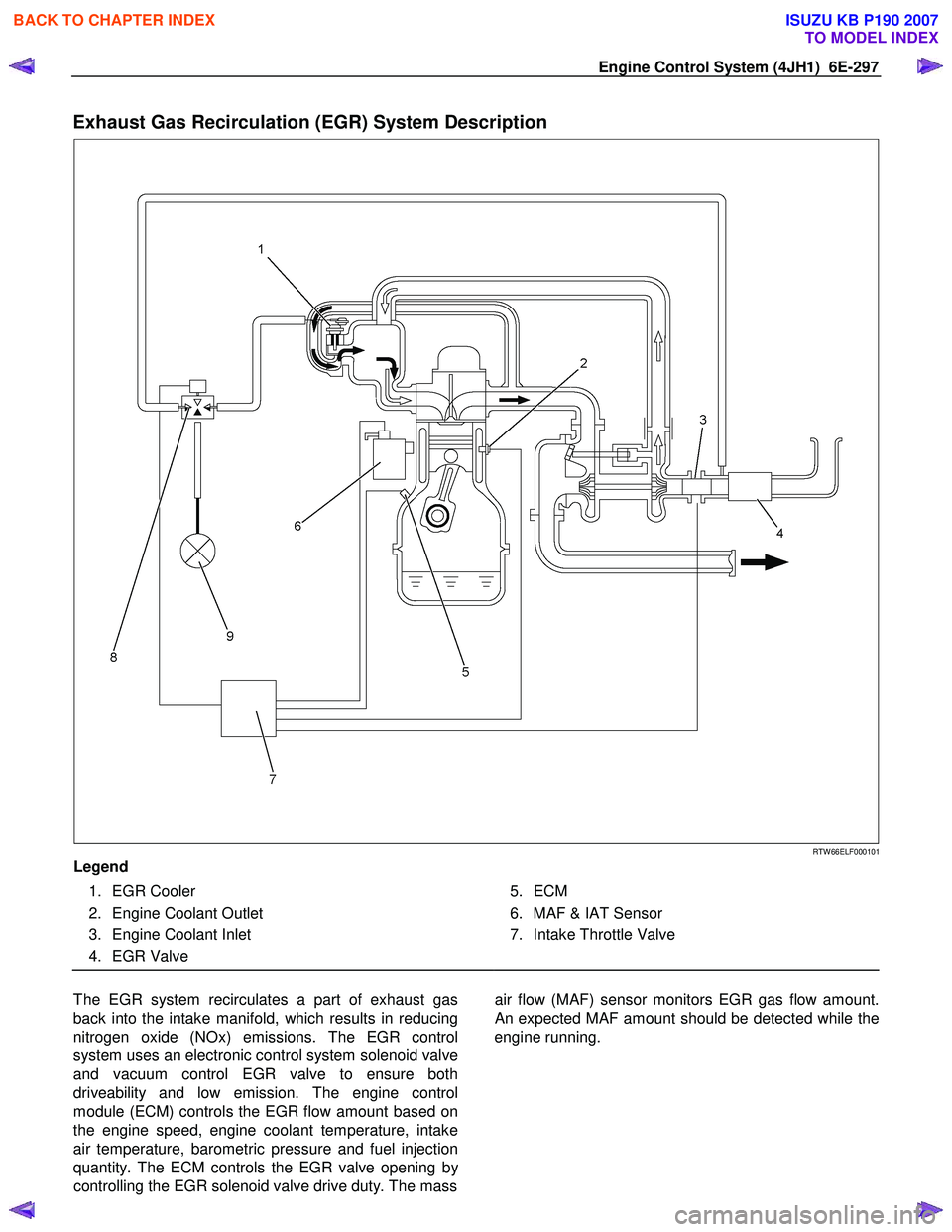
The mass air flow (MAF) sensor is an air flow meter that
measures the amount of air that enters the engine. It is
fitted between the air cleaner and turbocharger. A small
quantity of air that enters the engine indicates
deceleration or idle. A large quantity of air that enters
the engine indicates acceleration or a high load
condition. The MAF sensor assembly consists of a MAF
sensor element and an intake air temperature senso
r
that are both exposed to the air flow to be measured.
The MAF sensor element measures the partial air mass
through a measurement duct on the sensor housing.
BACK TO CHAPTER INDEX
TO MODEL INDEX
ISUZU KB P190 2007
Page 1328 of 6020

6E-294 Engine Control System (4JH1)
Timing Control Device Description
RTW 66ESH003001
Legend
1. Cam Ring
2. Servo Valve
3. Timer Piston
4. Outlet
5. Feed Pump
6. Inlet
7. Fuel Suction
8. Ball Pin
9. Annular Chamber
10. Hydraulic Stopper
11. Return Passage
12. Timing Control Valve (TCV)
The timing device determines the optimum injection
timing against variations in engine speed. The pressure
of the fuel fed from the feed pump is adjusted in
accordance with speed by the regulating valve. This
delivery pressure acts on the hydraulic stopper's
annular chamber as control pressure. The chambe
r
pressure of the annular chamber is controlled by the
timing control valve (TCV). The timing plunger is
connected to the cam ring by a ball pin. Axial movement
of the timing plunger is transferred to the cam ring in the
form of rotational movement. Movement to the right o
f
the timing plunger (to the spring side) advances
injection timing. The main components are timing
plunger, the TCV and pump camshaft position (CMP)
sensor.
Beginning of Injection Staring
RTW 66ESH003101
The engine control module (ECM) contains
characteristic maps of the beginning of injection,
corresponding to engine operating conditions
(engine load, engine speed and engine coolant
temperature). The fuel injection pump control unit
(PCU) is constantly comparing the set beginning o
f
injection timing and the actual beginning of injection
timing. If there is a difference, the timing control
valve (TCV) is controlled by the duty ratio. (The
actual beginning of injection timing is determined
from the pump camshaft position [CMP] sensor.)
Timing Control Valve
RTW 66ESH003201
Legend
1. Coil
2. From Annular Chamber
3. To Feed Pump
4. Orifice
5. Valve Needle
BACK TO CHAPTER INDEX
TO MODEL INDEX
ISUZU KB P190 2007
Page 1331 of 6020

Engine Control System (4JH1) 6E-297
Exhaust Gas Recirculation (EGR) System Description
RTW 66ELF000101
Legend
1. EGR Cooler
2. Engine Coolant Outlet
3. Engine Coolant Inlet
4. EGR Valve
5. ECM
6. MAF & IAT Sensor
7. Intake Throttle Valve
The EGR system recirculates a part of exhaust gas
back into the intake manifold, which results in reducing
nitrogen oxide (NOx) emissions. The EGR control
system uses an electronic control system solenoid valve
and vacuum control EGR valve to ensure both
driveability and low emission. The engine control
module (ECM) controls the EGR flow amount based on
the engine speed, engine coolant temperature, intake
air temperature, barometric pressure and fuel injection
quantity. The ECM controls the EGR valve opening b
y
controlling the EGR solenoid valve drive duty. The mass
air flow (MAF) sensor monitors EGR gas flow amount.
An expected MAF amount should be detected while the
engine running.
BACK TO CHAPTER INDEX
TO MODEL INDEX
ISUZU KB P190 2007
Page 1365 of 6020

ENGINE MECHANICAL (4JK1/4JJ1) 6A-5
EGR system
Based upon data, including water temperature, engine
speeds or engine loads, it is controlled via Engine
Control Module (ECM) to purify exhaust by recycling
part of it.
Its main components include an EGR valve, an EGR
cooler and various sensors.
Connecting rod cap bolt
The angular tightening method of the connecting rod
cap bolt further increases reliability and durability.
Fuel rail-type electronic control injection system
The fuel rail-type electronic control injection system is
composed of a fuel supply pump that sets the target
pressure of high-pressure fuel and supply it, a fuel rail
that measures such high-pressure fuel and a fuel
injector that turns it into a fine spray and injects it. Each
is controlled via ECM based upon various signals, while
injection timing or fuel injection quantity is controlled
under every possible driving condition.
Fuel injector
The fuel injector is a 6-hole nozzle that adjusts fuel
injection quantity or injection timing by opening o
r
closing an electromagnetic valve on the head of the fuel
injector.
ECM corrects the dispersion of fuel injection quantit
y
between fuel injector according to ID code data in
memory. At the replacement of fuel injector, ID code
data should be stored in ECM.
Fuel filter with sedimenter
It is a fuel filter with sedimenter that gets rid of water by
making use of the difference in specific gravity between
light oil and water, which comes with an indicator that
notifies you that it is filled with water.
Preheating system
The preheating system consists of the ECM, the glow
relay, glow plugs and the glow indicator lamp. The
preheating system is operated when the engine coolant
temperature is low, and makes the engine easy to start.
Lubrication system
It is an oil filter with full-flow bypass, which uses a
water-cool oil cooler and oil jet to cool the piston.
Functional inspection
Inspection/adjustment of valve clearance 1. Inspection of valve clearance
• Remove the fuel injector harness assembly.
• Remove the leak off hose.
• Remove the cylinder head cover.
• Rotate the crankshaft to make the No.1
cylinder meet the compression top dead cente
r
(TDC).
RTW 76ASH001301
Legend
1. TDC
BACK TO CHAPTER INDEX
TO MODEL INDEX
ISUZU KB P190 2007
Page 1373 of 6020

ENGINE MECHANICAL (4JK1/4JJ1) 6A-13
Main Data and specifications
Item Engine model 4JK1 Engine model 4JJ1
Type Diesel/4-cycle/water cooling-type in-line DOHC
Combustion chamber type Direct injection type
Cylinder liner type Liner less
Number of cylinders -cylinder
bore × strokes mm (in) 4-95.4 (3.76) × 87.4 (3.44) 4-95.4(3.76) × 104.9(4.13)
Displacement
cc (cu.in) 2499 (152) 2999 (183)
Compression ratio 18.3 17.5
Compression pressure MPa (psi)/rpm 3 (435)/200
Idling speed rpm 700 ± 25
Valve clearance Intake 0.15 (0.006) (cold)
mm (in) Exhaust 0.15 (0.006) (cold)
Ignition type Compressed ignition
Injection order 1 - 3 - 4 - 2
Lubricating system
Lubricating type Pressure delivery type
Oil pump type Gear type
Volume of lubricating oil L (qts) 8.0 (8.5)
Oil filter type Full flow filter (cartridge type)
Oil cooling type Built-in-type, water cooling
Cooling system
Cooling type W ater cooling type
Radiator type Corrugated fin (pressure type)
W ater pump type Centrifugal, belt drive type
Thermostat type W ax-type units
Thermostat valve-opening temperature °C ( °F) 85 (185)
Volume of coolant L (qts) M/T8.7 (9.2) A/T 8.6 (9.1) (incl. radiator)
Fuel system
Injection pump type Fuel supply pump fuel rail type
Fuel injector type Electronic control injector
6-hole
Fuel pump type Into the fuel tank type
Charging system
Generator type AC type
Power output V-A 12 - 90
BACK TO CHAPTER INDEX
TO MODEL INDEX
ISUZU KB P190 2007
Page 1375 of 6020

ENGINE MECHANICAL (4JK1/4JJ1) 6A-15
Engine Assembly
Removal
1. Disconnect the negative battery cable.
2. Remove the engine hood.
3. Drain the coolant.
4. Remove the starter motor.
5. Remove the transmission assembly.
Refer to removal procedure for “TRANSMISSION” in this manual.
6. Disconnect the ECM harness connector.
7. Remove the ECM.
8. Remove the air cleaner. • Disconnect the MAF sensor harness connector.
• Remove the intake pipe with the lid of ai
r
cleaner box.
• Remove the air cleaner box.
RTW 76ASH000401
Legend
1. ECM Harness Connector
2. ECM
3. Air Cleaner Box
4. MAF Sensor Harness Connector
9. Remove the intake hose (intercooler - intake
throttle) (Standard output).
10. Remove the intake hose (turbocharger - intercooler) (Standard output).
Remove the harness connector.
RTW 56ASH004001
Legend
1. Intake Hose (intercooler - intake throttle)
2. Intake Hose (turbocharger - intercooler)
11. Remove the intercooler (High output).
• Disconnect the BARO sensor harness
connector (2).
• Remove the two intake hoses.
• Remove the intercooler (1).
RTW 76ASH000501
12. Remove the radiator upper hose.
13. Remove the engine harness clip (1).
BACK TO CHAPTER INDEX
TO MODEL INDEX
ISUZU KB P190 2007
Page 1378 of 6020

6A-18 ENGINE MECHANICAL (4JK1/4JJ1)
21.Install the intake hose (intercooler - intake throttle)
(Standard output).
RTW 56ASH004001
22.Install the intercooler (High output).
• Install the intercooler.
• Install the two intake hoses.
• Connect the BARO sensor harness connector.
23.Install the air cleaner.
• Install the intake pipe with the lid of air cleane
r
box.
• Install the air cleaner box.
• Connect the MAF sensor harness connector.
24.Install the ECM.
25.Connect the ECM harness connector.
26.Install the transmission assembly.
Refer to installation procedure fo
r
“TRANSMISSION”.
27.Install the starter motor.
Tightening torque: 94 N ⋅
⋅⋅
⋅
m (9.6kg ⋅
⋅⋅
⋅
m / 69 lb ft)
28.Replenish the coolant.
29.Install the engine hood.
Tightening torque: 10 N ⋅
⋅⋅
⋅
m (1.0kg ⋅
⋅⋅
⋅
m / 87 lb in)
30.Connect the negative battery cable.
BACK TO CHAPTER INDEX
TO MODEL INDEX
ISUZU KB P190 2007
Page 1394 of 6020

6A-34 ENGINE MECHANICAL (4JK1/4JJ1)
Removal
1. Loosen the radiator drain plug to drain coolant.
2. Remove the engine cover.
3. Remove the intake hose from the intercooler and intake throttle.
4. Remove the intake hose from the turbocharge
r
and the intercooler.
5. Remove the air intake duct from the turbocharge
r
and the air cleaner.
6. Remove the EGR cooler.
Refer to “EGR Cooler” in EXHAUST SYSTEM Section.
7. Remove the oil feed pipe.
8. Remove the oil return pipe. • Loosen clamp (1) of A/T oil cooler pipe.
RTW 56ASH025101
9. Remove the water feed and return pipe.
RTW 56ASH005401
Legend
1. Oil Feed Pipe
2. EGR Cooler
3. W ater Feed Pipe
4. W ater Return Pipe
5. Oil Return Pipe
10. Remove the front exhaust pipe.
RTW 56ASH018301
Legend
1. Gasket
2. Front Exhaust Pipe (4 ×2 High Ride Suspention,
4 ×4)
3. Gasket
4. Front Exhaust Pipe (4 ×2 Except High Ride
Suspention)
11. Disconnect the front propeller shaft flange (1)
(Front Diff Side, 4 ×4 only).
RTW 76ASH002301
BACK TO CHAPTER INDEX
TO MODEL INDEX
ISUZU KB P190 2007