diagram ISUZU TROOPER 1995 User Guide
[x] Cancel search | Manufacturer: ISUZU, Model Year: 1995, Model line: TROOPER, Model: ISUZU TROOPER 1995Pages: 1928
Page 698 of 1928
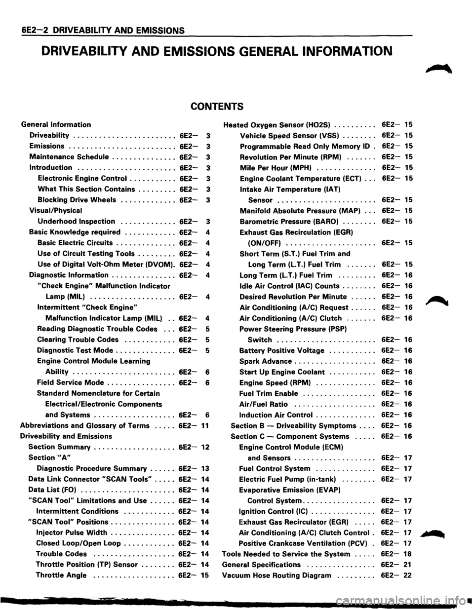
6E2-2 DRIVEABILITY AND EMISSIONS
DRIVEABILITV AND EMISSIONS GENERAL INFORMATION
CONTENTS
General Information
Driveability ....................... .
Emissions
........................ .
Maintenance
Schedule .............. .
Introduction ...................... .
Electronic Engine
Control .......... .
What This Section Contains ........ .
Blocking Drive Wheels
Visual/Physical
Underhood Inspection
6E2-3
6E2-3
6E2-3
6E2-3
6E2-3
6E2-3
6E2-3
6E2-3
Basic
Knowledge required . . . . . . . . . . . . 6E2-4
Basic Electric Circuits . . . . . . . . . . . . . .
6E2-4
Use
of Circuit Testing Tools . . . . . . . . . 6E2-4
Use
of Digital Volt-Ohm Meter (DVOM). 6E2-4
Diagnostic
Information . . . . . . . . . . . . . . . 6E2-4
"Check Engine" Malfunction Indicator
Lamp (MIL) . . . . . . . . . . . . . . . . . . . . 6E2-4
Intermittent "Check Engine"
Malfunction Indicator Lamp (MIL) . . 6E2-4
Reading Diagnostic
Trouble Codes . . . 6E2-5
Clearing
Trouble Codes . . . . . . . . . . . . 6E2-5
Diagnostic Test
Mode .............. 6E2-5
Engine Control
Module Learning
Ability . . . . . . . . . . . . . . . . . . . . . . . . 6E2-6
Field
Service Mode . . . . . . . . . . . . . . . . 6E2-6
Standard Nomenclature
for Certain
Electrical/Electronic
Components
and Systems . . . . . . . . . . . . . . . . . . . 6E2-6
Abbreviations and Glossary of Terms ..... 6E2-11
Driveability and Emissions
Section Summary ................... 6E2-12
Section .,. A"
Diagnostic Procedure Summary ...... 6E2-13
Data Link Connector
"SCAN Tools" ..... 6E2-14
Data
List (FO) ...................... 6E2-14
"SCAN Tool" Limitations and Use ...... 6E2-14
Intermittent Conditions ............ 6E2-14
"SCAN Tool" Positions ............... 6E2-14
Injector Pulse Width ............... 6E2-14
Closed Loop/Open Loop . . . . . . . . . . . .
6E2-14
Trouble Codes ................... 6E2-14
Throttle Position (TP) Sensor . . . . . . . . 6E2-14
Throttle Angle . . . . . . . . . . . . . . . . . . . 6E2-15 Heated
Oxygen
Sensor (H02S)
Vehicle Speed Sensor (VSS) ....... .
Programmable Read Only Memory ID .
Revolution
Per Minute (RPM) ...... .
Mile Per Hour (MPH) ............. .
Engine
Coolant Temperature (ECT) .. .
Intake Air Temperature (IAT)
Sensor
...................... .
Manifold Absolute Pressure (MAP) .. .
Barometric Pressure (BARO) ....... .
Exhaust Gas Recirculation
(EGR)
(ON/OFF) .................... .
Short Term (S.T.) Fuel Trim and
Long Term
(LT.) Fuel Trim ...... .
Long Term
(LT.) Fuel Trim ........ .
Idle Air Control (lAC) Counts ....... .
Desired Revolution
Per Minute ..... .
Air Conditioning (A/C) Request ..... .
Air Conditioning (A/C) Clutch ...... .
Power Steering Pressure (PSP)
Switch ...................... .
Battery Positive Voltage .......... .
Spark Advance .................. .
Start Up Engine Coolant .......... .
Engine
Speed (RPM) ............. .
Fuel Trim Enable ................ .
Air/Fuel Ratio .................. .
Induction Air Control ............. .
Section B -Driveability Symptoms ... .
Section C -Component Systems .... .
Engine
Control Module (ECM)
and
Sensors .................. .
Fuel Control System ............. .
Electric
Fuel Pump (in-tank) ....... .
Evaporative Emission
(EVAP)
Control System ................ .
Ignition Control (IC) .............. .
Exhaust Gas Recirculator
(EGR) .... .
Air Conditioning (A/C) Clutch Control .
Positive Crankcase Ventilation (PCV) .
Tools Needed
to Service the System .... .
General Specifications
............... .
Vacuum Hose Routing Diagram
........ .
6E2-15
6E2-15
6E2-15
6E2-15
6E2-15
6E2-15
6E2-15
6E2-15
6E2-15
6E2-15
6E2-15
6E2-16
6E2-16
6E2-16
6E2-16
6E2-16
6E2-16
6E2-16
6E2-16
6E2-16
6E2-16
6E2-16
6E2-16
6E2-16
6E2-16
6E2-16
6E2-17
6E2-17
6E2-17
6E2-17
6E2-17
6E2-17
6E2-17
6E2-17
6E2-18
6E2-21
6E2-22
~
... ...
•
Page 699 of 1928
---
DRIVEABILITV AND EMISSIONS 6E2-3
ALL NEW ISUZU VEHICLES ARE CERTIFIED BY THE UNITED STATES ENVIRONMENTAL PROTECTION
AGENCY AS CONFORMING TO THE REQUIREMENTS OF THE REGULATIONS FOR THE CONTROL OF AIR
POLLUTION FROM NEW MOTOR VEHICLES. THIS CERTIFICATION IS CONTINGENT ON CERTAIN
ADJUSTMENTS BEING SET TO FACTORY STANDARDS. IN MOST CASES, THESE ADJUSTMENT POINTS
EITHER HAVE BEEN PERMANENTLY SEALED AND/OR MADE INACCESSIBLE TO PREVENT INDISCRIMINATE
OR ROUTINE ADJUSTMENT IN THE FIELD. FOR THIS REASON, THE FACTORY PROCEDURE FOR
TEMPORARILY REMOVING PLUGS, CAPS, ETC., FOR PURPOSES OF SERVICING THE PRODUCT, MUST BE
STRICTLY FOLLOWED AND, WHEREVER PRACTICABLE, RETURNED TO THE ORIGINAL INTENT OF THE
DESIGN.
GENERAL INFORMATION
DRIVEABILITY
The driveability diagnosis procedures apply to various
systems in current
ISUZU vehicles. The procedures
assume
that the vehicle is worked on properly at one
time and the
problem is due to time, wear, dirt or other
causes.
Start with the introduction that follows. This
will describe a systematic diagnostic procedure.
Any system disconnected during diagnosis should be
reconnected. This
includes wires, hoses, linkage, etc.
EMISSIONS
The exhaust emission control systems used on
ISUZU engines perform a specific function to lower
exhaust emissions while maintaining good fuel
economy and driveability.
MAINTENANCE SCHEDULE
Refer to the Maintenance Schedule in Section "OB"
General Information for the maintenance service that
should be performed to retain emission control
performance.
INTRODUCTION
ELECTRONIC ENGINE CONTROL
All engines have an Engine Control Module (ECM)
to control the fuel system. The ECM varies the air/
fuel ratio by controlling the fuel flow through the
injectors.
In addition, the ECM controls the ignition timing,
fuel pump, and various other systems.
It is important to review the component sections
and
wiring diagrams in this Section for specific
components
controlled by the ECM and what
systems are non-ECM controlled.
WHAT THIS SECTION CONTAINS
Each ISUZU engine has system controls to reduce
exhaust emissions
while maintaining good
driveability and fuel economy. •
This Section explains:
•
How to use the Driveability and Emission
Section
"6E2" engines.
• A brief description of systems used to
control fuel and emissions.
• Abbreviations that are used in Driveability
and Emissions.
• Special tools used to diagnosis and repair a
system.
Before checking the
system, adhere to the
following information:
BLOCKING DRIVE WHEELS
The vehicle drive wheels should always be
blocked, and parking brake firmly set, while
checking the system.
VISUAL/PHYSICAL UNDERHOOD
INSPECTION
A careful visual and physical underhood
inspection must
be performed as part of any
diagnostic procedure
or in finding the cause of an
emissions test failure. This can often lead to fixing
a
problem without further steps. Inspect all
vacuum hoses for correct routing, pinches, cuts,
or disconnections. Be sure to inspect hoses that
are
difficult to see beneath the throttle body and
common chamber.
Inspect all the wires in the
engine
compartment for correct and good
connections, burned or chaffed spots, pinched
wires, or contact with sharp edges or hot exhaust
manifolds. This visual/physical inspection is very
important. It must be done carefully and
thoroughly.
Page 700 of 1928
6E2-4 DRIVEABILITY AND EMISSIONS
BASIC KNOWLEDGE REQUIRED
Before using this section of the Service Manual,
there are some areas that you should be familiar
with. Without this basic knowledge, you will have
trouble using the diagnostic procedures
contained in this section.
BASIC ELECTRIC CIRCUITS
You should understand the basic theory of
electricity, and know the meaning of voltage,
amps, and ohms. You should understand what
happens in a circuit with an open or a shorted
wire. You
should be able to read and understand a
wiring diagram. A shortto ground is referred to as
a ground to distinguish it from a short between
wires.
USE OF CIRCUIT TESTING TOOLS
You should know how to use a test light, how to
connect and use a tachometer, and
how to use
jumper wires to by-pass components to test
circuits. Care
should be taken to not deform the
terminal when testing.
USE OF DIGITAL VOLT-OHM METER
(DVOM)
You should be familiar with the Digital Volt-Ohm
Meter, particularly special tool J-39200 or
equivalent. You should be able to measure
voltage, resistance, and current and know how to
use the meter correctly.
The
Digital Volt-Ohm Meter is covered in the
"Special Tools" portion of this section.
DIAGNOSTIC INFORMATION
The diagnostic "Trouble Tree" charts and func
tional checks in this manual are designed to locate
a faulty circuit or component through logic based
on the process
of elimination. The charts are
prepared
with the requirement that the vehicle
functioned correctly at the time of assembly and
that there are no multiple failures.
The Engine Control Module (ECM) performs a
continual self-diagnosis on certain control
functions. This diagnostic capability is
complemented by the diagnostic procedures
contained in this
manual. The ECM's language for
communicating the source of a malfunction is a
system
of Diagnostic Trouble Codes (DTCs). The
DTC(s) are
two or three digit numbers that can
range from12 to
51. When a malfunction is
detected by the ECM, a DTC is set and the
Malfunction Indicator Lamp is illuminated.
"CHECK ENGINE" MALFUNCTION
INDICATOR
LAMP (MIL)
This light is on the instrument panel and has two
functions:
• It is used to tell the driver that a problem has
occurred, and that the
vehicle should be
taken
for service as soon as reasonably
possible.
• It
is used by the technician to read out
'Trouble Codes" to help diagnose system
problems.
As a bulb and system check, the light will come
"ON" with the key "ON" and the engine not
running. When the engine is started, the light will
turn off. If the light remains on, the self-diagnostic
system has detected a
problem. If the problem
goes away, the light will go out in most cases after
10 seconds, but a Trouble Code will remain stored
in the
ECM.
When the light remains "ON" while the engine is
running,
or when a malfunction is suspected due
to a
driveability or emissions problem, a on-board
diagnostic system check
must be performed. The
procedures
for these checks are given in Section
"A". These checks will expose malfunctions
which may
not be detected if other diagnostics
are performed
prematurely.
INTERMITTENT "CHECK ENGINE"
MALFUNCTION INDICATOR
LAMP (MIL)
In the case of an "intermittent" problem, the
"Check Engine"
malfunction indicator lamp will
light
for ten (1 0) seconds and then will go out.
However, the corresponding
trouble code will be
stored in the
memory of the ECM until the battery
positive
voltage to the ECM has been removed.
When unexpected DTC(s) appear during the
DTC
code reading process, one can assume that these
DTC(s) were set by an intermittent malfunction
and could be helpful in diagnosing the system.
An intermittent
DTC may or may not re-set. If it is
an intermittent failure, a DTC Chart is not used.
Consult the "Diagnostic Aids" on the intermittent
trouble code. Section "B" also covers the topic of
"intermittents". A physical inspection of the
applicable sub-system most often will resolve the
problem.
II
Page 708 of 1928
6E2-12 DRIVEABILITY AND EMISSIONS
L-LITER
A metric unit of capacity.
MALFUNCTION
A problem that causes the system to operate
incorrectly. Typical malfunctions are wiring harness
opens
or shorts, failed sensors or circuit components.
MAP-MANIFOLD ABSOLUTE PRESSURE
Air pressure in the intake manifold with reference to
zero or absolute vacuum.
MPH-MILE PER HOUR
A unit measuring speed needed to travel distance of
one mile (5280 feet) in one hour.
MIT -MANUAL TRANSMISSION
N.C.-NORMALLY CLOSED
State of relay contacts or solenoid plunger is close
when voltage is not applied.
N·m-NEWTON METER (Torque)
A metric unit describing force.
N.M.-NORMALLY OPEN
State of relay contacts or solenoid plung&r' is open
when voltage is applied.
NOx-NITROGEN OXIDES
One of the pullutants found in engirie exhaust.
02-0XYGEN (Sensor)
Monitors the oxygen contel)f of the exhaust system
and generates a
voltage signal to the Engine Control
Module (ECM).
OUTPUT
Result of a functi typically controlled by the ECM.
OXYGEN SE OR
Device that etects the amount of oxygen (02) in the
exhaust
stfeam. /
PCV-~OSITIVE CRANKCASE VENTILATION
Prey£nt fumes in crankcase from passing into
atmosphere.
PNP-PARK/NEUTRAL POSITION
PORT-EXHAUST OR INTAKE PORT
PWM-PULSE WIDTH MODULATE
RPM-REVOLUTION PER MINUTE
A measure of rotational speed.
SELF-DIAGNOSTIC TROl)SLE CODE
The ECM can detect malfunctions in the system. If a
malfunction occurs, the ECM turns on the malfunction
indicator lamp. A OTC can be obtained from the ECM
through the malfunction indicator lamp. This DTC will
indicate the area of the malfunction.
TACH-TACHOMETER
TB-THROTTLE BODY
TBI-THROTTLE BODY FUEL INJECTION
Computer Command Control using throttle body fuel
injection
TP SENSOR-THROTTLE POSITION SENSOR
VACUUM
Negative pressure; less than atmospheric pressure.
VIN-VEHICLE IDENTIFICATION NUMBER
VSS-VEHICLE SPEED SENSOR
Sensor which sends vehicle speed information to the
ECM.
VSV-VACUUM SWITCH VALVE
(Electronically Controlled)
VSV-VACUUM SWITCH VALVE
Temperature controlled vacuum switch, that is used to
route or exhaust vacuum at various engine
temperatures.
WOT -WIDE OPEN THROTTLE
DRIVEABILITV AND EMISSION SECTION SUMMARY
The Driveability and Emissions Sections are sub
divided into three sub sections:
SECTION A: CIRCUIT INFORMATION &
DIAGNOSIS
• Component Locations
• Wiring Diagrams
• ECM Terminal End View and Terminal
Definitions
• On-Board Diagnostic System Check. This
must be the first step of any diagnostic
procedure.
• DTC Charts with facing pages containing
circuit diagrams, circuit operation
information, and
helpful diagnostic
information.
SECTION B: DRIVEABILITY & EMISSIONS
SYMPTONS
• This sub-section assists in diagnosis of
intermittent problems or problems which
don't result in the storing of DTC(s). It is
arranged
by symptoms of poor driveability
and emissions and lists possible causes of
the problems.
SECTION C: COMPONENT CHECKS &
SERVICE
• Component and Circuit Descriptions
• On-Vehicle Service
• Functional
Checks/Diagnostic Charts
•
Page 718 of 1928
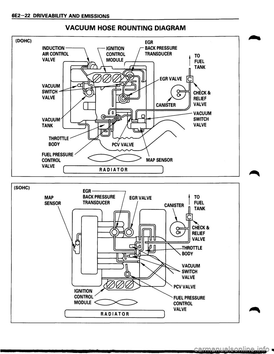
6E2-22 DRIVEABILITV AND EMISSIONS
(DOHC)
(SOHC)
VACUUM HOSE ROUNTING DIAGRAM
EGR
INDUCTION-----
AIR CONTROL
VALVE
BACK PRESSURE
TRANSDUCER
t
TO
THROTTLE
BODY
FUELPRESSURE ~
CONTROL ~ MAPSENSOR
VALVE (..._ _____ R_A_D _I A_T_O_R ____ ___.)
MAP
SENSOR
EGR------,
BACK PRESSURE
TRANSDUCER
FUEL
TANK
VACUUM
SWITCH
VALVE
CHECK&
RELIEF
c:::=::::::::::::::;:T=====!.J VALVE
L-~~~~~ ...J;::...u..-+----'~THROTTLE BODY
IGNITION
CONTROL
MODULE <==><==::>
[ RADIATOR )
~---------------------
VACUUM
SWITCH
VALVE
FUEL PRESSURE
CONTROL
VALVE
..
Page 719 of 1928
DRIVEABILITY AND EMISSIONS 6E2-23
SECTION A
ENGINE COMPONENTS/WIRING DIAGRAMS/DIAGNOSTIC
CHARTS
CONTENTS
On-Board Diagnostic (OBD} System Check . 6E2-23
Basic Procedure . . . . . . . . . . . . . . . . . . . . . 6E2-23
Engine Component Location . . . . . . . . . . 6E2-24
Engine Control Module Wiring
Diagrams . . . . . . . . . . . . . . . . . . . . . . . . . 6E2-26
Engine Control Module (ECM) Connector
Identification . . . . . . . . . . . . . . . . . . . . . 6E2-33
"SCAN TOOL" On-Board Diagnostic (OBD)
System Check . . . . . . . . . . . . . . . . . . . . 6E2-34
On-Board Diagnostic (OBD} System Check . 6E2-36
Won't Flash Diagnostic Trouble Code
(DTC)
12 No "Check Engine" Malfunction
Indicator Lamp (MIL)-Chart A-1 . . . . . . 6E2-38
No Data Link Connector (DLC) Data or
Won't Flash Diagnostic Trouble Code
(DTC)
21 "Check Engine" Malfunction
Indicator Lamp (MIL} "On" Steady-
Chart A-2 . . . . . . . . . . . . . . . . . . . . . . . . . 6E2-40
Engine Crank But Will Not
Run-Chart A-3 . . . . . . . . . . . . . . . . . . . . . 6E2:.....42
Fuel Pump Relay Circuit-Chart A-5 . . . . . 6E2-48
Fuel System Pressure Test-Chart A-7 ..• /6E2-50
Intake Manifold Diagnostic Plate Chart/
A-8 ......................... ,-:· . . . 6E2-56
Diagnostic Trouble Code (DTC~13 /
Heated Oxygen Sensor (H02 Circuit
(Open Grounded Circuit) . . . . . . . . . . . 6E2-58
Diagnostic Trouble Code (D'JiC) 14A
Engine Coolant Temperaiure (ECT}
Sensor Circuit (High -:remperature
Indicated) ....... /. . . . . . . . . . . . . . . . 6E2-60
Diagnostic Trouble P'ode (DTC} 14B
Engine
Coolan·vremperature (ECT)
Sensor Circuit'(Low Temperature
Indicated) ./. . . . . . . . . . . . . . . . . . . . . . . 6E2-62
Diagnostic Jtouble Code (DTC) 21A
Throtti~,.Position (TP) Sensor
Circu)t (Signal Voltage High) . . . . . . . . 6E2-64
Diag.,Ostic Trouble Code (DTC) 21B
Jflrottle Position (TP} Sensor
//Circuit (Signal Voltage Low} ........ 6E2-66
ON-BOARD DIAGNOSTIC (OBD) SYSTEM
CHECK
The "On-Board Diagnostic System Check" verifies the
system is functioning correctly.
Some special
considerations
to keep in mind while making the "On
Board Diagnostic System Check" are:
Diagnostic Trouble Code (DTC(23A
Intake Air Temperature (IAT)
Sensor Circuit (low Temperature
Indicated) ......................... 6E2-68
Diagnostic Trouble Code (DTC) 23B
Intake Air Temperature (IAT)
Sensor Circuit (High Temperature
Indicated) ... / ...................... 6E2-70
Diagnostic T[ouble Code (DTC} 24
Vehicle )!Peed Sensor (VSS} Circuit ... 6E2-72
DiagnostiC Trouble Code (DTC) 32
Exh,tist Gas Recirculation (EGR}
Cir,.Cuit ............................ 6E2-74
Dia,gnostic Trouble Code (DTC} 33A
·Manifold Absolute Pressure (MAP)
Sensor Circuit (Signal Voltage
High-Low Vacuum) ................. 6E2-76
Diagnostic Trouble Code (DTC) 33B
Manifold Absolute Pressure (MAP}
Sensor Circuit (Signal Voltage
Low-High Vacuum) ................. 6E2-78
Diagnostic Trouble Code (DTC) 42
Ignition Control (IC) Circuit . . . . . . . . . . 6E2-80
Diagnostic Trouble Code (DTC} 43
Knock Sensor (KS} Circuit (DOHC) .... 6E2-82
Diagnostic Trouble Code (DTC) 44
Heated Oxygen Sensor (H02S} Circuit
(Lean Heated Oxygen Sensor (H02S)
Signal Indicated} . . . . . . . . . . . . . . . . . . . 6E2-84
Diagnostic Trouble Code (DTC) 45
Heated Oxygen Sensor (H02S) Circuit
(Rich Heated Oxygen Sensor (H02S)
Signal Indicated) . . . . . . . . . . . . . . . . . . . 6E2-86
Diagnostic Trouble Code (DTC) 51
Engine Control Module (ECM} Failure
ECM Failed
or Electrically Erasable
Programmable Read Memory Only
Failure} ........................... 6E2-88
Blocking Drive Wheels
The vehicle drive wheels should always be
blocked
while checking the system.
BASIC PROCEDURE
If the basic information on using the diagnostic
procedures contained in this section has
not been
reviewed, refer
to the introduction of this section.
Page 722 of 1928
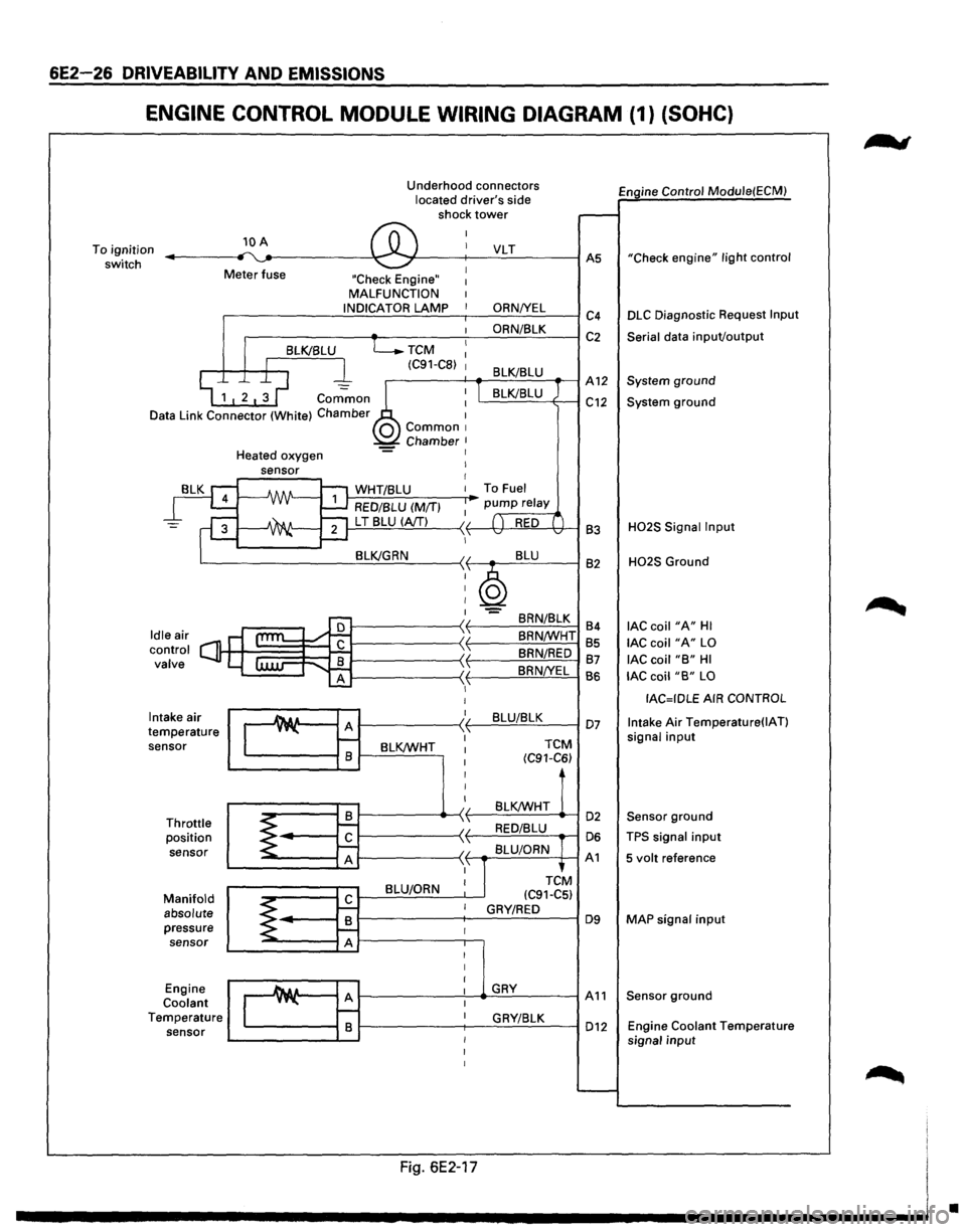
6E2-26 DRIVEABILITV AND EMISSIONS
ENGINE CONTROL MODULE WIRING DIAGRAM (1) (SOHC}
To ignition
switch 10 A
Meter fuse Underhood
connectors
located driver's side
shock tower
"Check Engine" MALFUNCTION
.-----------..:.:.1 N.:.:D:..:.IC=A~T~O:..:.R.:....=:.LA..::.M.:..::P:..___-,--___.:O:..:.R.:.:.N::.._IY.....:E:..:L=----1 c4
.------~~----~~O:..:R:..:N/~8~L=-=K--~ C 2
TCM
(C91-C8)
Engine Control Module(ECM)
"Check
engine" light control
DLC Diagnostic Request Input
Serial
data inpuVoutput
.--------f---+-....::...::;_;__=---_-1 A 12 System ground
Common
Data Link Connector (White) Chamber L.....::.=::....=..:=-=----+---1 C12 System ground
Intake air
temperature sensor
Throttle position
sensor
Manifold absolute pressure sensor
Engine
Coolant Temperature sensor Heated
oxygen
J-,.:..:W:.:..H.:..:T.:.:I8:..:L:.:U:......__ __ ....-To Fuel
RED/BLU (M/T)
1---=-'L T'-.!8~L:!:U'--l(.::::A/T!....!...!....) ---< f------lt+-~!,!..._'H---1 83
BRN/8LK
84
8RN/WHT 85
BRN/RED 87
8RN!YEL
BS
1---------~~~B~L~U~/8~L~K~--I 07
BLK/WHT
TCM
(C91-C6)
BLK/WHT 1------------4>---< t-----=~:..:.:..:_.:..:_ ....... -1 02
1-----------~ f----'-=-'-==--....-1 06
1-----------~ f--.-::..:=.=.:....=..c~-+--1 A 1
BLU/ORN
H02S Signal Input
H02S Ground
lAC coil "A" HI
lAC coil "A" LO
lAC coil "B" HI
lAC coil "B" LO
IAC=IDLE AIR CONTROL
Intake
Air Temperature(IAT)
signal input
Sensor ground
TPS signal input
5 volt reference
MAP
signal input
1---------'----...._.G:=.:..:.RY-=--------1 A 11 Sensor ground
1-------;---.:::G:..:R_;_YI:...::8:..:L::..:K:__---I 012 Engine Coolant Temperature
signal input
Fig. 6E2-17
•
Page 723 of 1928
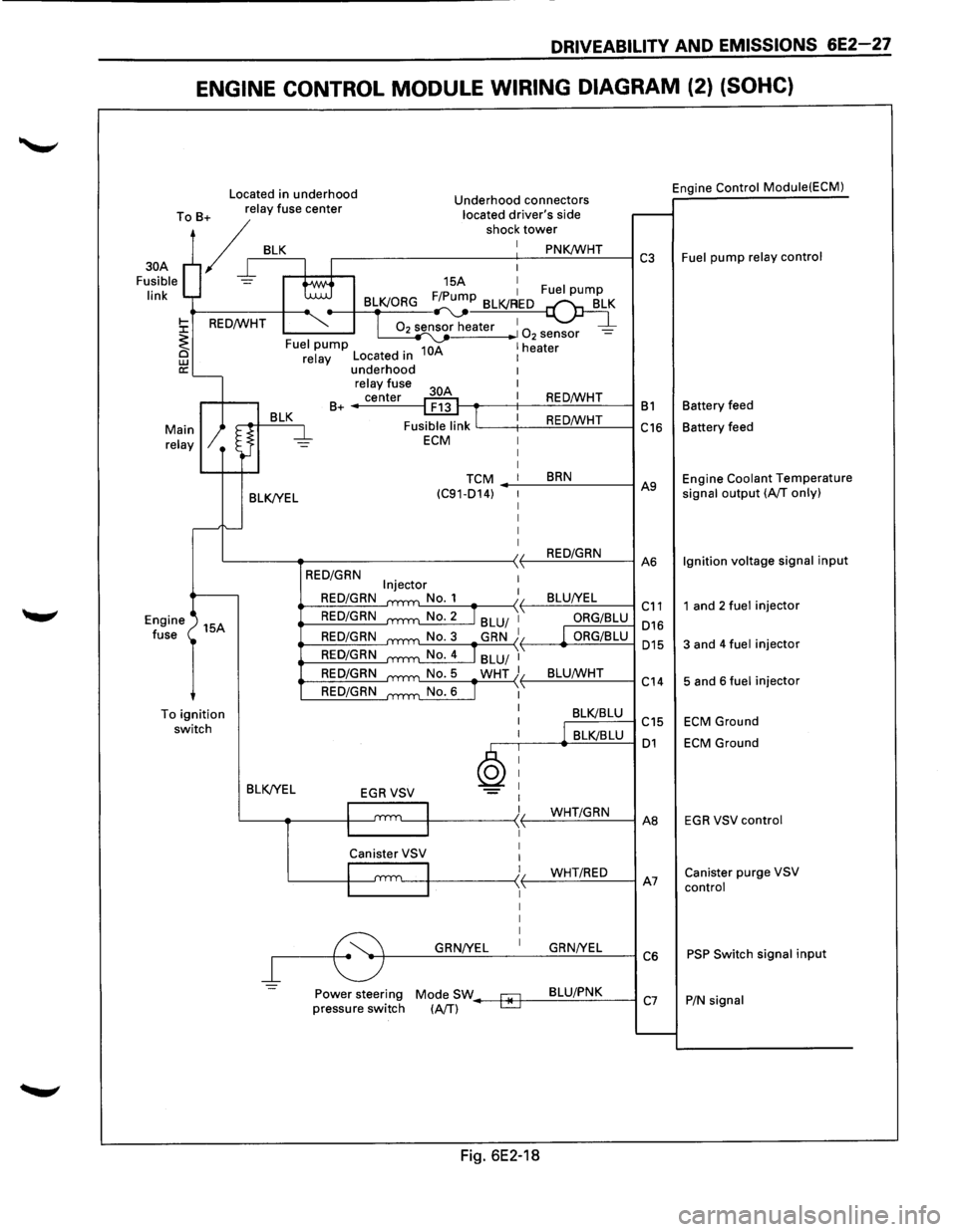
DRIVEABILITY AND EMISSIONS 6E2-27
ENGINE CONTROL MODULE WIRING DIAGRAM (2) (SOHC)
Located in underhood Engine Control
Module(ECM) Underhood connectors
To B+ relay fuse center located driver's side
/r BLK r----------s-ho-c-1-:-t-ow_:_::...:~.:..:K!Wc..:...:..:H:...:T.:..__---I C3 Fuel pump relay control
30A
Fusible
link
15A I F/P 1 Fuel pump BLK/ORG ~~
02 sensor heater 1 1 0 -2 sensor -10A 1 heater Fuel pump
BLK/YEL
relay Located in underhood relay fuse
center
B+ ------1
I
REO/WHT t---.-----t--:..:.::::..=.!...:...:..:..:...:_.:..._--1 B 1 Battery feed
REO/WHT
'-----t--..:.:..::-=:!....:c.:.:...:.-=-------1 C16 Battery feed
TCM BRN (C91-014) -_.:..._--=..:..:..:...:----1 A9 Engine Coolant Temperature signal output (A/T only)
L----~-----------~~-.:..:R.:::EO~/~G~R~N_:_--IA6 Ignition
voltage signal input
Engine
fuse 15A
To
ignition switch BLK/YEL
=
REO/GRN
REO/GRN
REO/GRN
REO/GRN
REO/GRN
REO/GRN
REO/GRN
ORG/BLU 016
ORG/BLU 015
L:...:..::..:-=---.....-:..:.:....:...!._{ L_B::..:L:..:U:c..IW:..:..:...:.HT_:__--l c " 14
BLK/BLU C15
,--.----<.._.:::B.:::LKI=B.::.LU=---1 01
GRN/YEL GRN/YEL
~--~~~~--~~~~--~C6
Power steering Mode SW--+*-f--=-8=-LU~/.:..P.:..:N~K:___---l pressure switch (A/T) C7
Fig. 6E2-18
1 and 2 fuel injector
3 and 4 fuel injector
5 and 6 fuel injector
ECM Ground
ECM Ground
EGR VSV control
Canister purge VSV
control
PSP Switch signal input
P/N signal
Page 724 of 1928
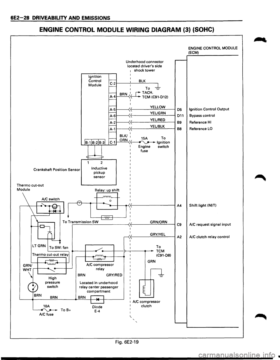
6E2-28 DRIVEABILITV AND EMISSIONS
ENGINE CONTROL MODULE WIRING DIAGRAM (3) (SOHC)
Ignition Control
Module Underhood
connector
located driver's side
1 shock tower I I 1:-2~--~~--~B~L~K~--~
- : To -4-
-BRN 1. r--TACH.
A-4 ~ TCM IC91-D12) -I
I
YELLOW
·~ YEL!GRN \ VEL/RED YEL!BLK
I--B-1IB-2IB-3l C-1
l
1 2
Crankshaft Position Sensor Inductive pickup
sensor I
I
I
I
Thermo cut-out I
I
I
I
I
n I
Mo\\I•Silj ~~
To Transmission SW ~ r-------------------~ -
'---<
LT GRN To SW: fan
Thermo cut-out relay'
GRN/
WHT
....--+-----~
BRN
High
pressure switch
BRN
NC compressor relay
BRN GRY/RED
Located in underhood relay center passenger
compartment
BRN r::-1
I
I
r
I
I
I
I
I
I
I
I
I
I
I
I
I
I
GRN/ORN
GRY!YEL To
TCM IC91-D8)
GRN
n
l
I I 1 NC compressor 10A ~ToB+ NCfuse
Diode E-4
I clutch I
I
' ' '
Fig. 6E2-19
A4
C9
A2
~
ENGINE CONTROL MODULE (ECM)
Reference HI
Reference LO
Shift light (MfT)
NC request signal input
NC clutch relay control
..
Page 725 of 1928
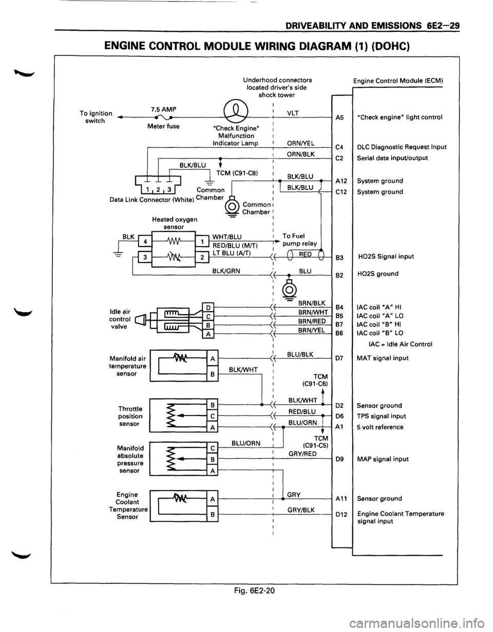
DRIVEABILITY AND EMISSIONS 6E2-29
ENGINE CONTROL MODULE WIRING DIAGRAM (1) (DOHC)
Underhood connectors
located driver's side
shock
tower
To ignition
switch 7.5AMP ,.... ~ ®
I
I
Meter fuse I "Check Engine" I Malfunction I Indicator Lamp I
I
'
I 8LK/8LU I
D
I l TCM (C91-C8) 1
~ 1 2 ~ ~ co.;;mo~~ : ata Link Connector (White) Chamber 1 0 Common1 Chamber 1 Heated oxygen -= I
rg
=F
leair s ontrol C] alve
ld c v
M
te anifold
air
mperature sensor
Throttle position sensor
Manifold absolute pressure sensor
Engine
Coolant
T emperature
Sensor
sensor I
I
-A/IN-1:'1 WHT/8LU I
~ RED/8LU (M/TI I
~ ""21 L T 8LU (A/TI II ....::....1 ,1,
8LK/GRN :,
I
I
I
I
cam l:
I
I
Au A )I y"-\1 r--
8 8LK/WHT I I
I
I
I
8 ~ 1--II
~ r£ \ 'I A ,1,
8LU/ORN I
r£ ~ I
8 ~ f--I A I
I
I
_A& a A I y"-I r--I 8 I
I
I
Fig. 6E2-20
VLT
ORNNEL
ORN/8LK
8LK/8LU
I 8LK/8LU
To Fuel
pump relay
( ) RED ( v v
8LU
~ -8RN/8LK
8RN/WHT
8RN/RED
8RNNEL
8LU/8LK
TCM (C91-C6)
8LK/WHT !
RED/8LU
8LU/ORN
TCtM
(C91-C5)
GRY/RED
GRY
GRY/8LK Engine
Control
Module (ECMI
.-----
AS "Check engine" light control
C4 DLC Diagnostic Request lnpu
C2 Serial data input/output
A12 System ground
C12 System ground
83
H02S Signal input
82 H02S ground
84
lAC coil "A" HI
85 lAC coil "A" LO
87 lAC coil "8" HI
86 lAC coil "8" LO
lAC = Idle Air Control
D7 MAT signal input
D2 Sensor ground
D6 TPS signal input
A1 5 volt reference
D9 MAP signal input
A11 Sensor ground
D12 Engine Coolant Temperatur e signal input
......__