ISUZU TROOPER 1995 Owners Manual
Manufacturer: ISUZU, Model Year: 1995, Model line: TROOPER, Model: ISUZU TROOPER 1995Pages: 1928
Page 91 of 1928
COMPRESSOR OVERHAUL 10-3
GENERAL INFORMATION
COMPRESSOR OIL
OIL SPECIFICATION
• The HFC-134a system requires a synthetic
(PAG) compressor oil whereas the R-12 system
requires a
mineral compressor oil. The two oils
must never be mixed.
• Compressor (PAG) oil varies according to com
pressor model. Be sure to use oil specified for
the model of compressor.
• Always use HFC-134a Vane Rotary Type Com
pressor Oil
(AIPDN Part No. 2-90188-301-0)
HANDLING OF OIL
• The oil should be free from moisture, dust,
metal powder, etc.
• Do not mix with other oil.
•
The water content in the oil increases when
exposed to the air. After use, seal oil from air
immediately.
(HFC-134a Vane Rotary Compressor Oil absorbs
moisture very easily.)
•
The compressor oil must be stored in steel
containers, not in plastic containers.
COMPRESSOR OIL CHECK
The oil used to lubricate the compressor is circul
ating with the refrigerant.
Whenever replacing any component of the system
or a large amount of gas leakage occurs, add oil to
maintain the original amount of oil.
Oil Capacity.
Capacity
total in system 150cc (5.0 fl.oz.)
Compressor (Service
parts)
charging amount 15 0cc (5
·0
fl.oz.)
Checking and Adjusting for Used Compressor
1. Perform Oil return operation.
(Refer to "Oil Return Operation" in this section.)
2. Discharge and recover refrigerant and remove
the compressor.
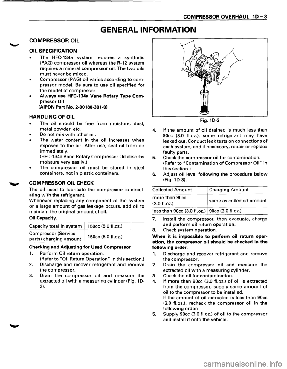
3. Drain the compressor oil and measure the
extracted oil with a measuring cylinder (Fig. 1 D-
2).
Fig. 1D-2
4. If the amount of oil drained is much less than
90cc (3.0 fl.oz.), some refrigerant may have
leaked out. Conduct leak tests on connections of
each system, and if necessary, repair or replace
faulty parts.
5. Check the compressor oil for contamination.
(Refer to "Contamination of Compressor Oil" in
this section.)
6. Adjust oil level following the procedure below
(Fig. 1 D-3).
Collected Amount
more than 90cc
(3.0 fl.oz.)
Charging Amount
same as collected amount
less than 90cc (3.0 fl.oz.) 90cc (3.0 fl.oz.)
7. Install the compressor, then evacuate, charge
and
perform oil return operation.
8. Check system operation.
When it is impossible to perform oil return oper
ation, the compressor oil should be checked in the
following order:
1. Discharge and recover refrigerant and remove
the compressor.
2. Drain the compressor oil and measure the
extracted oil with a measuring cylinder.
3. Check the oil for contamination.
4. If more than 90cc (3.0 fl.oz.) of oil is extracted
from the compressor, supply same amount of
oil to the compressor to be installed.
If
the amount of oil extracted is less than 90cc
(3.0 fl.oz.),
recheck the compressor oil in the
following order:
5. Supply 90cc (3.0 fl.oz.) of oil to the compressor
and install it onto the vehicle.
Page 92 of 1928
1 D-4 COMPRESSOR OVERHAUL
6. Perform oil return operation.
7. Remove the compressor and recheck the
amount of oil.
8. Adjust the compressor oil, if necessary.
Collected Amount
more than 90cc
(3.0
fl.oz.)
Charging Amount
same as collected amount
less than 90cc (3.0 fl.oz.) 90cc (3.0 fl.oz.)
Checking and Adjusting for Compressor
Replacement
150cc (5.0 fl.oz.) of oil is charged in compressor
(service parts).
So it is necessary to drain the
proper
amount of oil from the new compressor.
1. Perform oil return operation.
2. Discharge and recover refrigerant and remove
the compressor.
3. Drain the compressor oil and measure the
extracted
oil.
4. Check the compressor oil for contamination.
5. Adjust oil level as required.
Amount of oil drained
from used compressor
less than 90cc
(3.0
fl.oz.)
Draining amount of oil
from new compressor
Same as drained
amount
more than 90cc (3.0 fl.oz.) 90cc (3.0 fl.oz.)
6. Evacuate, charge and perform oil return oper
ation.
7. Check system operation.
CONTAMINATION OF COMPRESSOR OIL
Unlike engine oil, no cleaning agent is added to the
compressor
oil. Even if the compressor runs for a
long period
of time (approximately 1 season), the
oil never becomes contaminated as long
as there is
nothing
wrong with the compressor or its method
of use.
Inspect the extracted oil for any of the following
conditions:
• The capacity of the oil has increased.
• The oil has changed color to red.
• Foreign substances, metal powder, etc., are
present in the oil.
If any of these conditions exists, compressor oil
is contaminated. Whenever contaminated com
pressor
oil is discovered, the receiver/dryer must
be
replaced.
OIL RETURN OPERATION
There is close affinity between the oil and the
refrigerant. During normal operation, part
of the oil
recirculates
with the refrigerant in the system.
When checking the
amount of oil in the system, or
replacing any component of the system, the com
pressor
must be run in advance for oil return oper
ation. The procedure is as
follows:
1. Open the all doors and engine hood.
2. Start the engine and air conditioning switch is
"ON" and Set the fan control knob at its hig
hest position.
3. Run the compressor for more than 20 minutes
between
800 and 1,000 rpm in order to operate
the system.
4. Stop the engine.
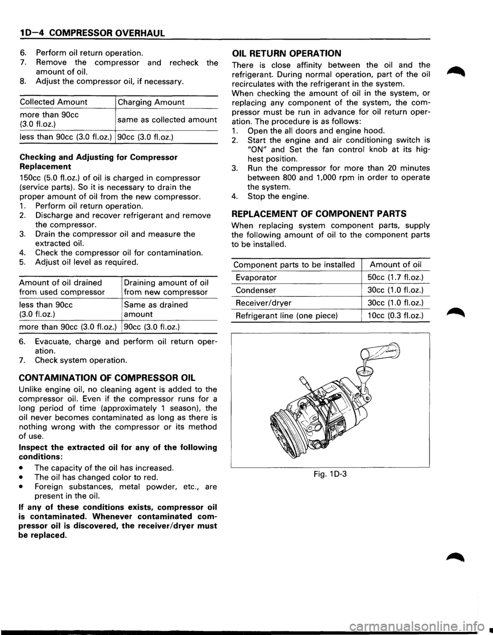
REPLACEMENT OF COMPONENT PARTS
When replacing system component parts, supply
the following
amount of oil to the component parts
to be installed.
Component parts to be installed Amount of oil
Evaporator 50cc
(1.7
fl.oz.)
Condenser 30cc
(1.0 fl.oz.)
Receiver/dryer 30cc
(1.0 fl.oz.)
Refrigerant line (one piece) 1 Occ (0.3 fl. oz.)
Fig. 1 D-3
•
Page 93 of 1928
COMPRESSOR OVERHAUL 1 D-5
SERVICE PROCEDURE
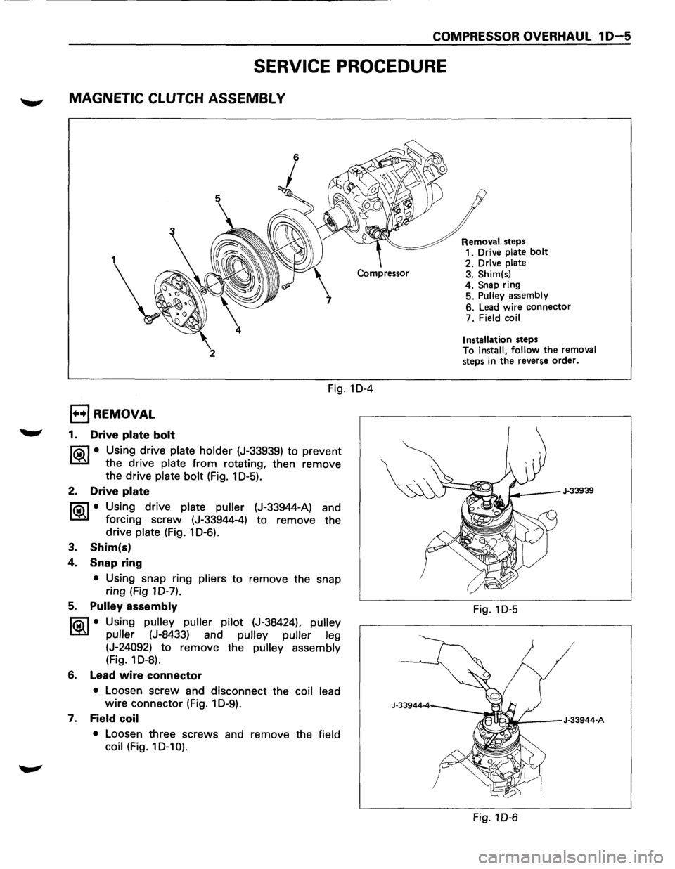
MAGNETIC CLUTCH ASSEMBL V
2
Fig. 10-4
1••1 REMOVAL
1. Drive plate bolt
liC\1 • Using drive plate holder (J-33939) to prevent
~ the drive plate from rotating, then remove
the drive
plate bolt (Fig. 1 0-5).
2. Drive plate
liC\1 • Using drive plate puller (J-33944-A) and
~ forcing screw (J-33944-4) to remove the
drive
plate (Fig. 1 0-6).
3. Shim(s)
4. Snap ring
• Using snap ring pliers to remove the snap
ring (Fig 10-7).
5. Pulley assembly
liC\1 • Using pulley puller pilot (J-38424), pulley
~ puller (J-8433) and pulley puller leg
(J-24092) to remove the pulley assembly
(Fig. 1 0-8).
6. Lead wire connector
• Loosen screw and disconnect the coil lead
wire connector (Fig. 1 0-9).
7. Field coil
• Loosen three screws and remove the field
coil
(Fig. 10-1 0). Removal
steps
1. Drive
plate bolt
2. Drive plate 3. Shim(s)
4. Snap ring
5. Pulley assembly
6. Lead wire connector
7. Field
coil
Installation
steps
To install, follow the removal
steps in the reverse order.
J-33939
Fig. 1 D-5
Fig. 1 D-6
Page 94 of 1928
![ISUZU TROOPER 1995 Owners Manual 1 D-6 COMPRESSOR OVERHAUL
Fig. 1 D-7
Fig. 1D-8
Fig. 1
D-9
Fig. 1D-10
(L!] INSPECTION AND REPAIR
Drive Plate
If the frictional surface shows signs of damage due
to excessive heat, the driv](/img/61/57183/w960_57183-93.png "ISUZU TROOPER 1995 Owners Manual 1 D-6 COMPRESSOR OVERHAUL
Fig. 1 D-7
Fig. 1D-8
Fig. 1
D-9
Fig. 1D-10
(L!] INSPECTION AND REPAIR
Drive Plate
If the frictional surface shows signs of damage due
to excessive heat, the driv")
1 D-6 COMPRESSOR OVERHAUL
Fig. 1 D-7
Fig. 1D-8
Fig. 1
D-9
Fig. 1D-10
(L!] INSPECTION AND REPAIR
Drive Plate
If the frictional surface shows signs of damage due
to excessive heat, the drive plate and pulley should
be replaced.
Pulley Assembly
Check the appearance of the pulley assembly. If the
frictional surface
of the pulley shows signs of
excessive grooving due to slippage, both the pulley
and drive plate should be replaced. The frictional
surfaces
of the pulley assembly should be cleaned
with a suitable solvent before reinstallation.
Coil
Check coil for loose connector or cracked insul
ation.
I••! INSTALLATION
7. Field coil
Align the located portion of the field coil and
compressor (Fig. 1
D-11 ).
Tighten the mounting screw to the specified
torque.
Torque
N·m (lb·in) 5 (44)
Fig. 1D-11
•
Page 95 of 1928
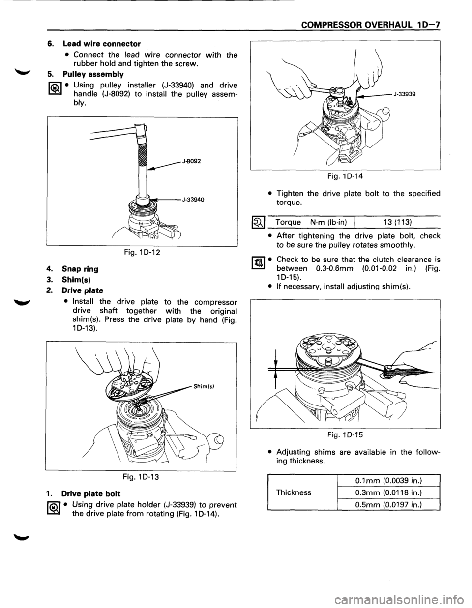
6. Lead wire connector
• Connect the lead wire connector with the
rubber hold and tighten the screw.
5. Pulley assembly
liQ\1 • Using pulley installer (J-33940) and drive
~ handle (J-8092) to install the pulley assem-
bly.
4. Snap ring
3. Shim(s)
2. Drive plate
Fig. 1 D-12
• Install the drive plate to the compressor
drive shaft
together with the original
shim(s). Press the drive
plate by hand (Fig.
10-13).
Fig.1D-13
1. Drive plate bolt
liQ\1 • Using drive plate holder (J-33939) to prevent
~ the drive plate from rotating (Fig. 1 D-14).
COMPRESSOR OVERHAUL 10-7
Fig.1D-14
• Tighten the drive plate bolt to the specified
torque.
~~~ Torque N·m (lb·in) 13(113)
• After tightening the drive plate bolt, check
to be sure the pulley rotates smoothly.
ltm.l• Check to be sure that the clutch clearance is
between
0.3-0.6mm (0.01-0.02 in.) (Fig.
1 D-15).
• If necessary, install adjusting shim(s).
Fig. 1 D-15
• Adjusting shims are available in the follow
ing thickness.
0.1 mm (0.0039 in.)
Thickness
0.3mm (0.0118 in.)
0.5mm (0.0197 in.)
Page 96 of 1928
10-8 COMPRESSOR OVERHAUL
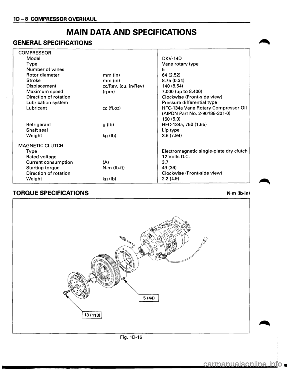
MAIN DATA AND SPECIFICATIONS
GENERAL SPECIFICATIONS
COMPRESSOR
Model
Type
Number of vanes
Rotor
diameter
Stroke
Displacement
Maximum speed
Direction
of rotation
Lubrication system
Lubricant
Refrigerant
Shaft seal
Weight
MAGNETIC CLUTCH
Type
Rated voltage
Current consumption
Starting torque
Direction of rotation
Weight
TORQUE SPECIFICATIONS
mm (in)
mm (in)
cc/Rev. (cu. in/Rev)
(rpm)
cc (fl.oz)
g (lb)
kg (lb)
(A)
N·m (lb·ft)
kg (lb)
Fig. 1D-16 DKV-14D
Vane
rotary type
5 64 (2.52)
8.75
(0.34)
140
(8.54)
7,000 (up to 8,400)
Clockwise
(Front-side view)
Pressure
differential type
HFC-134a Vane Rotary Compressor Oil
(AIPDN
Part No. 2-90188-301-0)
150 (5.0)
HFC-134a, 750 (1.65)
Lip
type
3.6 (7.94)
Electromagnetic single-plate dry clutch
12 Volts D.C.
3.7
49 (36)
Clockwise (Front-side view)
2.2 (4.9)
N·m (lb·in)
•
Page 97 of 1928
COMPRESSOR OVERHAUL 1 D-9
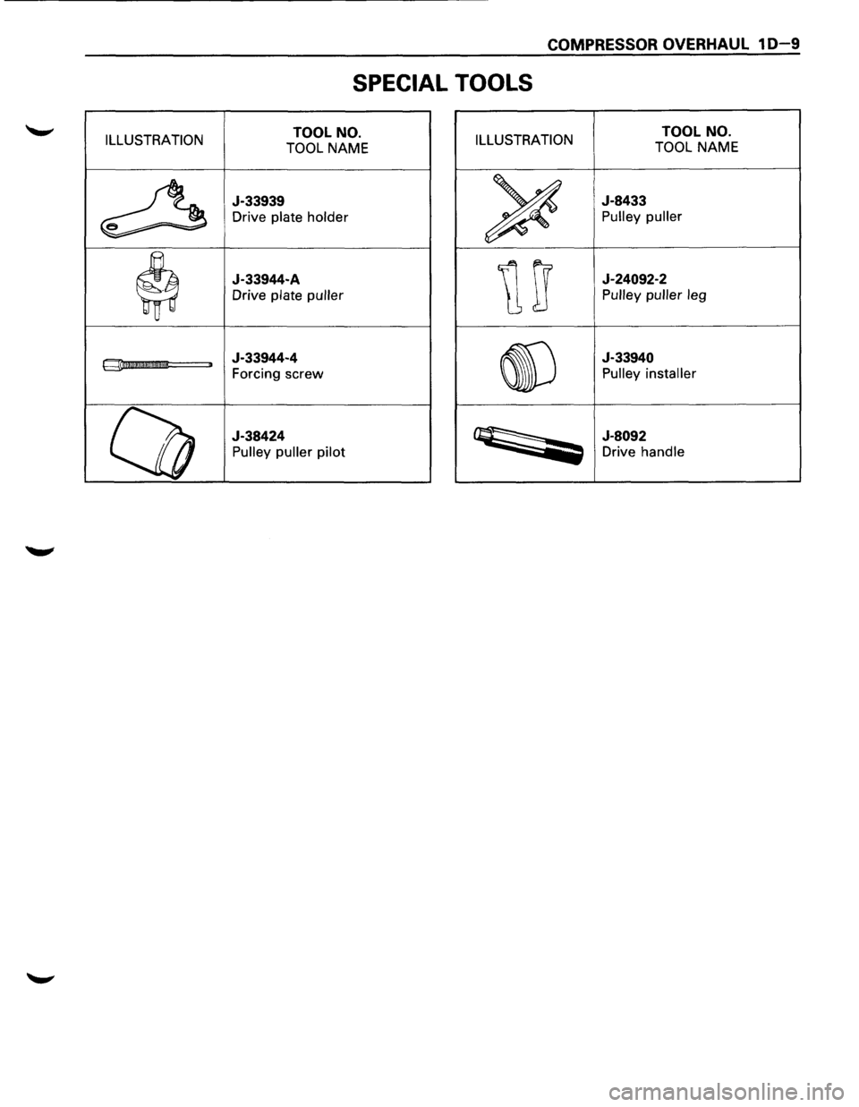
SPECIAL TOOLS
ILLUSTRATION TOOL NO.
TOOL NAME ILLUSTRATION TOOL NO.
TOOL NAME
~
J-33939
Drive plate holder
~
J-8433
Pulley puller
$
J-33944-A
Drive plate puller urr
J-24092-2
Pulley puller leg
gii!I!II!I!I!DII!Im!l!llll!! ,. J-33944-4
Forcing screw
~
J-33940
Pulley installer
(lJ
J-38424
Pulley puller pilot ~
J-8092
Drive handle
Page 98 of 1928
MEMO
•
Page 99 of 1928
FRAME 2A-1
FRAME, BUMPERS AND SHEET METAL
CONTENTS
Frame . . . . . . . . . . . . . . . . . . . . . . . . . . . . . . . . . . . . . . . . . . . . . . . . . . . . . . . . . . . . . . . . . . . . . . . . Section 2A
Bumpers . . . . . . . . . . . . . . . . . . . . . . . . . . . . . . . . . . . . . . . . . . . . . . . . . . . . . . . . . . . . . . . . . . . . . Section
28
Sheet Metal . . . . . . . . . . . . . . . . . . . . . . . . . . . . . . . . . . . . . . . . . . . . . . . . . . . . . . . . . . . . . . . . . . Section 2C
SECTION 2A
FRAME
NOTE:
Fasteners are important attaching parts in that they could affect the performance of vital components and
systems,
and/or could result in major repair expense. They must be replaced with one of the same part number or
with an equivalent part if replacement becomes necessary. Do not use a replacement part of lesser or substitute
design. Torque
values must be used as specified during reassembly to assure proper retention of these parts.
Refer to Torque
Value Chart in the general information of Section "OA".
CONTENTS
General Description ................................................................... 2A-1
Frame Dimensions .................................................................... 2A-2
GENERAL DESCRIPTION
Proper frame alignment is important to assure normal
vehicle life
and performance of many other parts of the
vehicle. If
the vehicle has
been involved in a fire, collision or has
been
overloaded, it is necessary to check the frame
alignment.
•
Page 100 of 1928
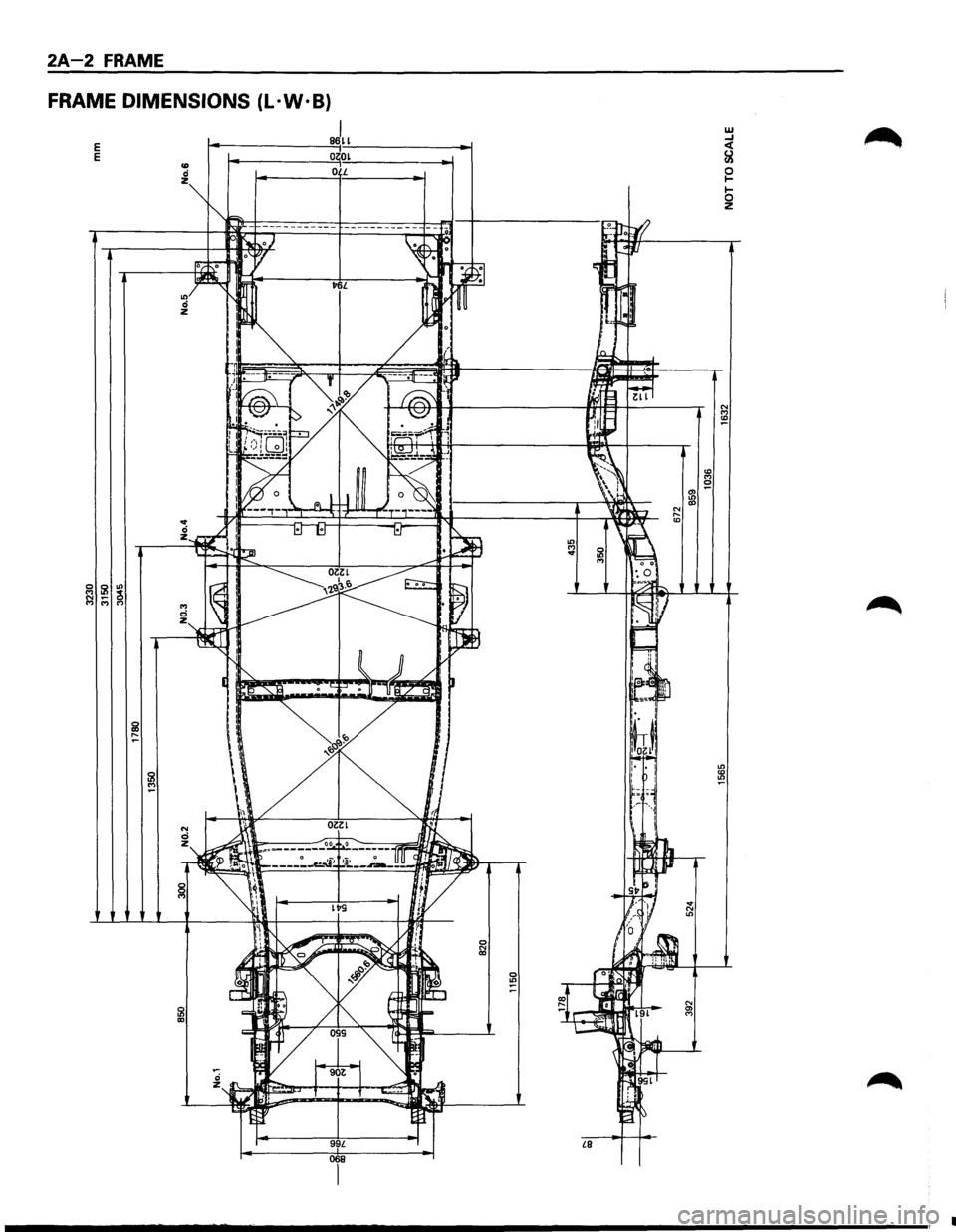
2A-2 FRAME
FRAME DIMENSIONS (L · W ·B)
E E
I 86~1
0 0~ 0 L
99L 068 £8
w ...J < &!
~ 1-0 z
.............................. _______________________________________ , .