ISUZU TROOPER 1995 Repair Manual
Manufacturer: ISUZU, Model Year: 1995, Model line: TROOPER, Model: ISUZU TROOPER 1995Pages: 1928
Page 61 of 1928
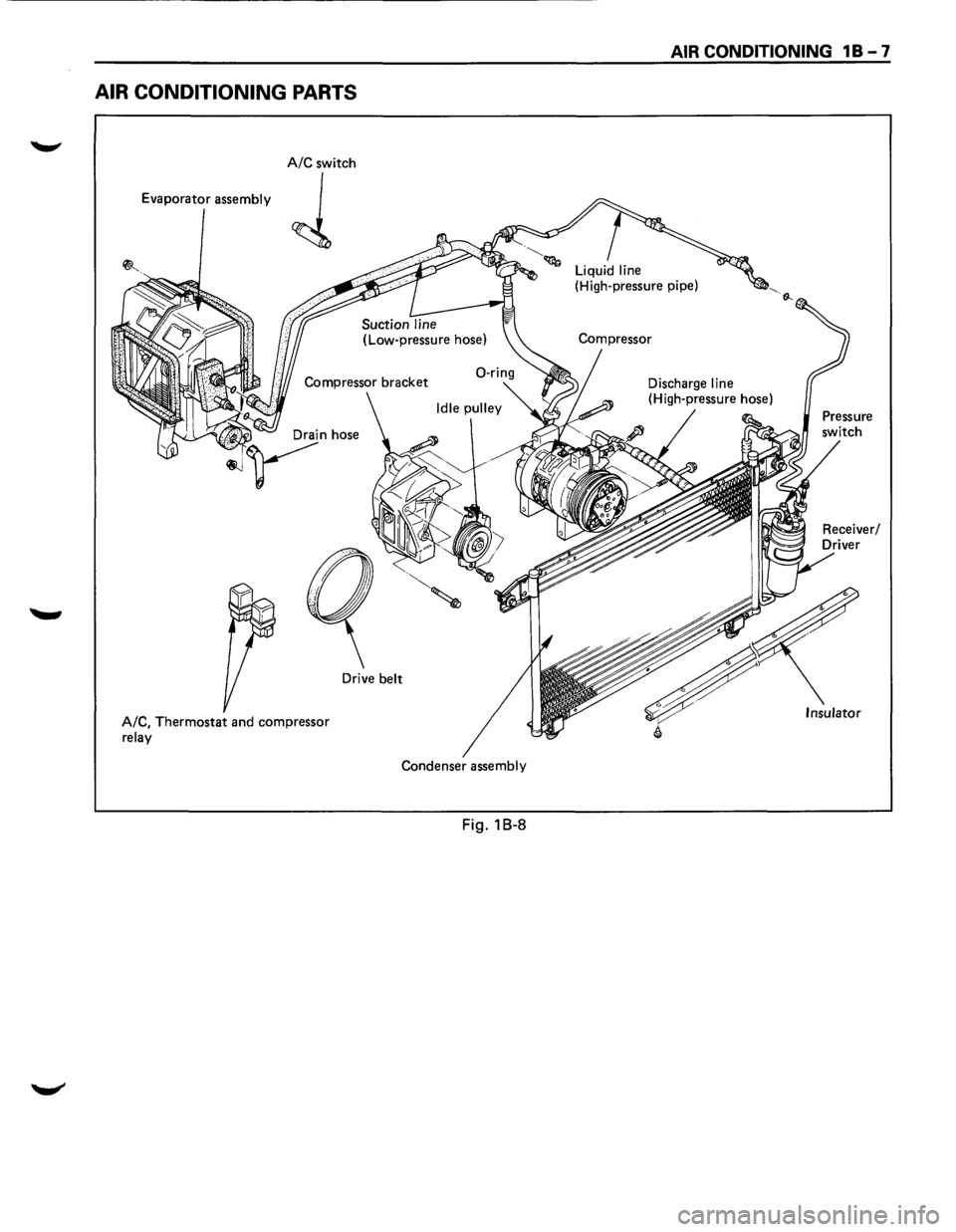
AIR CONDITIONING PARTS
A/C switch
Evaporator
assembly
J
Drive belt
A/C,
Thermostat and compressor relay
Condenser assembly
Fig. 1 B-8
AIR CONDITIONING 1 B - 7
Insulator
Page 62 of 1928
1 B - 8 AIR CONDITIONING
+
RELAY; RESTART
~ ~B BOOV ENG. FRAME
BOOV-Ui II
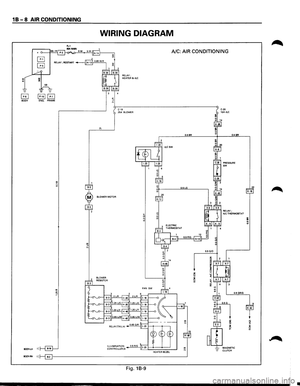
WIRING DIAGRAM
RELAY; HEATER &NC
A/C: AIR CONDITIONING
BOOV~ 11~--------------------------------------------------------------_j
Fig. 18-9
•
Page 63 of 1928
DIAGNOSIS
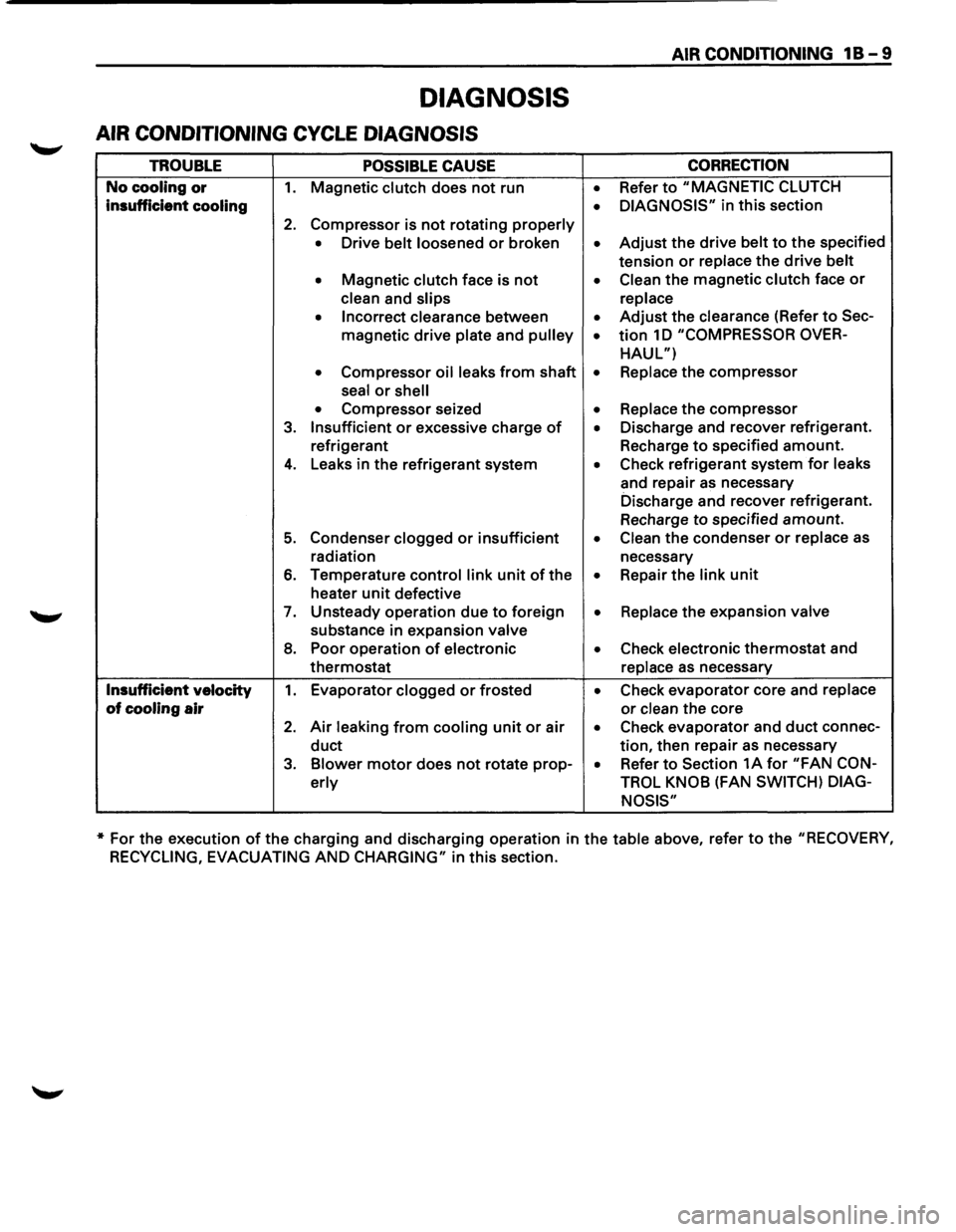
AIR CONDITIONING CYCLE DIAGNOSIS
TROUBLE POSSIBLE CAUSE
No cooling or 1. Magnetic clutch does not run
insufficient cooling
2. Compressor is not rotating properly
• Drive belt loosened or broken
• Magnetic clutch face is not
clean and slips
• Incorrect clearance between
magnetic
drive plate and pulley
• Compressor oil leaks from shaft
seal
or shell
• Compressor seized
3. Insufficient or excessive charge of
refrigerant
4. Leaks in the refrigerant system
5. Condenser clogged or insufficient
radiation
6. Temperature control link unit of the
heater
unit defective
7. Unsteady operation due to foreign
substance in expansion valve
8. Poor operation of electronic
thermostat
Insufficient velocity 1. Evaporator clogged or frosted
of cooling air
2. Air leaking from cooling unit or air
duct
3. Blower motor does not rotate prop-
erly
AIR CONDITIONING 1 B - 9
CORRECTION
• Refer to "MAGNETIC CLUTCH
• DIAGNOSIS" in this section
• Adjust the drive belt to the specified
tension
or replace the drive belt
• Clean the magnetic clutch face or
replace
• Adjust the clearance (Refer to Sec-
• tion 1 D "COMPRESSOR OVER-
HAUL")
• Replace the compressor
• Replace the compressor
• Discharge and recover refrigerant.
Recharge
to specified amount.
• Check refrigerant system for leaks
and repair
as necessary
Discharge and recover refrigerant.
Recharge
to specified amount.
• Clean the condenser or replace as
necessary
• Repair the link unit
• Replace the expansion valve
• Check electronic thermostat and
replace
as necessary
• Check evaporator core and replace
or clean the core
• Check evaporator and duct connec-
tion, then repair as necessary
• Refer to Section 1A for "FAN CON-
TROL KNOB
(FAN SWITCH) DIAG-
NOSIS"
* For the execution of the charging and discharging operation in the table above, refer to the "RECOVERY,
RECYCLING, EVACUATING
AND CHARGING" in this section.
Page 64 of 1928
18-10 AIR CONDITIONING
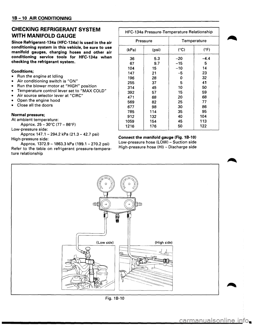
CHECKING REFRIGERANT SYSTEM
WITH MANIFOLD
GAUGE
Since Refrigerant-134a (HFC-134a) is used in the air
conditioning system in this vehicle, be sure to use
manifold gauges, charging hoses and other air
conditioning service tools for HFC-134a when
checking the refrigerant system.
Conditions;
• Run the engine at Idling
• Air conditioning switch is "ON"
• Run the blower motor at "HIGH" position
• Temperature control lever set to "MAX COLD"
•
Air source selector lever at "CIRC"
• Open
the engine hood
• Close all the doors
Normal pressure;
At ambient temperature:
Approx. 25 -30°C (77 -86°F)
Low-pressure side:
Approx 147.1-294.2 kPa (21.3-42.7 psi)
High-pressure side:
Approx. 1372.9-1863.3 kPa (199.1 -270.2 psi}
Refer
to the table on refrigerant pressure-tempera
ture relationship
(Low side)
HFC-134a Pressure-Temperature Relationship
Pressure
Temperature
(kPa) (psi) (oC)
36 5.3 -20
67 9.7 -15
104
15 -10
147 21 -5
196 28 0
255 37 5
314
45 10
392
57 15
471 68 20
569
82 25
677 98 30
785 114 35
912 132
40
1059 154 45
1216
176 50
Connect the manifold gauge (Fig. 18-10)
Low-pressure hose (LOW) -Suction side
High-pressure hose
(HI)-Discharge side
(High side)
(oF)
-4.4
5
14
23
32
41
50
59
68
77
86
95
104
113
122
Fig. 18-10
•
Page 65 of 1928
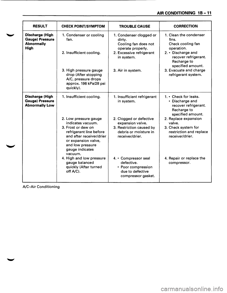
AIR CONDITIONING 1 B -11
RESULT CHECK POINT/SYMPTOM TROUBLE CAUSE CORRECTION
Discharge
(High 1. Condenser or cooling 1. Condenser clogged or 1. Clean the condenser
Gauge) Pressure fan. dirty. fins.
Abnormally Cooling fan does not Check cooling fan
High operate properly. operation.
2. Insufficient cooling. 2. Excessive refrigerant 2. • Discharge and
in system. recover
refrigerant.
Recharge
to
specified amount.
3. High pressure gauge 3. Air in system. 3. Evacuate and charge
drop (After stopping refrigerant system.
A/C, pressure
drops
approx. 196 kPa/28 psi
quickly).
Discharge (High 1. Insufficient cooling. 1. Insufficient refrigerant 1 .• Check for leaks.
Gauge)
Pressure in system. • Discharge and
Abnormally Low recover refrigerant.
Recharge
to
specified amount.
2. Low pressure gauge 2. Clogged or defective 2. Replace expansion
indicates vacuum.
expansion
valve. valve.
3. Frost or dew on 3. Restriction caused by 3. Check system for
refrigerant line before
debris or moisture in restriction
and replace
and after receiver/drier
receiver/drier. receiver/drier.
or expansion valve,
and low pressure
gauge indicates
vacuum.
4. High and low pressure 4. • Compressor seal 4. Repair or replace the
gauge balanced defective. compressor.
quickly (After turned • Poor
compression
off A/C). due to defective
compressor gasket.
A/C-Air Conditioning
Page 66 of 1928
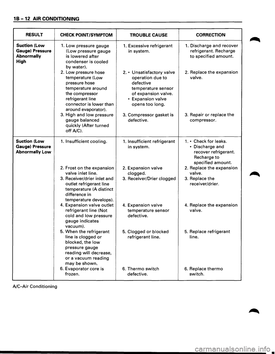
1 B -12 AIR CONDITIONING
RESULT CHECK POINT /SYMPTOM
TROUBLE CAUSE CORRECTION
Suction (low 1. Low pressure
gauge 1. Excessive refrigerant 1. Discharge and recover
Gauge) Pressure (Low pressure gauge
in system. refrigerant.
Recharge
Abnormally is lowered after to specified amount.
High condenser is cooled
by water).
2. Low pressure hose 2. • Unsatisfactory valve 2. Replace the expansion
temperature (Low operation due to valve.
pressure hose
defective
temperature around
temperature sensor
the compressor of expansion valve.
refrigerant line
• Expansion valve
connector is lower than opens too long.
around evaporator).
3. High and low pressure 3. Compressor gasket is 3. Repair or replace the
gauge balanced defective. compressor.
quickly (After turned
off A/C).
Suction (low 1. Insufficient cooling. 1. Insufficient refrigerant 1 .• Check for leaks.
Gauge) Pressure in system. • Discharge and
Abnormally Low recover refrigerant.
Recharge
to
specified amount.
2. Frost on the expansion 2. Expansion valve 2. Replace the expansion
valve inlet line.
clogged. valve.
3. Receiver/drier inlet and 3. Receiver/Drier clogged 3. Replace the
outlet refrigerant line receiver/drier.
temperature (A distinct
difference in
temperature
develops).
4. Expansion valve outlet 4. Expansion valve 4. Replace the expansion
refrigerant line (Not temperature sensor valve.
cold
and low pressure defective.
gauge indicates
vacuum).
5. When the refrigerant 5. Clogged or blocked 5. Replace refrigerant
line is clogged or refrigerant line. line.
blocked,
the low
pressure gauge
reading
will decrease,
or a vacuum reading
may be shown.
6. Evaporator core is 6. Thermo switch 6. Replace thermo
frozen.
defective. switch.
A/C-Air Conditioning
..
Page 67 of 1928
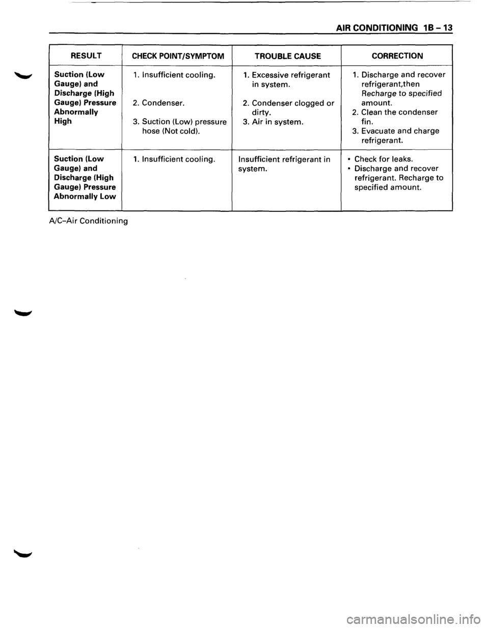
AIR CONDITIONING 1 B -13
RESULT CHECK POINT /SYMPTOM
TROUBLE CAUSE CORRECTION
Suction (low 1. Insufficient cooling. 1. Excessive refrigerant 1. Discharge
and recover
Gauge) and in system. refrigerant, then
Discharge
(High Recharge to specified
Gauge) Pressure 2. Condenser. 2. Condenser clogged or amount.
Abnormally dirty. 2. Clean the condenser
High 3. Suction (Low) pressure 3. Air in system. fin.
hose (Not
cold). 3. Evacuate and charge
refrigerant.
Suction (Low 1. Insufficient cooling. Insufficient refrigerant in • Check for leaks.
Gauge) and system. • Discharge and recover
Discharge (High refrigerant. Recharge to
Gauge) Pressure specified amount.
Abnormally Low
A/C-Air Conditioning
Page 68 of 1928
18-14 AIR CONDITIONING
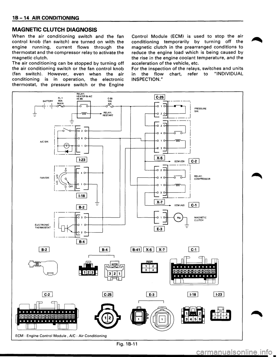
MAGNETIC CLUTCH DIAGNOSIS
When the air conditioning switch and the fan
control knob (fan switch) are turned on with the
engine running, current flows through the
thermostat and the compressor relay to activate the
magnetic clutch.
The air conditioning can be stopped by turning off
the air conditioning switch or the fan control knob
(fan switch). However, even when the air
conditioning is in operation, the electronic
thermostat, the pressure switch or the Engine
BATTER y
~
A/C SW.
FAN SW.
FL-1 BOA MAIN -.Y""'
I
RELAY; HEATER&A/C (8-36)
-
·~
~-----;::: -
I ,--<> -v--ro 2
I 6
! -&r ro 1 l ~ .... --~-'---
11-231
r-g-I 4
I~ 0 I 2 1
l __ 9_ OFF -
lli!J
~
r-----3 I
I 1
I 2 -
ELECTRONIC ~ THERMOSTAT
l __ _
C-20 10A Jd.C
RELAY; RESTART
-=-
ECM -Engine Control Module , NC -Air Conditioning
Control Module (ECM) is used to stop the air
conditioning temporarily by turning off the
magnetic clutch in the prearranged conditions to
reduce the engine load which is being caused by
the rise in the engine coolant temperature, and the
acceleration of the vehicle, etc.
For
the inspection of the relays, switches and units
in the flow chart, refer to "INDIVIDUAL
INSPECTION."
,....-1
2 ......_
.....-=.-2
40. r-
1v-
3
......._ =--
~
I ___ j
PRESSURE
SW.
ECMIC91
~
---2 ----l
•o--
1v-
3
-~-@]
~1
L
[ill
I
I RELAY; COMPRESSOR
I
I I ___ j
ECMIA21 ~
:=:>
MAGNETIC
CLUTCH
,.----I In_ r-r
A1 Kl ., .. ...... A& .. A7 AI ld A10 A11A12 .... •• ., .. a1o an 112
'It!
~
~
Fig.1B-11
Page 69 of 1928
AIR CONDITIONING 1 B -15
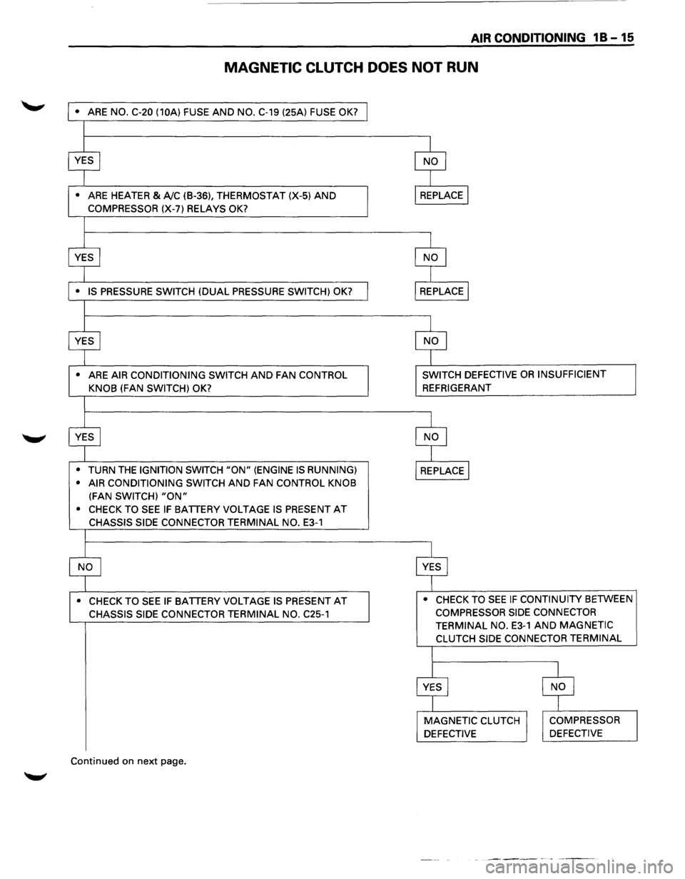
MAGNETIC CLUTCH DOES NOT RUN
• ARE NO. C-20 (10A) FUSE AND NO. C-19 (25A) FUSE OK?
•
ARE HEATER & A!C (B-36), THERMOSTAT (X-5) AND
COMPRESSOR (X-7) RELAYS OK?
•
ARE AIR CONDITIONING SWITCH AND FAN CONTROL
KNOB
(FAN SWITCH) OK?
•
TURN THE IGNITION SWITCH "ON" (ENGINE IS RUNNING)
• AIR CONDITIONING SWITCH
AND FAN CONTROL KNOB
(FAN SWITCH) "ON"
• CHECK TO SEE IF BATTERY VOLTAGE IS PRESENT AT
CHASSIS SIDE CONNECTOR TERMINAL NO. E3-1
• CHECK TO SEE IF BATTERY VOLTAGE IS PRESENT AT
CHASSIS SIDE CONNECTOR TERMINAL NO. C25-1
Continued on next page.
SWITCH DEFECTIVE OR INSUFFICIENT
REFRIGERANT
• CHECK TO
SEE IF CONTINUITY BETWEEN
COMPRESSOR SIDE CONNECTOR
TERMINAL NO.
E3-1 AND MAGNETIC
CLUTCH SIDE CONNECTOR TERMINAL
Page 70 of 1928
1 B -16 AIR CONDITIONING
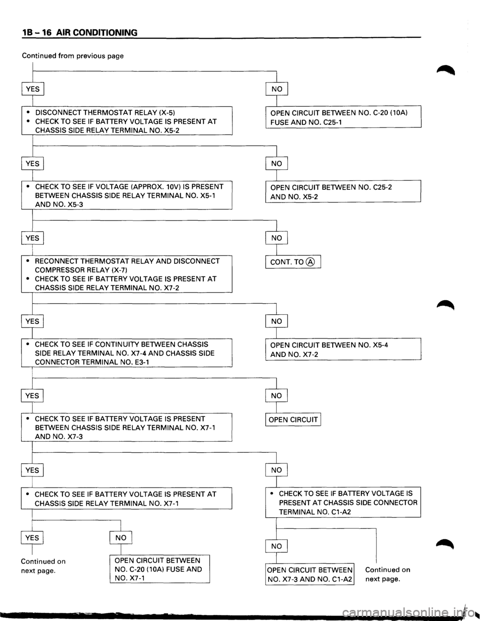
Continued from previous page
• DISCONNECT THERMOSTAT RELAY (X-5)
• CHECK TO SEE IF BATTERY VOLTAGE IS PRESENT AT
CHASSIS SIDE RELAY TERMINAL NO. X5-2
• CHECK TO SEE IF VOLTAGE (APPROX. 10V) IS PRESENT
BETWEEN CHASSIS SIDE RELAY TERMINAL NO. X5-1
AND NO. X5-3
• RECONNECT THERMOSTAT RELAY AND DISCONNECT
COMPRESSOR
RELAY (X-7)
• CHECK TO SEE IF BATTERY VOLTAGE IS PRESENT AT
CHASSIS SIDE RELAY TERMINAL NO. X7-2
• CHECK TO SEE IF CONTINUITY BETWEEN CHASSIS
SIDE
RELAY TERMINAL NO. X7-4 AND CHASSIS SIDE
CONNECTOR TERMINAL NO. E3-1
• CHECK TO SEE IF BATTERY VOLTAGE IS PRESENT
BETWEEN CHASSIS SIDE RELAY TERMINAL NO. X7-1
AND NO. X7-3
• CHECK TO SEE IF BATTERY VOLTAGE IS PRESENT AT
CHASSIS SIDE RELAY TERMINAL NO. X7-1
Continued on
next page. OPEN
CIRCUIT BETWEEN
NO. C-20 (10A)
FUSE AND
NO. X7-1 OPEN
CIRCUIT BETWEEN
NO. C-20 (10A)
FUSE AND NO. C25-1
AND NO. X5-2
AND NO. X7-2
• CHECK TO SEE IF BATTERY VOLTAGE IS
PRESENT AT CHASSIS SIDE CONNECTOR
TERMINAL NO. C1-A2
Continued on
NO. X7-3 AND NO. C1-A2 next page.