ISUZU TROOPER 1995 Workshop Manual
Manufacturer: ISUZU, Model Year: 1995, Model line: TROOPER, Model: ISUZU TROOPER 1995Pages: 1928
Page 101 of 1928
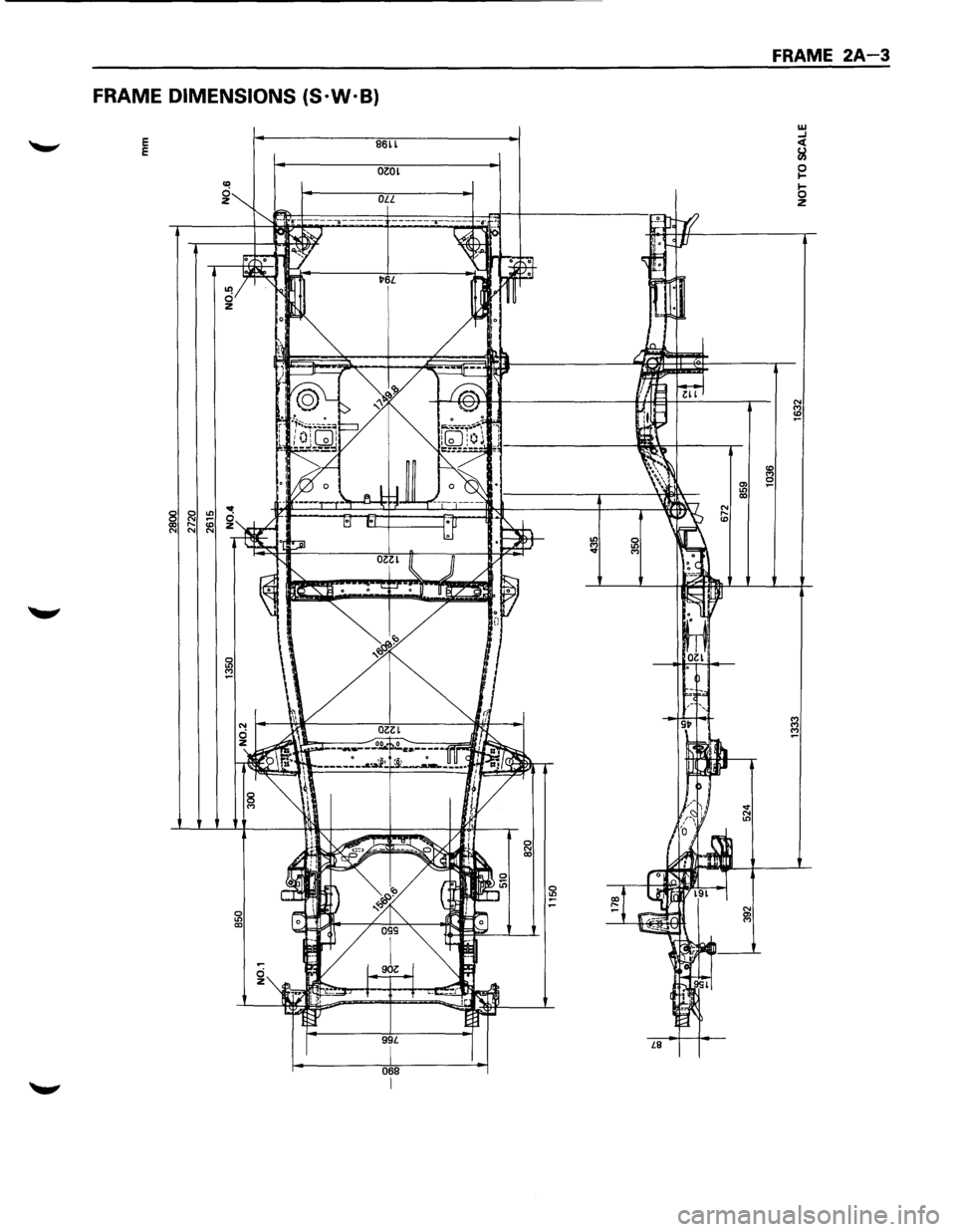
FRAME DIMENSIONS (S·W·B)
E E B6ll
OZOL
068
FRAME 2A-3
w ....1 <( &l
~
b z
Page 102 of 1928
MEMO
•
Page 103 of 1928
BUMPERS 28-1
SECTION 28
BUMPERS
NOTE:
Fasteners are important attaching parts in that they could affect the performance of vital components and
systems,
and/or could result in major repair expense. They must be replaced with one ofthe same part number
or with an equivalent part if replacement becomes necessary. Do not use a replacement part of lesser or
substitute design. Torque values must be used as specified during reassembly to assure proper retention of
these parts. Refer to Torque Value Chart in the general information of Section "OA".
CONTENTS
General Description ................................ 2B-1 Front Bumper ....................................... 2B-2
On-Vehicle Service ................................. 2B-2
Rear Bumper ........................................ 2B-4
GENERAL DESCRIPTION
This section describes how to remove and install front
and rear bumpers. Each bumper is installed with two
fixing bolts used on either side to fasten backbar to
the frame, a slider is used to fasten the bumper fascia
tothe fender panel. The bumpers can be removed by
taking them out forward or backward after removing
the two fixing bolts on either side.
Page 104 of 1928
28-2 BUMPERS
FRONT BUMPER
ON-VEHICLE SERVICE
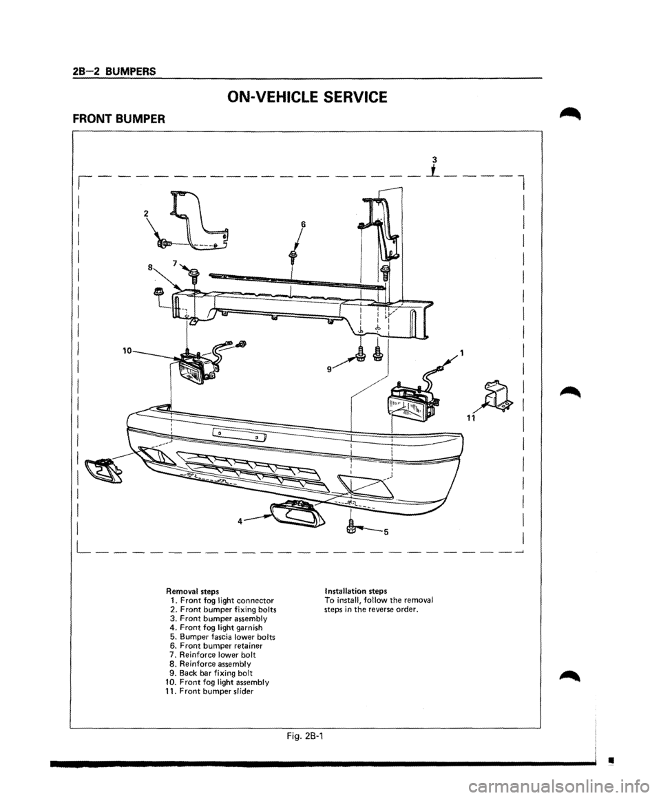
Removal steps 1. Front fog llght connector 2. Front bumper fixing bolts 3. Front bumper assembly 4. Front fog light garnish
5. Bumper fascia lower bolts 6. Front bumper retainer 7. Reinforce lower bolt 8. Reinforce assembly
9. Back bar fixing bolt
10. Front fog light assembly 11. Front bumper slider
Fig. 2B-1
Installation steps To install, follow the removal steps in the reverse order.
•
Page 105 of 1928
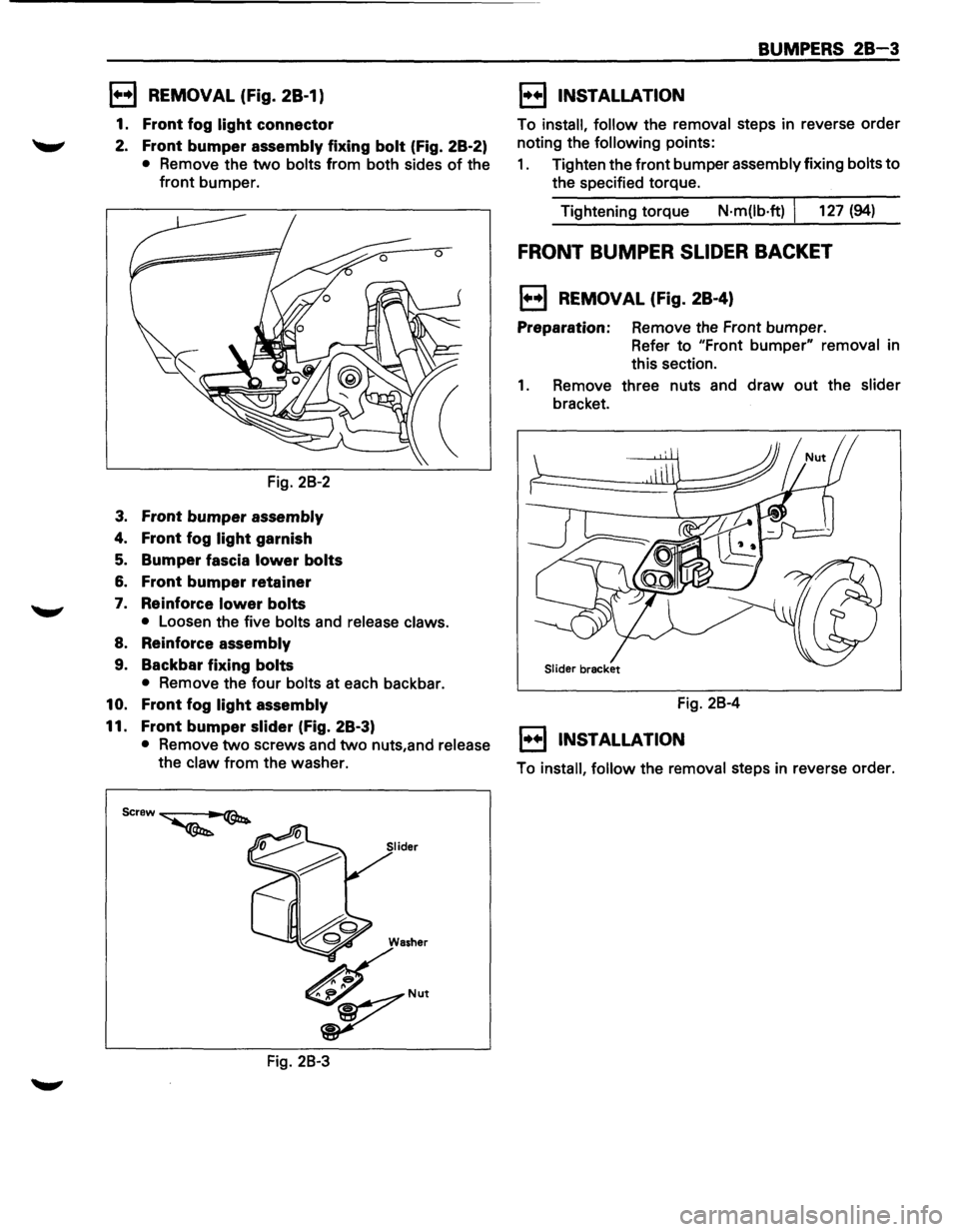
1••1 REMOVAL (Fig. 28-1)
1. Front fog light connector
2. Front bumper assembly fixing bolt (Fig. 28-2)
• Remove the two bolts from both sides of the
front bumper.
Fig. 28-2
3. Front bumper assembly
4. Front fog light garnish
5. Bumper fascia lower bolts
6. Front bumper retainer
7. Reinforce lower bolts
• Loosen the five bolts and release claws.
8. Reinforce assembly
9. Backbar fixing bolts
• Remove the four bolts at each backbar.
10. Front fog light assembly
11. Front bumper slider (fig. 28-3)
• Remove two screws and two nuts,and release
the claw from the washer.
Fig. 28-3
BUMPERS 28-3
1••1 INSTALLATION
To install, follow the removal steps in reverse order
noting the
following points:
1. Tighten the front bumper assembly fixing bolts to
the specified torque.
Tightening torque
N·m(lb·ft) I 127 (94)
FRONT BUMPER SLIDER BACKET
1••1 REMOVAL (Fig. 28-4)
Preparation: Remove the Front bumper.
Refer to "Front
bumper" removal in
this section.
1. Remove three nuts and draw out the slider
bracket.
Fig. 28-4
1••1 INSTALLATION
To install, follow the removal steps in reverse order.
Page 106 of 1928
28-4 BUMPERS
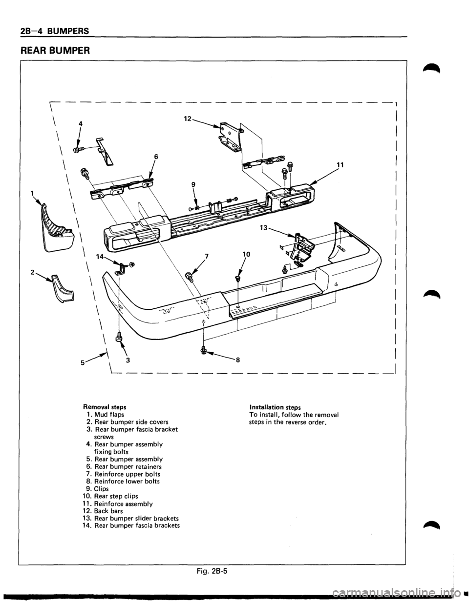
REAR BUMPER
1 4
~ 6
Removal steps
1.
Mud flaps
2. Rear
bumper side covers 3. Rear bumper fascia bracket screws
4. Rear bumper assembly
fixing bolts
5. Rear
bumper assembly
6. Rear bumper retainers
7. Reinforce upper bolts
8. Reinforce lower bolts
9.
Clips
10. Rear step clips
11. Reinforce assembly
12. Back bars
13. Rear
bumper slider brackets
14. Rear bumper fascia brackets
12
Fig. 28-5
Installation steps
To install, follow the removal
steps in the reverse order.
-,
I
I
I
I
I
I
I
I
I
I
I
I
I
I
I
I
I
__ I
•
Page 107 of 1928
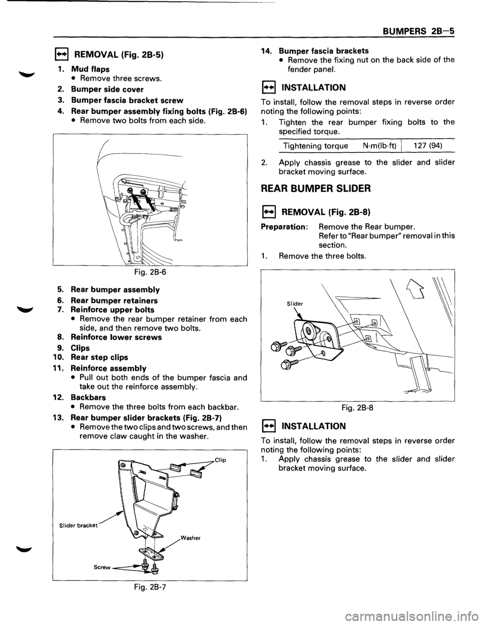
1••1 REMOVAL (Fig. 28-5)
1. Mud flaps
• Remove three screws.
2. Bumper side cover
3. Bumper fascia bracket screw
4. Rear bumper assembly fixing bolts (Fig. 2B-6)
• Remove two bolts from each side.
Fig. 28-6
5. Rear bumper assembly
6. Rear bumper retainers
7. Reinforce upper bolts
• Remove the rear bumper retainer from each
side, and then remove
two bolts.
8. Reinforce lower screws
9. Clips
10.
Rear step clips
11. Reinforce assembly
• Pull out both ends of the bumper fascia and
take
out the reinforce assembly.
12. Backbars
• Remove the three bolts from each backbar.
13. Rear bumper slider brackets (Fig. 2B-7)
• Remove the two clips and two screws, and then
remove
claw caught in the washer.
Slider bracket
Fig. 28-7
BUMPERS 28-5
14. Bumper fascia brackets
• Remove the fixing nut on the back side of the
fender
panel.
1••1 INSTALLATION
To install, follow the removal steps in reverse order
noting the
following points:
1. Tighten the rear bumper fixing bolts to the
specified torque.
Tightening torque
N·m(lb·ft) 127 (94)
2. Apply chassis grease to the slider and slider
bracket moving surface.
REAR BUMPER SLIDER
1••1 REMOVAL (Fig. 28-8)
Preparation: Remove the Rear bumper.
Refer to
"Rear bumper" removal in this
section.
1. Remove the three bolts.
Fig. 28-8
1••1 INSTALLATION
To install, follow the removal steps in reverse order
noting the
following points:
1. Apply chassis grease to the slider and slider
bracket moving surface.
Page 108 of 1928
MEMO
Page 109 of 1928
SHEET METAL 2C-1
SECTION 2C
SHEET METAL
NOTE:
Fasteners are important attaching parts in that they could affect the performance of vital components and
systems,
and/or could result in major repair expense. They must be replaced with one of the same part number or
with an equivalent part if replacement becomes necessary. Do not use a replacement part of lesser quality or
substitute design. Torque values must be used as specified during reassembly to assure proper retention of these
parts. Refer
to Torque Value Chart in the general information of Section "OA".
CONTENTS
General Description . . . . . . . . . . . . . . . . . . . . 2C-1
On-Vehicle Service . . . . . . . . . . . . . . . . . . . . 2C-2
Cowl Cover . . . . . . . . . . . . . . . . . . . . . . . . . 2C-2
Engine Hood . . . . . . . . . . . . . . . . . . . . . . . . 2C-3
Engine Hood Hinge . . . . . . . . . . . . . . . . . . 2C-4
Engine Hood Lock .................... 2C-5
Radiator Grill and Front end
Lower Panel
....................... 2C-6
Front Fender Panel ................... 2C-7
Body Mounting ...................... 2C-9
GENERAL DESCRIPTION
This section includes items of front end sheet metal
that are attached by bolts, screws
or clips and related
accessory components.
Anti-corrosion materials have been applied to the
interior surfaces
of some metal panels to provide rust resistance.
When servicing these panels, areas on
which this material has been disturbed should
be
properly recoated with service-type anti-corrosion
material.
Page 110 of 1928
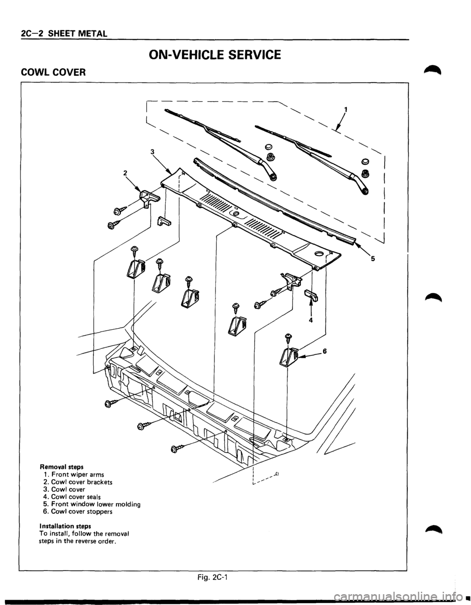
2C-2 SHEET METAL
COWL COVER
Removal steps
1. Front wiper arms
2.
Cowl cover brackets 3. Cowl cover
4. Cowl cover seals 5. Front window lower molding 6. Cowl cover stoppers
Installation steps
To install, follow the removal steps in the reverse order.
ON-VEHICLE SERVICE
4
Fig. 2C-1
•