ISUZU TROOPER 1995 Workshop Manual
Manufacturer: ISUZU, Model Year: 1995, Model line: TROOPER, Model: ISUZU TROOPER 1995Pages: 1928
Page 111 of 1928
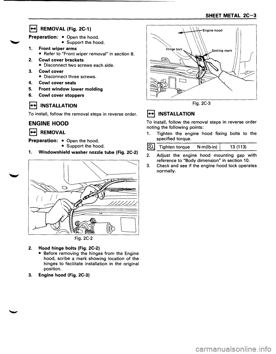
1••1 REMOVAL (Fig. 2C-1)
Preparation: • Open the hood.
'-"' • Support the hood.
1. Front wiper arms
• Refer to "Front wiper removal" in section 8.
2. Cowl cover brackets
• Disconnect two screws each side.
3. Cowl cover
• Disconnect three screws.
4. Cowl cover seals
5. Front window lower molding
6. Cowl cover stoppers
I•• I INSTALLATION
To install, follow the removal steps in reverse order.
ENGINE HOOD
1••1 REMOVAL
Preparation: • Open the hood.
• Support the hood.
1. Windowshield washer nozzle tube (Fig. 2C-2)
( f
0
Fig. 2C-2
2. Hood hinge bolts (Fig. 2C-2)
• Before removing the hinges from the Engine
hood, scribe a mark showing
location of the
hinges
to facilitate installation in the original
position.
3. Engine hood (Fig. 2C-3)
SHEET METAL 2C-3
Fig. 2C-3
1••1 INSTALLATION
To install, follow the removal steps in reverse order
noting the following points:
1. Tighten the engine hood fixing bolts to the
specified torque.
1~1 Tighten torque N·m(lb·in) I 13 (113)
2. Adjust the engine hood mounting gap with
reference to "Body dimension" in section 10.
3. Check and see if the engine hood lock operates
normally.
Page 112 of 1928
2C-4 SHEET METAL
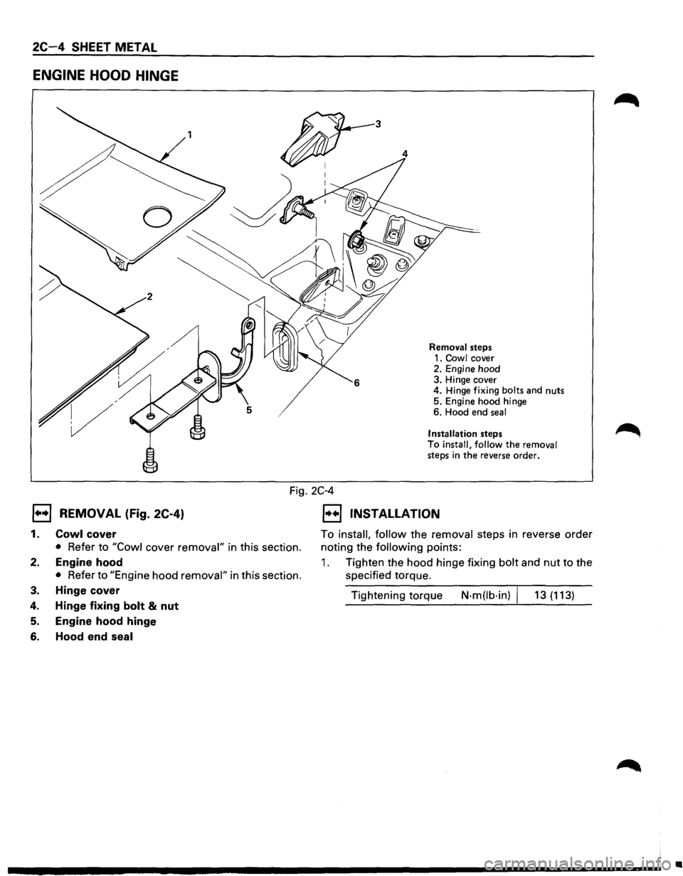
ENGINE HOOD HINGE
3
4
Removal steps
1. Cowl cover
2. Engine hood
3. Hinge cover
4. Hinge
fixing bolts and nuts
5. Engine hood hinge
6. Hood end
seal
Installation steps To install, follow the removal steps in the reverse order.
Fig. 2C-4
1••1 REMOVAL (fig. 2C-4)
1. Cowl cover
• Refer to "Cowl cover removal" in this section.
2. Engine hood
• Refer to "Engine hood removal" in this section.
3. Hinge cover
4. Hinge fixing bolt & nut
5. Engine hood hinge
6. Hood end seal
1••1 INSTALLATION
To install, follow the removal steps in reverse order
noting the following points:
1. Tighten the hood hinge fixing bolt and nut to the
specified torque.
Tightening torque
N·m(lb·in) I 13 (113)
•
Page 113 of 1928
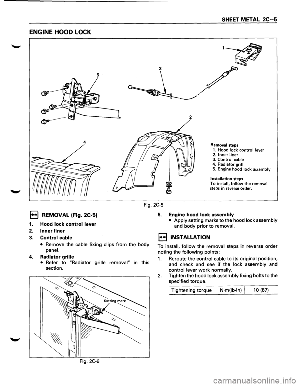
ENGINE HOOD LOCK
5
2
4
SHEET METAL 2C-5
Removal steps
1. Hood lock control lever
2. Inner liner
3. Control cable
4. Radiator
grill
5. Engine hood lock assembly
Installation steps
To install, follow the removal
steps in reverse order.
Fig. 2C-5
1••1 REMOVAL (Fig. 2C-5)
1. Hood lock control lever
2. Inner liner
3. Control cable
• Remove the cable fixing clips from the body
panel.
4. Radiator grille
• Refer to "Radiator grille removal" in this
section.
Fig.
2C-6
5. Engine hood lock assembly
• Apply setting marks to the hood lock assembly
and body prior to removal.
EJ INSTALLATION
To install, follow the removal steps in reverse order
noting the
following points:
1. Reroute the control cable to its original position,
and check and see if the
lock assembly and
control lever work normally.
2. Tighten the hood lock assembly fixing bolts to the
specified torque.
Tightening torque
N·m(lb·in) I 10 (87)
Page 114 of 1928
2C-6 SHEET METAL
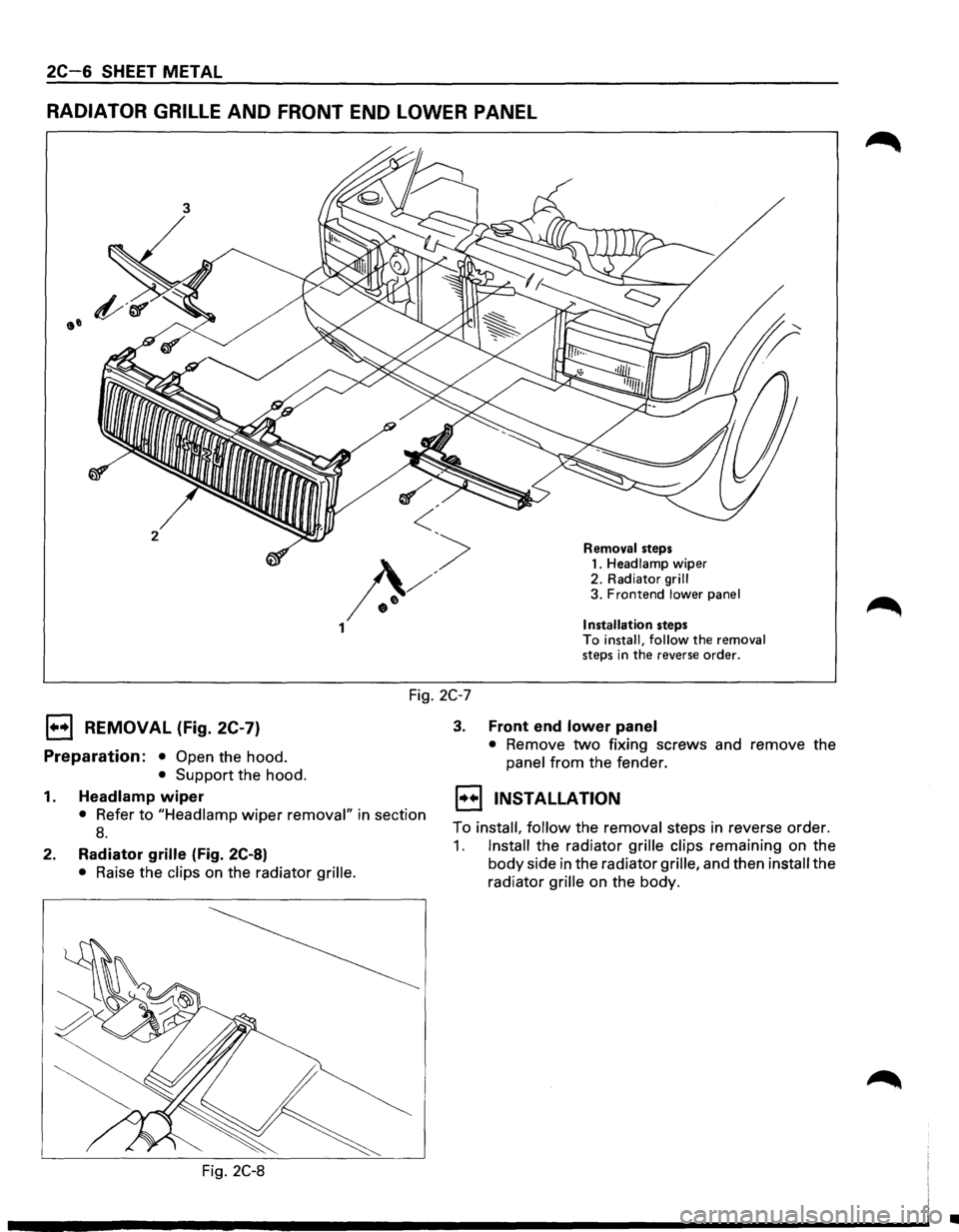
RADIATOR GRILLE AND FRONT END LOWER PANEL
3
2 Removal steps 1. Headlamp wiper
2. Radiator
grill 3. Frontend lower panel
Installation steps To install, follow the removal steps in the reverse order.
Fig. 2C-7
1••1 REMOVAL (Fig. 2C-7)
Preparation: • Open the hood.
• Support the hood.
1.
Headlamp wiper
• Refer to "Headlamp wiper removal" in section
8.
2. Radiator grille (Fig. 2C-8)
• Raise the clips on the radiator grille.
Fig. 2C-8
3. Front end lower panel
•
Remove two fixing screws and remove the
panel from the fender.
1••1 INSTALLATION
To install, follow the removal steps in reverse order.
1. Install the radiator grille clips remaining on the
body side in the radiator
grille, and then install the
radiator
grille on the body.
•
Page 115 of 1928
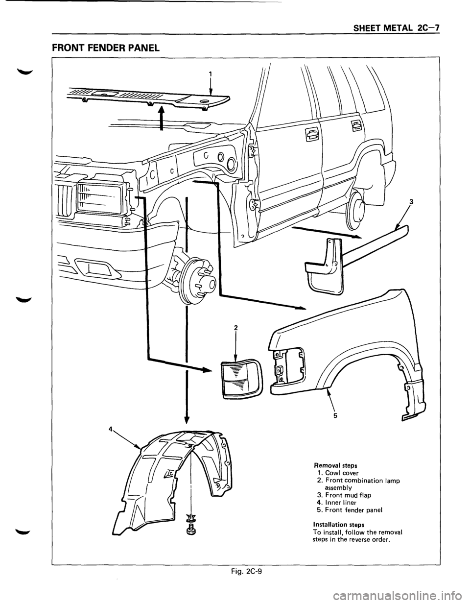
FRONT FENDER PANEL
Fig. 2C-9
SHEET METAL 2C-7
Removal steps
1. Cowl cover
2.
Front combination lamp
assembly
3. Front mud flap 4. Inner liner 5. Front fender panel
Installation
steps
To
install, follow the removal steps in the reverse order.
Page 116 of 1928
2C-8 SHEET METAL
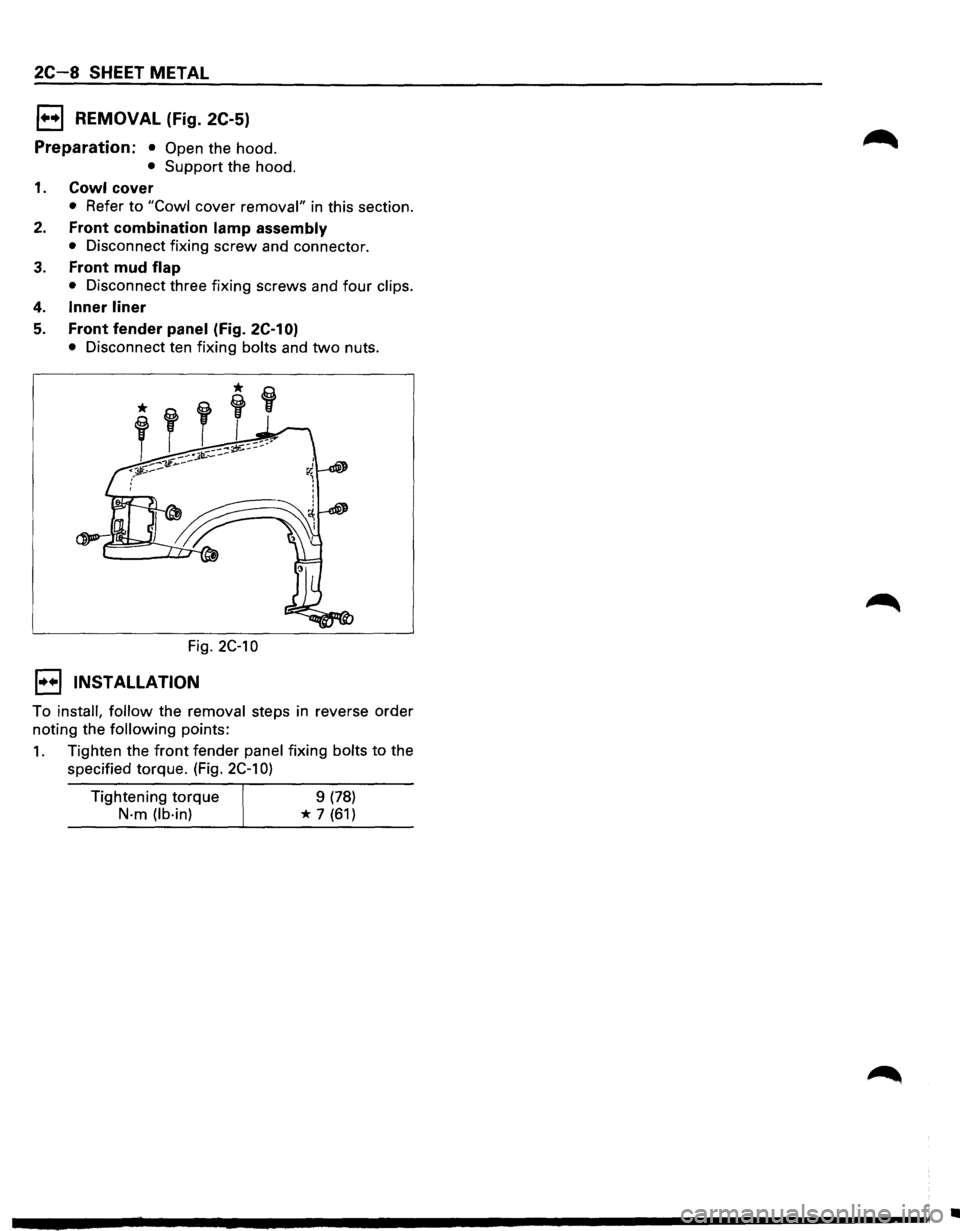
1••1 REMOVAL (Fig. 2C-5)
Preparation: • Open the hood.
• Support the hood.
1. Cowl cover
• Refer to "Cowl cover removal" in this section.
2. Front combination lamp assembly
• Disconnect fixing screw and connector.
3. Front mud flap
•
Disconnect three fixing screws and four clips.
4. Inner liner
5. Front fender panel (fig. 2C-1 0)
• Disconnect ten fixing bolts and two nuts.
Fig.
2C-10
1••1 INSTALLATION
To install, follow the removal steps in reverse order
noting the
following points:
1. Tighten the front fender panel fixing bolts to the
specified torque. (Fig.
2C-1 0)
Tightening torque
N-m (lb·in)
9 (78)
* 7 (61)
•
Page 117 of 1928
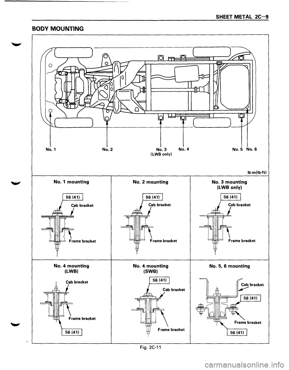
BODY MOUNTING
No.1
No. 1 mounting
No. 4 mounting
(LWB)
Cab bracket
No.2 No.3 No.4 (LWB
only)
No. 2 mounting
No. 4 mounting
(SWB)
Frame bracket
Fig. 2C-11
SHEET METAL 2C-9
No.5 No.6
No. 3 mounting
(LWB only)
N·mUb·ft)
No. 5, 6 mounting
Page 118 of 1928
2C-1 0 SHEET METAL
BODY MOUNTING
1++1 REMOVAL (No. 1 -No. 2)
Preparation:
1. Remove the front bumper.
2. Jack up the vehicle by the frame.
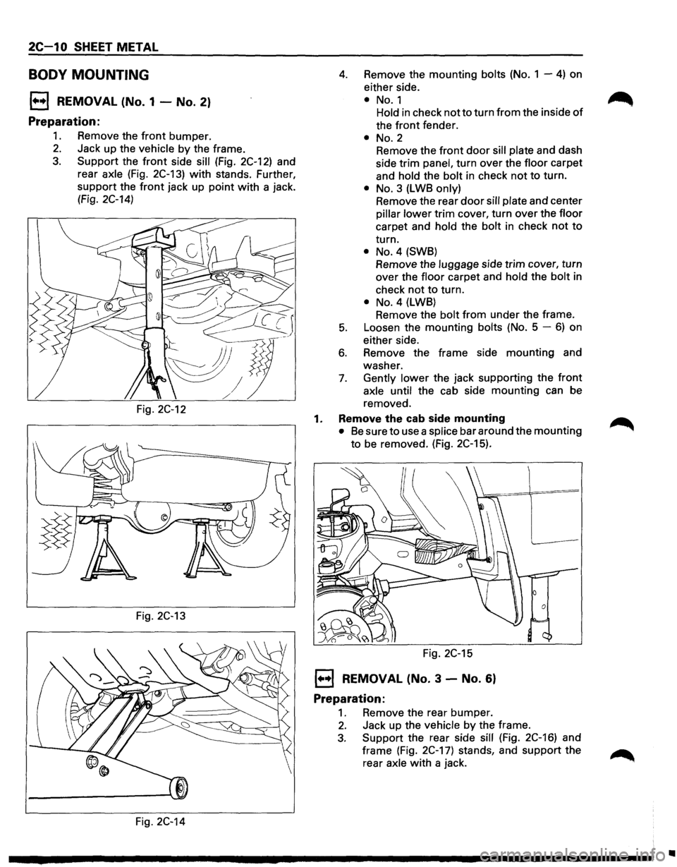
3. Support the front side sill (Fig. 2C-12) and
rear
axle (Fig. 2C-13) with stands. Further,
support the
front jack up point with a jack.
(Fig.
2C-14)
Fig. 2C-12
Fig. 2C-13
Fig. 2C-14
4. Remove the mounting bolts (No. 1 -4) on
either side.
• No.1
Hold in check not to turn from the inside of
the front fender.
• No.2
Remove the front door sill plate and dash
side
trim panel, turn over the floor carpet
and
hold the bolt in check not to turn.
• No. 3 (LWB only)
Remove the rear door sill plate and center
pillar lower trim cover, turn over the floor
carpet and hold the bolt in check not to
turn.
• No.4 (SWB)
Remove the luggage side trim cover, turn
over the
floor carpet and hold the bolt in
check
not to turn.
• No.4 (LWB)
Remove the
bolt from under the frame.
5. Loosen the mounting bolts (No. 5 -6) on
either side.
6. Remove the frame side mounting and
washer.
7. Gently lower the jack supporting the front
axle until the cab side mounting can be
removed.
1. Remove the cab side mounting
• Be sure to use a splice bar around the mounting
to be removed. (Fig. 2C-15).
Fig. 2C-15
1++1 REMOVAL (No. 3 -No. 6)
Preparation:
1. Remove the rear bumper.
2. Jack up the vehicle by the frame.
3. Support the rear side sill (Fig. 2C-16) and
frame (Fig. 2C-17) stands, and support the
rear
axle with a jack.
•
Page 119 of 1928
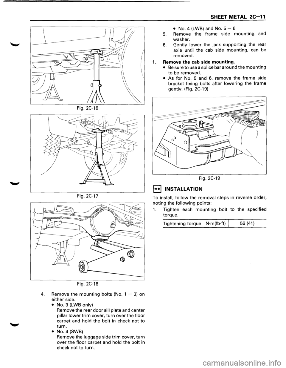
Fig. 2C-16
Fig. 2C-17
Fig. 2C-18
4. Remove the mounting bolts (No. 1 -3) on
either side.
• No. 3 (LWB only)
Remove the rear door sill plate and center
pillar lower trim cover, turn over the floor
carpet and hold the bolt in check not to
turn.
• No.4 (SWB)
Remove the
luggage side trim cover, turn
over the floor carpet and hold the bolt in
check
not to turn.
SHEET METAL 2C-11
• No. 4 (LWB) and No. 5-6
5. Remove the frame side mounting and
washer.
6. Gently lower the jack supporting the rear
axle until the cab side mounting, can be
removed.
1. Remove the cab side mounting.
• Be sure to use a splice bar around the mounting
to be removed.
• As for No. 5 and 6, remove the frame side
bracket fixing
bolts after lowering the frame
gently. (Fig. 2C-19)
Fig. 2C-19
1••1 INSTALLATION
To install, follow the removal steps in reverse order,
noting the
following points:
1. Tighten each mounting bolt to the specified
torque.
Tightening torque
N·m(lb·ft) I 56 (41)
Page 120 of 1928
MEMO
•