battery ISUZU TROOPER 1995 Workshop Manual
[x] Cancel search | Manufacturer: ISUZU, Model Year: 1995, Model line: TROOPER, Model: ISUZU TROOPER 1995Pages: 1928
Page 660 of 1928
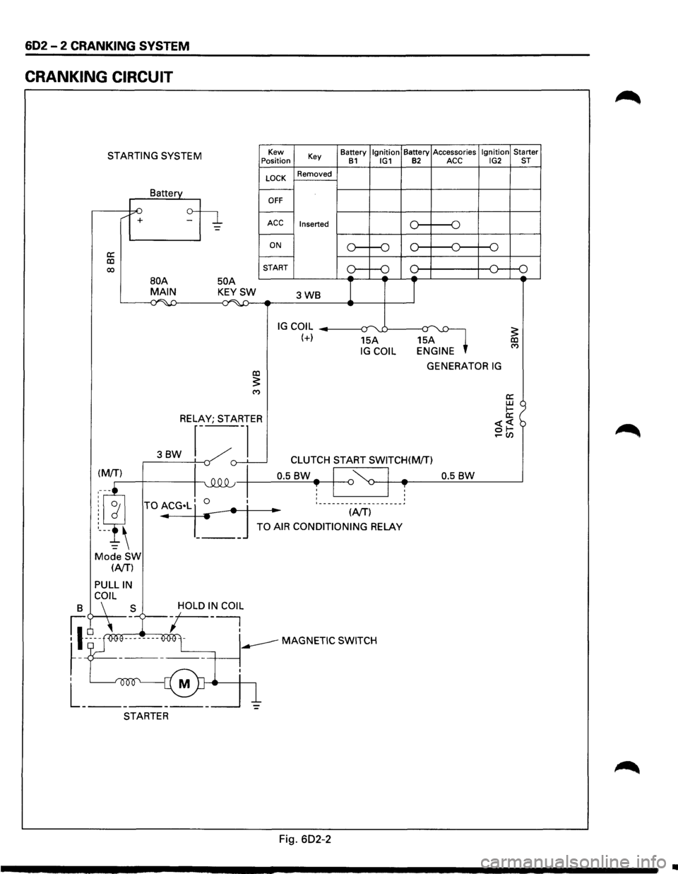
602 - 2 CRANKING SYSTEM
CRANKING CIRCUIT
STARTING SYSTEM
a: co 00
/ +
Battery
50 A
Kew
Position
LOCK
OFF
Key
Removed
ACC Inserted
ON
START Battery
Ignition Battery
Accessories Ignition Starter B1 IG1 B2 ACC IG2 ST
o----o
o----o
oc l---+----+--<0---o
BOA MAIN KEYSW 3WB I I ~~ ...;~-4:) -
IG COIL --------1~-:r uJ----a~ (+) 15A 15A IG COIL ENGINE
GENERATOR IG co :5: ('f)
RELAY; STARTER
3BW r---~
._,()-.L___j -v CLUTCH START SWITCH(M/T)
0.5
BW-I '~ I -0.5 BW ~-+-4~--~~~------~ T I ~ I T : ___________________ ~
.. (NT)
TO AIR CONDITIONING RELAY
Mode SW (NT)
PULLIN
B C\~L _S -/OLD I~ COl~
fl-~ooe--------O<>Ol -----MAGNETIC SWITCH
~-T ------+-----~.
I M
L _______ _
STARTER
Fig. 602-2
•
Page 661 of 1928
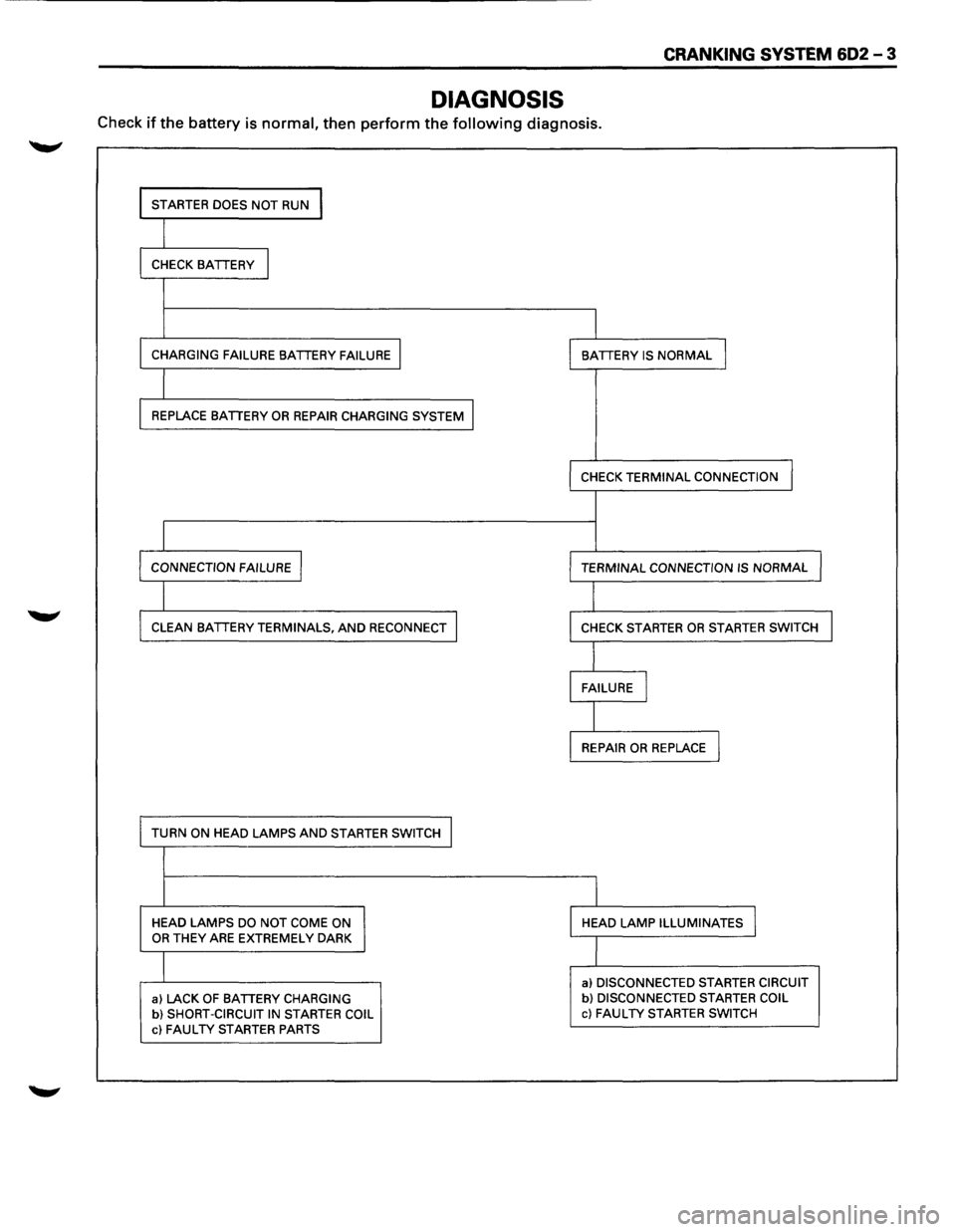
CRANKING SYSTEM 602 -3
DIAGNOSIS
Check if the battery is normal, then perform the following diagnosis.
I STARTER DOES NOT RUN I
I CHECK BATTERY I
I
CHARGING FAILURE BATTERY FAILURE I I BATTERY IS NORMAL I
I REPLACE BATTERY OR REPAIR CHARGING SYSTEM I
I
CHECK TERMINAL CONNECTION
I CONNECTION FAILURE I I TERMINAL CONNECTION IS NORMAL J
I CLEAN BATTERY TERMINALS, AND RECONNECT I
I CHECK STARTER OR STARTER SWITCH I
I FAILURE I
I REPAIR OR REPLACE I
TURN ON HEAD LAMPS AND STARTER SWITCH I
I
HEAD LAMPS DO NOT COME ON HEAD LAMP ILLUMINATES I OR THEY ARE EXTREMELY DARK
I
a) DISCONNECTED STARTER CIRCUIT
a) LACK OF BATTERY CHARGING b) DISCONNECTED STARTER COIL
b) SHORT-CIRCUIT IN STARTER COIL c) FAULTY STARTER SWITCH
c) FAULTY STARTER PARTS
Page 662 of 1928
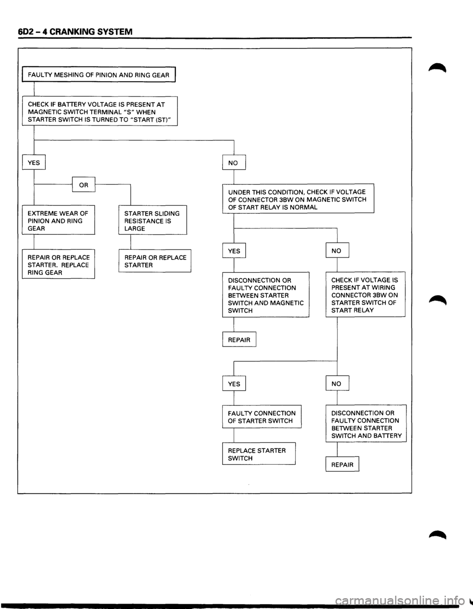
602 - 4 CRANKING SYSTEM
FAULTY MESHING OF PINION AND RING GEAR I
CHECK IF BATTERY VOLTAGE IS PRESENT AT MAGNETIC SWITCH TERMINAL "S" WHEN STARTER SWITCH IS TURNED TO "START (ST)"
YES
I NO I
I OR I I
I
UNDER THIS CONDITION, CHECK IF VOLTAGE OF CONNECTOR 3BW ON MAGNETIC SWITCH
OF START RELAY IS NORMAL EXTREME WEAR OF STARTER SLIDING
PINION AND RING RESISTANCE IS GEAR LARGE
I
I YES I NO I REPAIR OR REPLACE REPAIR OR REPLACE STARTER. REPLACE STARTER
RING GEAR
DISCONNECTION OR CHECK IF VOLTAGE IS
FAULTY CONNECTION PRESENT AT WIRING
BETWEEN STARTER
CONNECTOR 3BW ON
SWITCH
AND MAGNETIC STARTER
SWITCH OF
SWITCH START RELAY
REPAIR I
YES I NO I
FAULTY CONNECTION
DISCONNECTION OR
OF STARTER
SWITCH FAULTY CONNECTION BETWEEN STARTER
SWITCH AND BATTERY
REPLACE
STARTER
I SWITCH REPAIR l
Page 663 of 1928
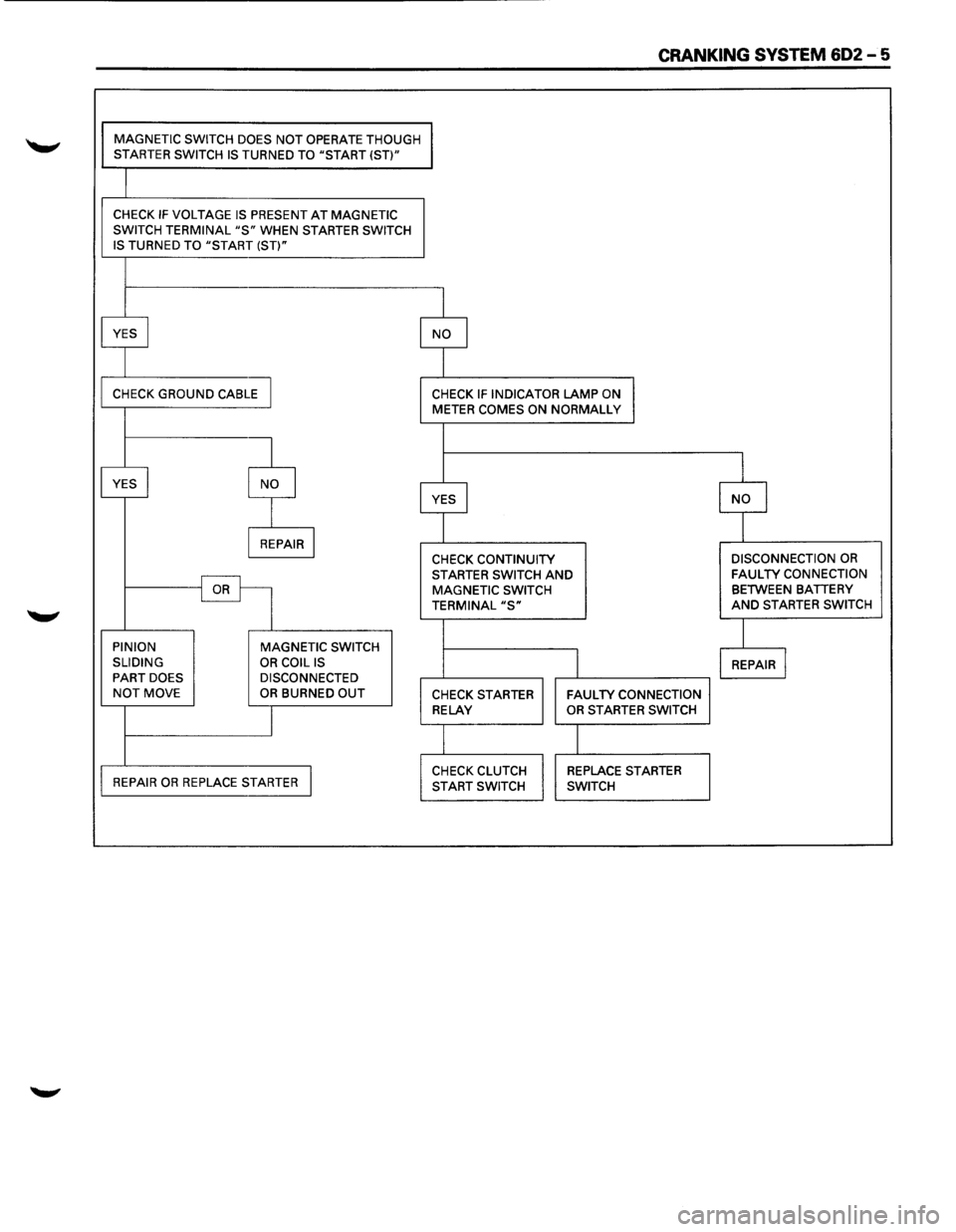
CRANKING SYSTEM 602-5
MAGNETIC SWITCH DOES NOT OPERATE THOUGH STARTER SWITCH IS TURNED TO "START (ST)"
CHECK IF VOLTAGE IS PRESENT AT MAGNETIC
SWITCH TERMINAL "S" WHEN STARTER SWITCH
IS TURNED TO "START (ST)"
YES
I NO I
CHECK GROUND CABLE I CHECK IF INDICATOR LAMP ON METER COMES ON NORMALLY
I
I
YES I NO I YES I I I
NO
I REPAIR I CHECK CONTINUITY DISCONNECTION OR
STARTER SWITCH AND FAULTY CONNECTION
OR MAGNETIC
SWITCH BETWEEN BATTERY
TERMINAL "S" AND STARTER SWITCH
I PINION
MAGNETIC SWITCH
SLIDING
OR COIL IS I REPAIR I PART DOES DISCONNECTED NOT MOVE OR BURNED OUT CHECK STARTER FAULTY CONNECTION
I
RELAY OR STARTER SWITCH
I
REPAIR OR REPLACE STARTER I CHECK CLUTCH REPLACE STARTER
START SWITCH SWITCH
Page 665 of 1928
CRANKING SYSTEM 602 -7
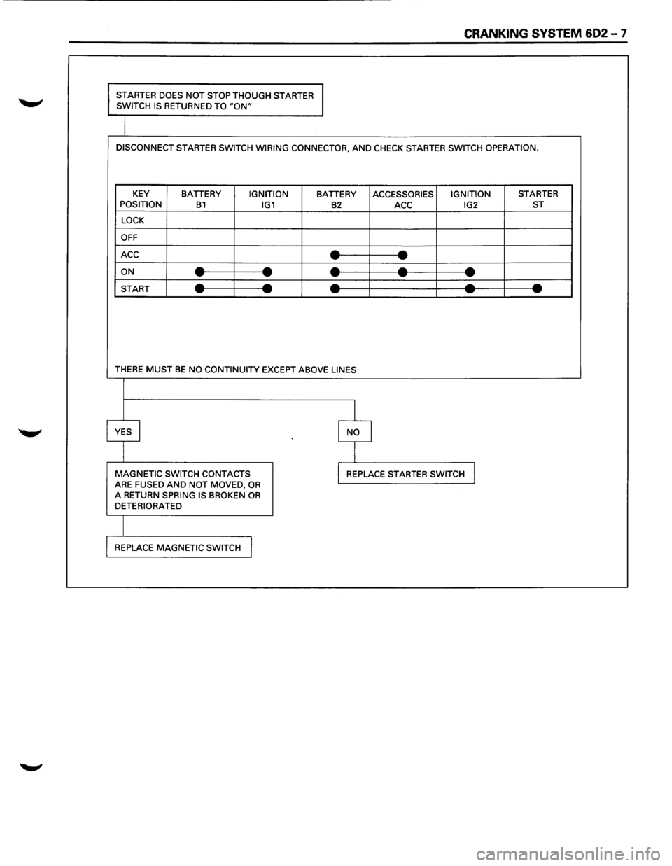
STARTER DOES NOT STOP THOUGH STARTER
SWITCH IS RETURNED TO "ON"
DISCONNECT STARTER SWITCH WIRING CONNECTOR, AND CHECK STARTER SWITCH OPERATION.
KEY
BATTERY IGNITION BATTERY ACCESSORIES IGNITION STARTER
POSITION B1 IG1 B2 ACC IG2 ST
LOCK
OFF
ACC
--- -ON ----------START ----------
THERE MUST BE NO CONTINUITY EXCEPT ABOVE LINES
I
YES I I NO
I
MAGNETIC SWITCH CONTACTS I REPLACE STARTER SWITCH J ARE FUSED AND NOT MOVED, OR A RETURN SPRING IS BROKEN OR DETERIORATED
REPLACE
MAGNETIC SWITCH I
Page 666 of 1928
602-8 CRANKING SYSTEM
ON-VEHICLE SERVICE
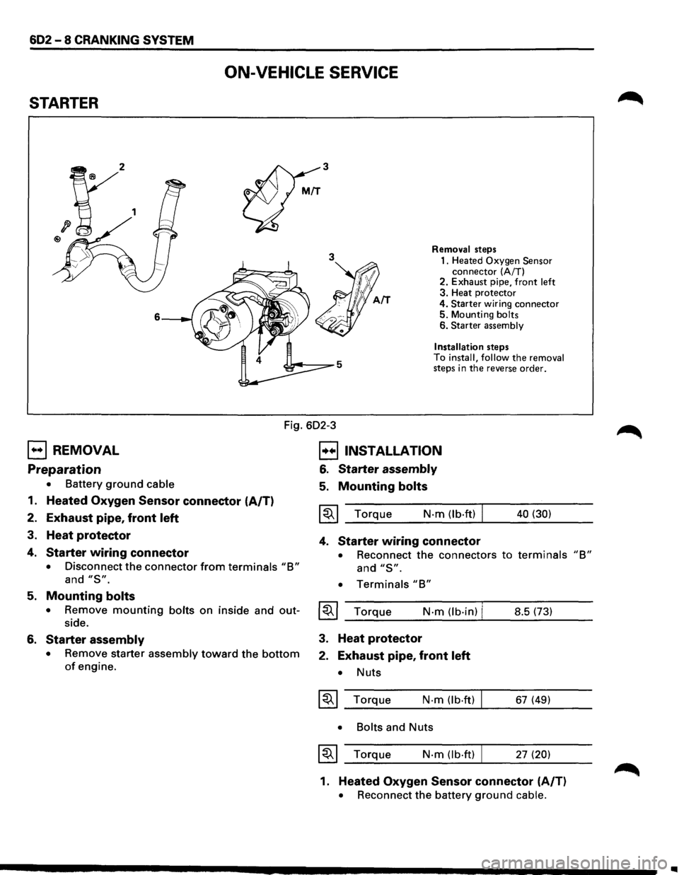
STARTER
3
3
6
Removal steps
1. Heated
Oxygen Sensor connector (A/T)
2. Exhaust pipe, front left 3. Heat protector
4.
Starter wiring connector 5. Mounting bolts 6. Starter assembly
Installation
steps
To install, follow the removal steps in the reverse order.
Fig. 602-3
EJ REMOVAL
Preparation
• Battery ground cable
1. Heated Oxygen Sensor connector (A/T)
2. Exhaust pipe, front left
3. Heat protector
4. Starter wiring connector
• Disconnect the connector from terminals "B"
and "S".
B INSTALLATION
6. Starter assembly
5. Mounting bolts
~~~ Torque N·m (lb·ft) I
4. Starter wiring connector
40 (30)
• Reconnect the connectors to terminals "B"
and "S".
• Terminals "B"
5. Mounting bolts
• Remove mounting bolts on inside and out-~~~ Torque N·m (lb·in) I side. __ _;_ ______ -J.... ______ _ 8.5 (73)
6. Starter assembly
• Remove starter assembly toward the bottom
of engine.
3. Heat protector
2. Exhaust pipe, front left
• Nuts
~~~ Torque N·m (lb.ft)
• Bolts
and Nuts
~~~ Torque N·m (lb·ft) I
67 (49)
27
(20)
1. Heated Oxygen Sensor connector (A/T)
• Reconnect the battery ground cable.
..
Page 674 of 1928
602 -16 CRANKING SYSTEM
l•!•l REASSEMBL V
To install, follow the removal steps in the reverse
order,
noting the following points:
l<:::~ol Grease application places
• Bushing in rear cover and center bracket
• Gears in reduction gear
• Shift lever operating portion
• Sliding portion of pinion
• Plunger sliding portion of magnetic switch
Reassembling Yoke Assembly
Before reassembly, make sure that no metallic
parts attach to the yoke assembly. Because of
strong magnetic force, hold the yoke assembly
and insert it slowly into the armature.
@J TORQUE
Torque for each part (See page 602-18)
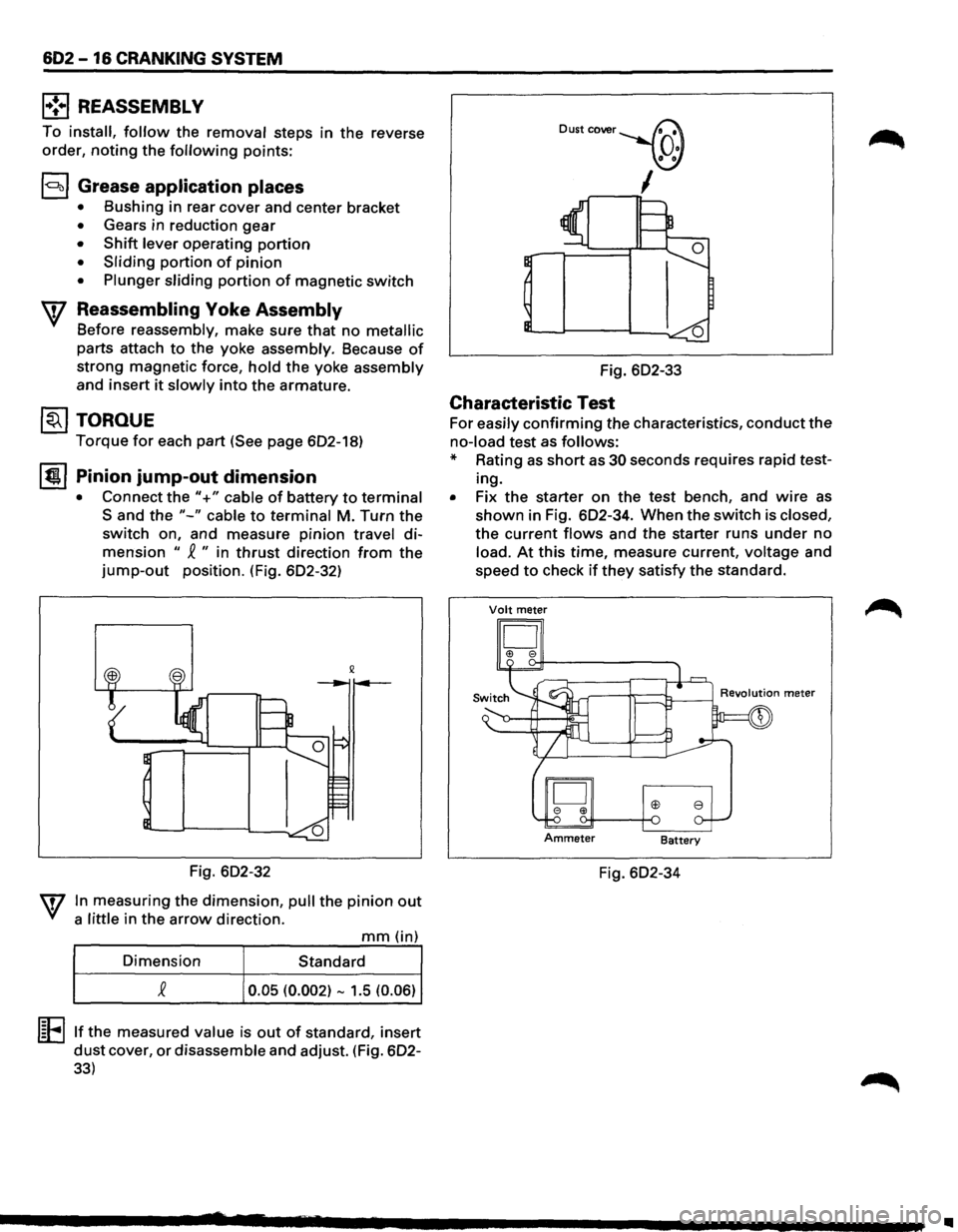
It!!!. I Pinion jump-out dimension
• Connect the"+" cable of battery to terminal
Sand the "-" cable to terminal M. Turn the
switch on, and measure pinion travel di
mension " ~ " in thrust direction from the
jump-out position. (Fig. 602-32)
Fig. 602-32
In measuring the dimension, pull the pinion out
a little in the arrow direction.
mm (in)
Dimension Standard
0.05 (0.002) -1.5 (0.06)
l~Ellf the measured value is out of standard, insert
dust cover, or disassemble and adjust. (Fig. 602-
33)
Dust cover~
_\(J)
,----,1
Fig. 602-33
Characteristic Test
For easily confirming the characteristics, conduct the
no-load test as follows:
* Rating as short as 30 seconds requires rapid test
ing.
• Fix the starter on the test bench, and wire as
shown in Fig. 602-34. When the switch is closed,
the current flows and the starter runs under no
load. At this time, measure current, voltage and
speed
to check if they satisfy the standard.
Volt meter
D I!> e
Fig. 602-34
..
Page 678 of 1928
603-2 CHARGING SYSTEM
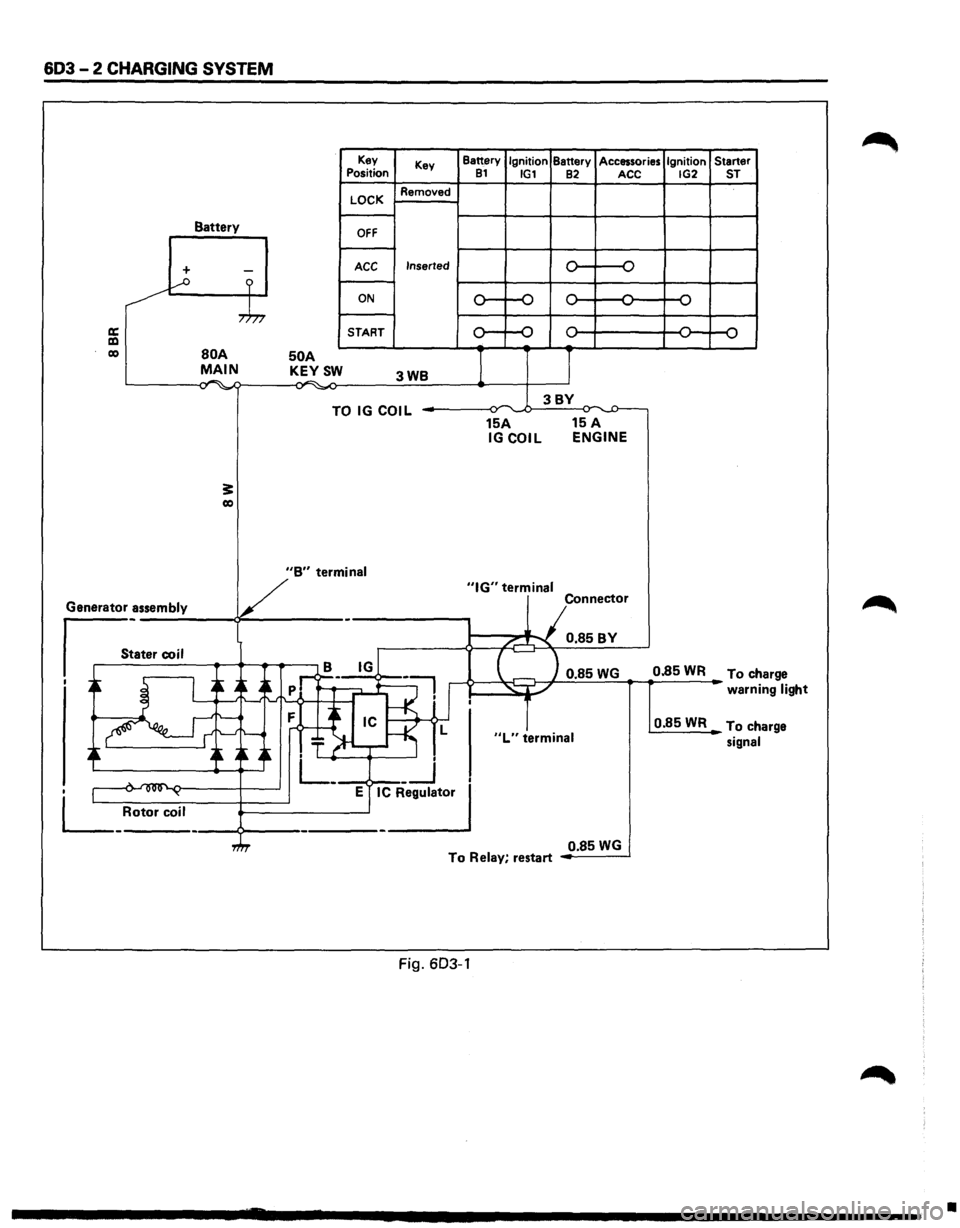
Battery
+ -...--o ?
,.h,
a: a:l co BOA MAIN . .-. -,., ~
3: co
50 A KEYSW
Key
Position
LOCK
OFF
ACC
ON
START Key
Removed
Inserted
3WB
TO IG COIL
Battery Ignition Battery Accessories Ignition Starter 81 IG1 82 ACC IG2 ST
0 -o
,.... ,....
,.... ,... ,.... ...., ...., ...., ...., ....,
0 ,.... ,.... ,.... 0 ....,
...., ....,
I J
3BY ~ ,.,.
15A 15 A IGCOIL ENGINE
V
"B" termin_a_I _____ _,"IG" terminal
Generator assembly
s_:a_t_er_co __ i_l __ ~~~.-.-~ - Connector
/...-"""\. 0.85BY
B IG
I ~ I ~ A~
-~ ..->--~~ 0.85 WG 0.85 WR To ch arge
' _-: .~:f--<·1'
.~ ~ ~~~~ T ~-r-~ L
. L_ __j
• 1 .... ~ ~ E IC Regulator
L_ Rotor coil ----9---------------'
"L" terminal
warni ng light
0.85WR To ch arge
signal
0.85
WG To Relay, restart
Fig. 603-1
•
Page 679 of 1928
CHARGING SYSTEM 603 -3
DIAGNOSIS
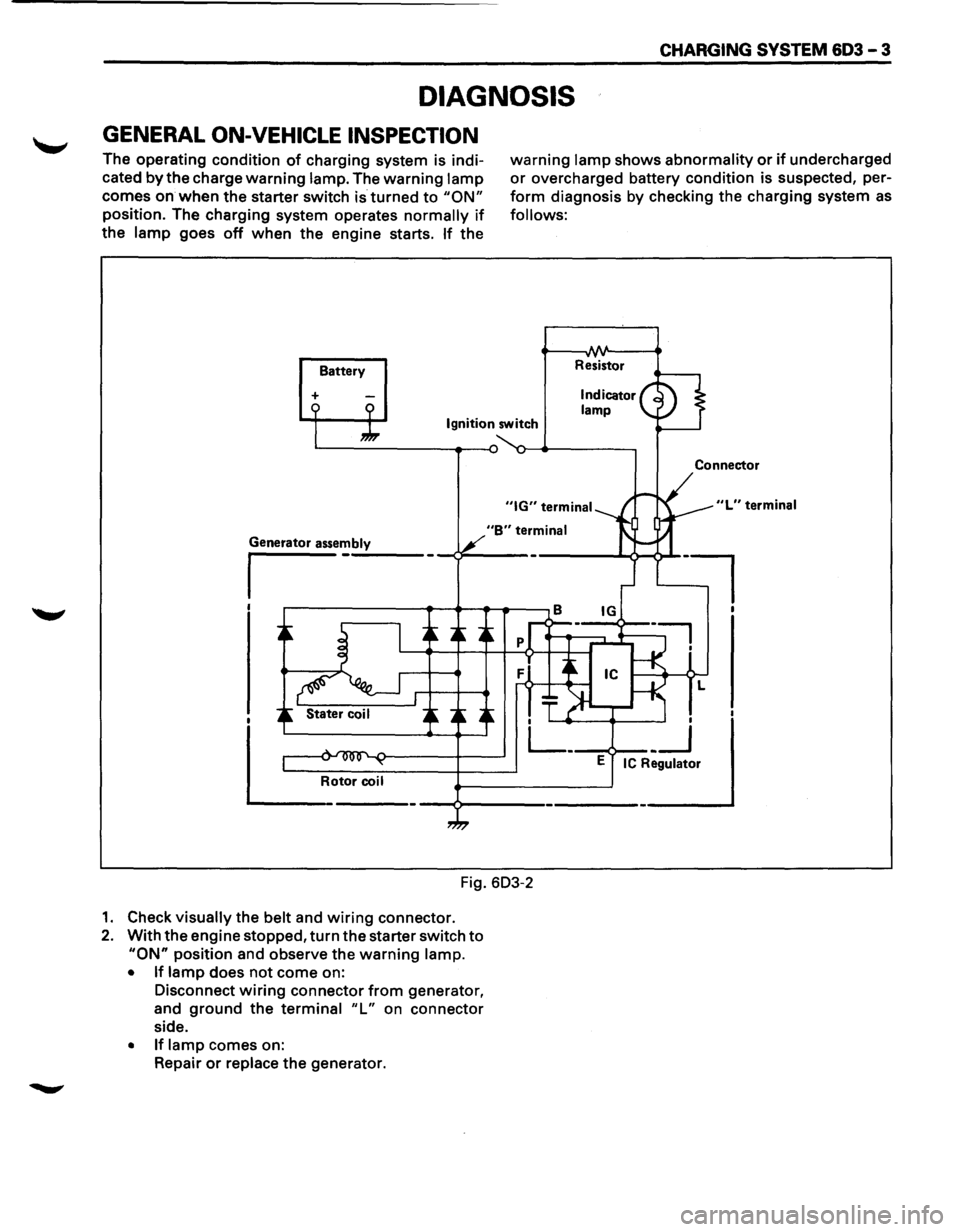
GENERAL ON-VEHICLE INSPECTION
The operating condition of charging system is indi
cated
by the charge warning lamp. The warning lamp
comes on when the starter switch is turned to "ON"
position. The charging system operates normally if
the lamp goes off when the engine starts. If the
Battery
+
warning lamp shows abnormality or if undercharged
or overcharged battery condition is suspected, per
form diagnosis by checking the charging system as
follows:
Resistor
Ignition switch
"B" terminal
Fig. 603-2
1. Check visually the belt and wiring connector.
2. With the engine stopped, turn the starter switch to
"ON" position and observe the warning lamp.
• If lamp does not come on:
Disconnect
wiring connector from generator,
and
ground the terminal "L" on connector
side.
• If lamp comes on:
Repair
or replace the generator.
Connector
"L" terminal
l
Page 680 of 1928
603 - 4 CHARGING SYSTEM
ON-VEHICLE SERVICE
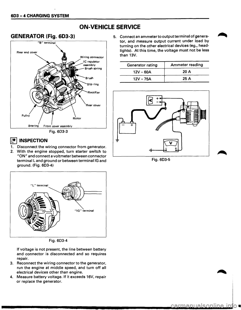
GENERATOR (fig. 603-3}
"B" terminal
Pullry
Fig. 603-3
~ INSPECTION
Wiring connector
I C regulator
assembly
Brush spring
ifier
Rear cover
1. Disconnect the wiring connector from generator.
2. With the engine stopped, turn starter switch to
"ON" and connect a voltmeter between connector
terminal Land ground or between terminaiiG and
ground. (Fig. 603-4)
"IG" terminal
Fig. 603-4
If voltage is not present, the line between battery
and
connector is disconnected and so requires
repair.
3. Reconnect the wiring connector to the generator,
run the
engine at middle speed, and turn off all
electrical
devices other than engine.
4. Measure battery voltage. If it exceeds 16V, repair
or replace the generator.
5. Connect an ammeter to outputterminal of genera
tor, and measure output current under load by
turning on the other electrical devices (eg., head
lights). At this time, the voltage must not be less
than 13V.
Generator rating
Ammeter reading
12V-60A 20A
12V -75A 25A
Fig. 603-5
•