key ISUZU TROOPER 1995 Manual Online
[x] Cancel search | Manufacturer: ISUZU, Model Year: 1995, Model line: TROOPER, Model: ISUZU TROOPER 1995Pages: 1928
Page 1029 of 1928
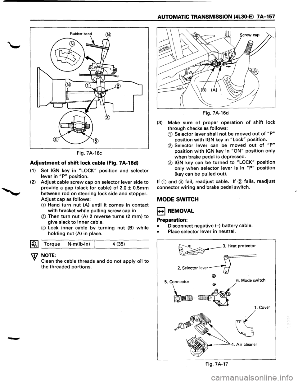
Rubber band
Fig. 7A-16c
Adjustment of shift lock cable (Fig. 7A-16d)
(1) Set IGN key in "LOCK" position and selector
lever
in "P" position.
(2)
Adjust cable screw cap on selector lever side to
provide a gap (slack for cable) of 2.0 ± O.Smm
between rod on steering lock side and stopper.
Adjust cap as follows:
CD Hand turn nut (A) until it comes in contact
with bracket while pulling screw cap in
® Then turn nut (A) 2 reverse turns (2 mm) to
give slack to inner cable.
@ Lock inner cable by turning nut (8) while
holding nut (A) in place.
~~~ Torque N-m(lb-in) j 4 (35)
W NOTE:
Clean the cable threads and do not apply oil to
the threaded portions.
AUTOMATIC TRANSMISSION (4L30·E) 7A-157
Fig. 7A-16d
(3) Make sure of proper operation of shift lock
through checks as follows:
CD Selector lever shall not be moved out of "P"
position with IGN key in "Lock" position.
® Selector lever can be moved out of "P"
position with IGN key in "ON" position only
when brake pedal is depressed.
@ IGN key can be turned to "LOCK" position
only when selector lever is in "P" position
(key can be
pulled out).
If CD and @ fail, readjust cable. If ® fails, readjust
connector
wiring and brake pedal switch.
MODE SWITCH
1++1 REMOVAL
Preparation:
• Disconnect negative (-) battery cable.
• Place selector lever
in neutral.
~3. Heat protector
2. Selector lever
6. Mode switch
1. Cover
~
Fig. 7A-17
Page 1180 of 1928
7D-22 TRANSFER CASE
Inspect the components for the following:
• Teeth for wear, scuffs, nicks, burrs or breaks.
• Keys and springs for wear, cracks or distortion,
replace
if these conditions are present.
• If scuffed, 'nicked or burred conditions cannot be
corrected with a soft stone or crocus cloth,
replace the component.
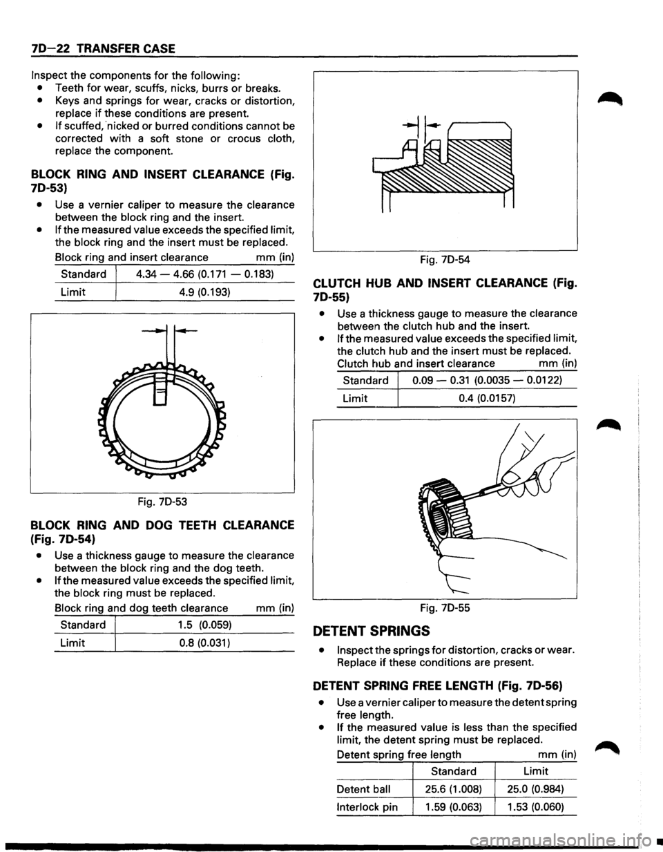
BLOCK RING AND INSERT CLEARANCE (Fig.
7D-53)
• Use a vernier caliper to measure the clearance
between the block ring and the insert.
• If the measured value exceeds the specified limit,
the block ring and the insert
must be replaced.
Block ring and insert clearance
mm (in)
Standard
4.34-4.66 (0.171 - 0.183)
Limit 4.9 (0.193)
Fig. 7D-53
BLOCK RING AND DOG TEETH CLEARANCE
(Fig. 7D-54)
• Use a thickness gauge to measure the clearance
between the block ring and the dog teeth.
• If the measured value exceeds the specified limit,
the block ring
must be replaced. Fig.
7D-54
CLUTCH HUB AND INSERT CLEARANCE (Fig.
7D-55)
• Use a thickness gauge to measure the clearance
between the clutch hub and the insert.
• If the measured value exceeds the specified limit,
the
clutch hub and the insert must be replaced.
Clutch hub and insert clearance
mm (in)
Standard 0.09 -
0.31 (0.0035 -0.0122)
Limit 0.4 (0.0157)
Block ring and dog teeth clearance
mm (in) Fig. 7D-55 ------~~--~------------------~ Standard 1.5 (0.059)
Limit 0.8
(0.031) DETENT SPRINGS
• Inspect the springs for distortion, cracks or wear.
Replace
if these conditions are present.
DETENT SPRING FREE LENGTH (Fig. 7D-56)
• Use a vernier caliper to measure the detent spring
free length.
• If the measured value is less than the specified
limit, the detent spring
must be replaced.
Detent spring free length
mm (in)
Standard Limit
Detent ball 25.6
(1.008) 25.0 (0.984)
Interlock pin 1.59 (0.063) 1.53
(0.060)
•
Page 1186 of 1928
70-28 TRANSFER CASE
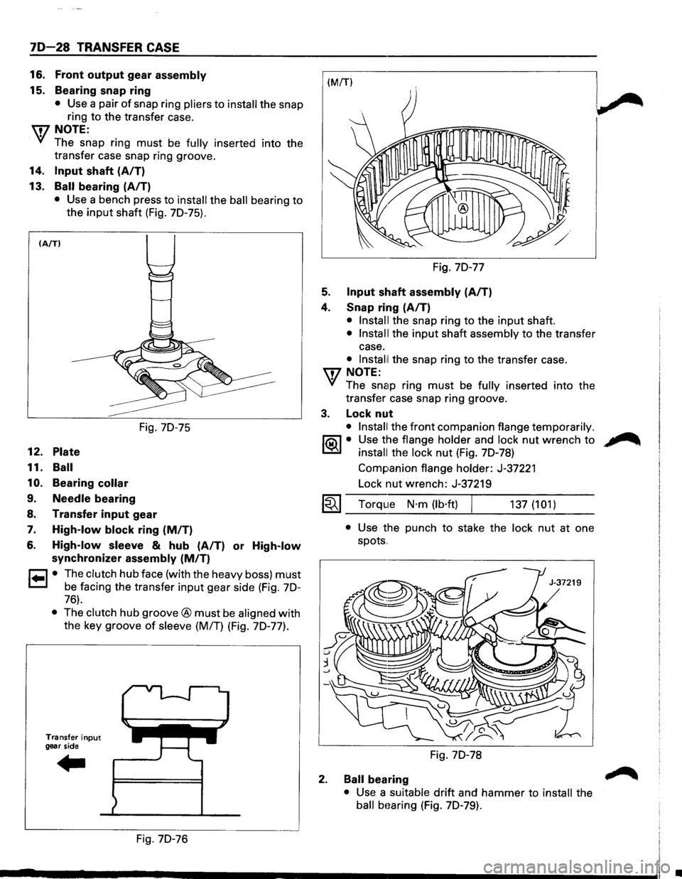
16. Front output gear assembly
15. Bearing snap ring
• Use a pair of snap ring pliers to install the snap
ring to the transfer case.
U7NOTE:
VI The snap ring must be fully inserted into the
transfer case snap ring groove.
14. Input shaft (A/T)
13.
Ball bearing (A/T)
• Use a bench press to install the ball bearing to
the
input shaft (Fig. 70-75).
(A/TI
12. Plate
11. Ball
10.
Bearing collar
9. Needle bearing
Fig. 70-75
8. Transfer input gear
7. High-low block ring (MIT)
6. High-low sleeve & hub (A/T) or High-low
synchronizer assembly (MIT)
r=l • The clutch hub face (with the heavy boss) must
1=.1 be facing the transfer input gear side (Fig. 70-
76).
• The clutch hub groove® must be aligned with
the key groove
of sleeve (M/T) (Fig. 70-77).
Transfer input
gear side
Fig. 70-76 Fig.
70-77
5. Input shaft assembly (AIT)
4. Snap ring (A/T)
• Install the snap ring to the input shaft.
• Install the input shaft assembly to the transfer
case.
• lnstal1l the snap ring to the transfer case.
U7 NOTE:
VI The snap ring must be fully inserted into the
transfer case snap ring groove.
3. Lock nut
• Install the front companion flange temporarily.
1®..1• Use the flange holder and lock nut wrench to
install the lock nut (Fig. 70-78)
Companion
flange holder: J-37221
Lock nut wrench: J-37219
1~1 Torque N·m (lb·ft) 137 (101)
2.
• Use the punch to stake the lock nut at one
spots
..
Fig. 70-78
Ball bearing
• Use a suitable drift and hammer to install the
ball bHaring (Fig. 70-79).
•
Page 1211 of 1928
CHASSIS ELECTRICAL 8-21
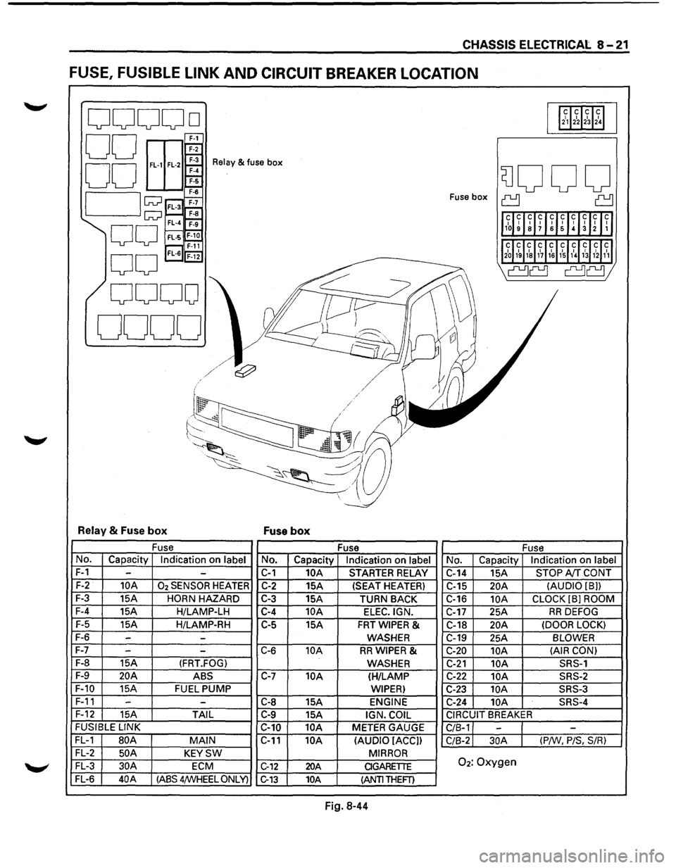
FUSE, FUSIBLE LINK AND CIRCUIT BREAKER LOCATION
ooooo 112~12~1~1~1
00 E
EEr 00 ~
Relay & fuse box
SJOOO 7-6
I lw ;;::;~ Fuse box ~ ~
1l1~~ ~lff~UIH~Inll
w~ F-a FL-4 ~
00 FL·S~ r---, F-11 'l2~J1~ 1~1&11~11~1,\l~31hl1~1
0
0
FL-6 'F-i2
I' ~
\a~ a~;
0000
0000
I ~
l/
~
j
~/~/ e:;?' v II I / / .I / /
('-/ .
~~
-~-~;,a~ ~~ --.:_
~~~~ -
Relay & Fuse box Fuse box
Fuse
Fuse Fuse
No. Capacity Indication on label No. Capacity Indication on label No. Capacity Indication on label
F-1 --C-1 10A STARTER RELAY
C-14 15A STOP A!f CONT
F-2 10A 02 SENSOR HEATER C-2 15A (SEAT HEATER)
C-15 20A (AUDIO [8))
F-3
15A HORN HAZARD C-3 15A
TURN BACK C-16 10A CLOCK (8] ROOM
F-4
15A H/LAMP-LH C-4 10A ELEC.IGN. C-17 25A RR DEFOG
F-5
15A H/LAMP-RH C-5
15A FRTWIPER & C-18 20A (DOOR LOCK)
F-6 --WASHER C-19
25A BLOWER
F-7
- -C-6 10A RRWIPER & C-20 10A (AIR
CON)
F-8
15A (FRT.FOG) WASHER C-21 10A SRS-1
F-9 20A ABS C-7 10A (H/LAMP C-22 10A SRS-2
F-10
15A FUEL PUMP WIPER) C-23 lOA SRS-3
F-11 -
-C-8 15A ENGINE C-24 10A SRS-4
F-12
15A TAIL C-9 15A IGN. COIL CIRCUIT BREAKER
FUSIBLE
LINK
C-10 10A METER GAUGE
C/8-1 --FL-1 80A MAIN C-11 10A
(AUDIO IACC])
C/8-2 30A (P/W, P/S, S/R)
FL-2 50 A KEYSW MIRROR
FL-3 30A ECM C-12 20A CIGARETTE 02: Oxygen
FL-6 40A (ASS 4/WHEEL ONLY) C-13 10A (ANTI THEFT)
Fig. 8-44
Page 1212 of 1928
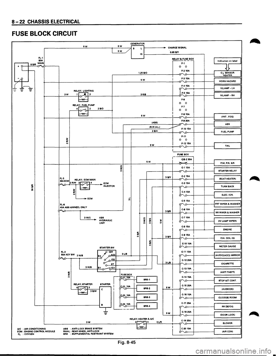
8-22 CHASSIS ELECTRICAL
FUSE BLOCK CIRCUIT
GENERATOR -------------------~s~w~------------~~s~w~--~~~~ r- / B L 1------CHARGE SIGNAL &W _/
FL-1 80A .-----, B 11.'1 MAIN
+ Lt--
l£h
~----/ IG~----------~O~.$~B/V~-----------,
3W REL~HT1NG 1J ---'"~L 3
RELA~PUMP 4 1...---. 12 2 B/0
1.25 B/0
SW
3RJ8
5W
~~~·~ F-1 0 0 F-2 10A
I F-315A
F-8
0 0 F-7 0 0 F-81SA
F-920A
9;nlaool
I
Oz SENSOR HEATER
HORN HAZARD
H/LAMP-LH
H/LAMP-RH
(FRT. FOG)
lABS) -I ABS
I ,--------__:<;;:R·.:.:W.::..Acc·L;;:-1 ____ ----Jv F-10 1SA 2 810
I
~ECM RELAY; ECM MAIN ¢~,...,..J>--+2'-'RIW~_::2~1-o.....-<:>-f-·4.:._ __ _. ~J~CTOR
L...-_.ECM
FL-t 40A ABS 4/WHEEL ONLY
"
.... ...
SW
5W
3 8IY
F-11 0 0 F-1215A
~------' FUSE BOX
CIB-2 30A ~.,.;
C-110A :
C-215A
C-31SA
C-410A
I
J
FUEL PUMP
TAIL
P/W, PIS. SIR
STARTER RELAY
(SEAT HEATER)
TURN BACK
ELEC.IGN.
e-s
15A 1 ""'-.0---t-----+----il FRT WIPER & WASHER
"""' -
I 3W/G
C-810A '---f-+----+.:3.:BIR::::..+---¢""''-£>---i-----f-----jl RR WIPER & WASHER
ABS HYORAULIC UNIT
STARTERSW
FL-2 _JJ OFF
~ ...
..:..AKEYSW 3 W/B ay ' o.N". 3UB
~~--~--~,~------~-0 ~~IG~2Y-----------~ o-: ST 3W/B 81 -.,IG1
FUSE BOX
I
I g1~ 1 J'-:::s:R:s-:1 =I RELAY; STARTER
STARTER I r-
L~---'~-j.t
I I 3UB
sw
C-710A
~';::--~--~-'---~~~HI~LA~M~P~W~IP~E~R~l~~ C-81SA ""'-'>--1---...__---i ENGINE
C-111SA I J~======~l IGN. COIL (G)
C-10 10A
C-1110A
k'-1:>----t----t
~==~I
METER GAUGE
""''-£>---f----------1 (AUDIO[ACC)) MIRROR
C-12 20A
::...1310A I
C-141SA -r"\'-1)----f----t
C-15 20A L,-.
CIGARETTE
(ANTITHEFT)
STOP A/T CONT.
(AUDIO[ B))
C-1810A """"-'-.0---f----------t_j CLOCK[B) ROOM
L---+------------------------iB lt~;_ ~=~~~:~:~::~~~: C-17 2SA I
G1820A
RR DEFOG
= sw (DOOR LOCK) RELAY; HEATER &A/C .:._ __________________ .:.:3~W'-'---------------------~2to~.....-4 3UR C-19 2SA ...... BLOWER
A/C : AIR CONDITIONING ECM : ENGINE CONTIIOL MODULE 0, :OXYGEN ABS
:ANTI-LOCK
BRAKE BYBTEM
RWAL: REAR WHEEL ANTI-LOCK BRB : SUPPLEMENTAL RESTRAINT SYSTEM
C-20 10A (AIR CON)
Fig. 8-45
•
Page 1215 of 1928
CHASSIS ELECTRICAL 8-25
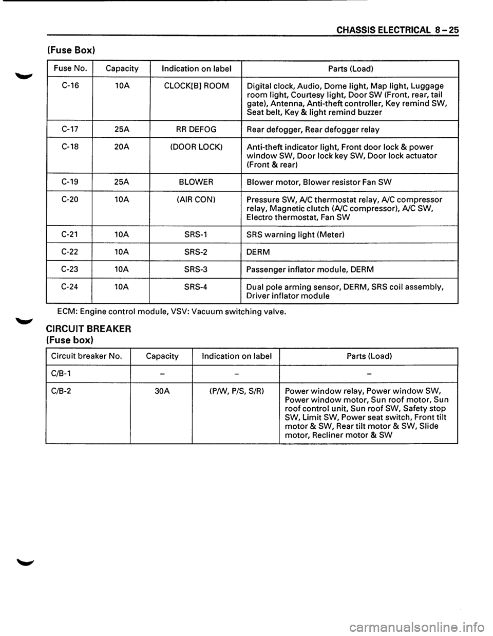
(fuse Box)
Fuse No.
Capacity Indication on label Parts
(Load)
C-16
10A
CLOCK[B] ROOM Digital clock, Audio, Dome light, Map light, Luggage
room light, Courtesy light, Door SW (Front, rear, tail
gate), Antenna, Anti-theft controller, Key remind SW,
Seat belt, Key & light remind buzzer
C-17 25A RR DEFOG Rear defogger, Rear defogger relay
C-18 20A (DOOR LOCK) Anti-theft indicator light, Front door lock & power
window SW, Door lock key SW, Door lock actuator
(Front
& rear)
C-19 25A BLOWER Blower motor, Blower resistor Fan SW
C-20 10A (AIR CON) Pressure SW, A/C thermostat relay, A/C compressor
relay, Magnetic clutch
(A/C compressor), A/C SW,
Electro thermostat, Fan SW
C-21 10A SRS-1 SRS warning light (Meter)
C-22 10A SRS-2 DERM
C-23
10A SRS-3 Passenger inflator module, DERM
C-24
10A SRS-4 Dual pole arming sensor, DERM, SRS coil assembly,
Driver inflator module
ECM: Engine control module, VSV: Vacuum switching valve.
CIRCUIT BREAKER
(fuse box)
Circuit breaker No.
C/B-1
C/B-2
Capacity
-
30A
Indication on label
-
(P/W, P/S, S/R)
Parts (Load)
-
Power window relay, Power window SW,
Power window motor, Sun roof motor, Sun
roof control unit, Sun roof SW, Safety stop
SW, Limit SW, Power seat switch, Front tilt
motor & SW, Rear tilt motor & SW, Slide
motor, Recliner
motor & SW
Page 1216 of 1928
8 -26 CHASSIS ELECTRICAL
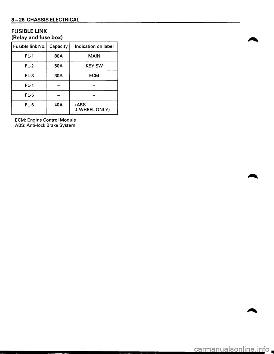
FUSIBLE LINK
(Relay and fuse box)
Fusible link No. Capacity Indication on label
FL-1 BOA MAIN
FL-2 50 A KEYSW
FL-3 30A ECM
FL-4
- -
FL-5 --
FL-6 40A (ABS
4-WHEEL ONLY)
ECM: Engine Control Module
ABS: Anti-lock Brake System
•
Page 1219 of 1928
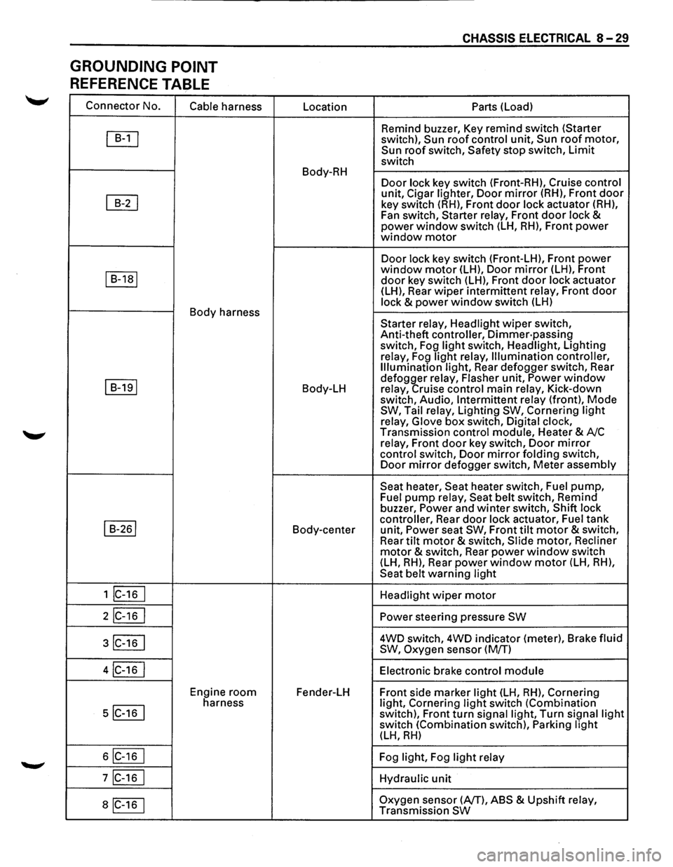
GROUNDING POINT
REFERENCE TABLE
Connector No.
Cable harness
~
~
I B-1a1
Body harness
I B-191
I B-261
1 lc-16 I
2IC-16 I
3IC-16 I
4IC-16 I
Engine room
5IC-16 I
harness
6IC-16 I
7IC-16 I
aiC-16 1
Location
Body-RH
Body-LH
Body-center
Fender-LH
CHASSIS ElECTRICAL 8-29
Parts (Load)
Remind buzzer, Key remind switch (Starter
switch),
Sun roof control unit, Sun roof motor, Sun roof switch, Safety stop switch, Limit
switch
Door lock key switch (Front-RH), Cruise control
unit, Cigar lighter, Door mirror (RH), Front door
key switch (RH), Front door lock actuator (RH),
Fan switch, Starter relay, Front
door lock & power window switch (LH, RH), Front power window motor
Door lock key switch (Front-LH), Front power window motor (LH), Door mirror (LH), Front
door key switch (LH), Front door lock actuator
(LH), Rear wiper intermittent relay, Front door
lock & power window switch (LH)
Starter relay, Headlight
wiper switch,
Anti-theft controller,
Dimmer·passing switch, Fog light switch, Headlight, Lighting
relay, Fog
light relay, Illumination controller,
Illumination light, Rear defogger switch, Rear
defogger relay, Flasher unit,
Power window relay, Cruise control main relay, Kick-down
switch, Audio, Intermittent relay (front), Mode SW, Tail relay, Lighting SW, Cornering light
relay, Glove box switch, Digital clock,
Transmission control module, Heater & A/C
relay, Front
door key switch, Door mirror
control switch, Door mirror folding switch,
Door mirror defogger switch, Meter assembly
Seat heater, Seat heater switch, Fuel pump, Fuel pump relay, Seat belt switch, Remind
buzzer, Power and winter switch, Shift lock
controller, Rear
door lock actuator, Fuel tank
unit, Power seat SW, Front tilt motor & switch,
Rear tilt motor & switch, Slide motor, Recliner
motor & switch, Rear power window switch
(LH, RH), Rear power window motor (LH, RH),
Seat belt warning light
Headlight
wiper motor
Power steering pressure SW
4WD switch, 4WD indicator (meter), Brake fluid
SW, Oxygen sensor (M/T)
Electronic brake control
module
Front side marker light (LH, RH), Cornering
light, Cornering light switch (Combination
switch), Front turn signal light, Turn signal light switch (Combination switch), Parking light (LH, RH)
Fog light, Fog light relay
Hydraulic
unit
Oxygen sensor (AfT), ABS & Upshift relay,
Transmission SW
Page 1220 of 1928
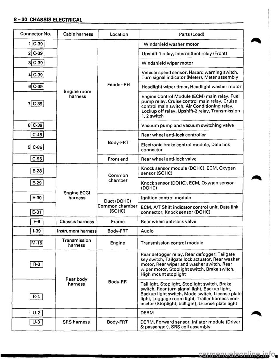
8-30 CHASSIS ELECTRICAL
Connector No.
Cable harness
Location Parts (load)
1jC-39I Windshield washer motor
21 C-391 Upshift-1 relay, Intermittent relay (Front)
31 C-391 Windshield wiper motor
41 C-39j Vehicle speed
sensor, Hazard warning switch,
Turn
signal indicator (Meter), Meter assembly
sl C-391 Fender-RH Headlight wiper timer, Headlight washer motor
Engine room
harness Engine Control Module (ECM)
main relay, Fuel
71 C-391 pump relay, Cruise control main relay, Cruise
control main switch, Air Conditioning relay,
Lockup off relay, Upshift-2 relay, Transmission-
1, 2 switch
al C-391 Vacuum pump and vacuum switching valve
I C-451 Rear wheel anti-lock controller
sl c-asl
Body-FRT Electronic brake control module, Data link
connector
I C-961 Front end Rear wheel
anti-lock valve
I E-281 Knock sEmsor module (DOHC), ECM, Oxygen
Common sensor (SOHC)
I E-291 chamber Knock sensor (DOHC), ECM, Oxygen sensor
(DOHC)
Engine
ECGI
I E-30 I harness Duct (DOHC) Ignition control
module
Common chamber
ECM, AfT Shift indicator control unit, Data link
I
E-311 (SOHC) connector, Knock sensor (DOHC)
~ Chassis harness Frame
Rear wheel anti-lock valve
11-391 Instrument
harness
Body-FRT Audio
IM-161 Transmission
Engine Transmission control module harness
Rear defogger
relay, Rear defogger, Tailgate
~
key switch, Tailgate lock actuator, Rear washer
motor, A:ear wiper and washer switch, Rear
wiper motor, Stoplight switch, Brake switch,
High
mount stoplight
Rear body Body-RR
harness Taillight, Stoplight, Stoplight switch, Brake
switch,
near turn signal light, Backup light,
~
Backup light switch, Mode switch, License plate
light, Lu!;)gage room light, Trailer harness con-
nector
(Stoplight, taillight), License plate light
~ DERM
00 SRS harness Body-FRT
DERM, Forward sensor, Inflator module (Driver
& passenger),
SRS coil assembly
•
Page 1233 of 1928
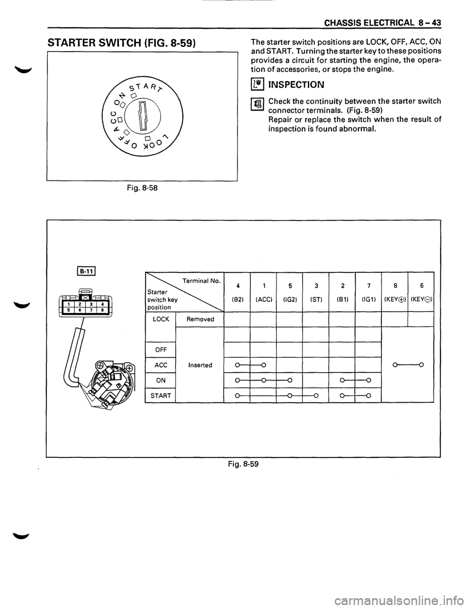
STARTER SWITCH (FIG. 8-59)
Fig. 8-58
~
~
LOCK Removed
OFF
ACC Inserted
ON
START
4
(62)
CHASSIS ELECTRICAL 8-43
The starter switch positions are LOCK, OFF, ACC, ON
and START. Turning the starter key to these positions
provides a circuit
for starting the engine, the opera
tion of accessories, or stops the engine.
~ INSPECTION
1 ~ 1 Check the continuity between the starter switch
connector terminals. (Fig. 8-59)
1
Repair or replace the switch when the result of
inspection is found abnormal.
5 3 2 7 8 6
(ACCl (IG2l (STl (61) (IG1l (KEY(£)) (KEY8l
o----o
Fig.
8-59