key ISUZU TROOPER 1995 Repair Manual
[x] Cancel search | Manufacturer: ISUZU, Model Year: 1995, Model line: TROOPER, Model: ISUZU TROOPER 1995Pages: 1928
Page 761 of 1928
®
DRIVEABILITY AND EMISSIONS 6E2-65
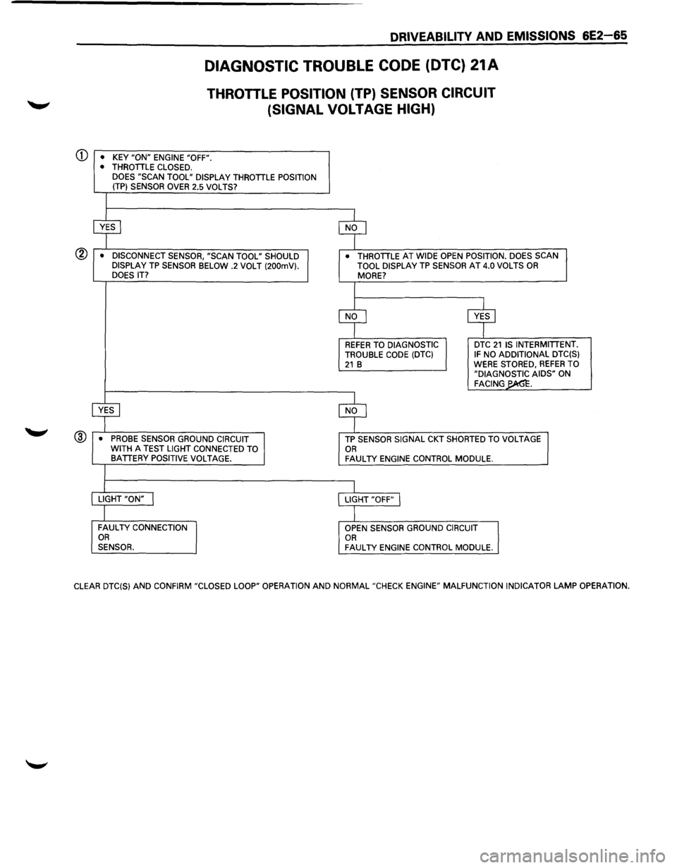
DIAGNOSTIC TROUBLE CODE (DTC) 21A
THROTILE POSITION (TP) SENSOR CIRCUIT
(SIGNAL
VOLTAGE HIGH)
• KEY "ON" ENGINE "OFF". • THROTTLE CLOSED.
DOES "SCAN TOOL" DISPLAY THROTTLE POSITION
(TP) SENSOR OVER 2.5 VOLTS?
$ $
• DISCONNECT SENSOR, "SCAN TOOL" SHOULD • THROTTLE AT WIDE OPEN POSITION. DOES SCAN
DISPLAY TP SENSOR BELOW .2 VOLT (200mV}. TOOL DISPLAY TP SENSOR AT 4.0 VOLTS OR
DOES IT? MORE?
I
$ cvr
REFER TO DIAGNOSTIC DTC 21 IS
INTERMITTENT.
TROUBLE CODE (DTC} IF NO ADDITIONAL DTC(S} 21 B WERE STORED, REFER TO
"DIAGNOSTIC AIDS" ON FACING~.
~ $
• PROBE SENSOR GROUND CIRCUIT TP SENSOR SIGNAL CKT SHORTED TO VOLTAGE
WITH A TEST LIGHT CONNECTED TO OR BATTERY POSITIVE VOLTAGE. FAULTY ENGINE CONTROL MODULE.
I LIGHT "ON" I LIGHT "OFF" I
I FAULTY CONNECTION
OPEN SENSOR GROUND CIRCUIT OR
OR SENSOR. FAULTY ENGINE CONTROL MODULE.
CLEAR DTC(S}
AND CONFIRM "CLOSED LOOP" OPERATION AND NORMAL "CHECK ENGINE" MALFUNCTION INDICATOR LAMP OPERATION.
Page 793 of 1928
DRIVEABILITV AND EMISSIONS 6E2-97
ADDITIONAL CHECKS • CHECK: Intake and exhaust manifold for casting
• CHECK: Exhaust gas recirculation (EGR) gasket flash.
for faulty or loose fit.
• CHECK: EGR operation for being open all the time.
Refer to
"EGR," CHART C-7.
DIESELING, RUN-ON
Definition: Engine continues to run after key is turned
"OFF", but runs very roughly. If engine
runs
smoothly, check ignition switch and
adjustment.
PRELIMINARY CHECKS
• Perform the careful visual/physical checks as
described at start of "Symptoms," Section "6E2-
B."
FUEL SYSTEM
• CHECK: Injectors for leaking. Refer to "Fuel
System Diagnosis" CHART A-7.
Page 814 of 1928
6E2-118 DRIVEABILITV AND EMISSIONS
FUEL METERING SYSTEM COMPONENTS
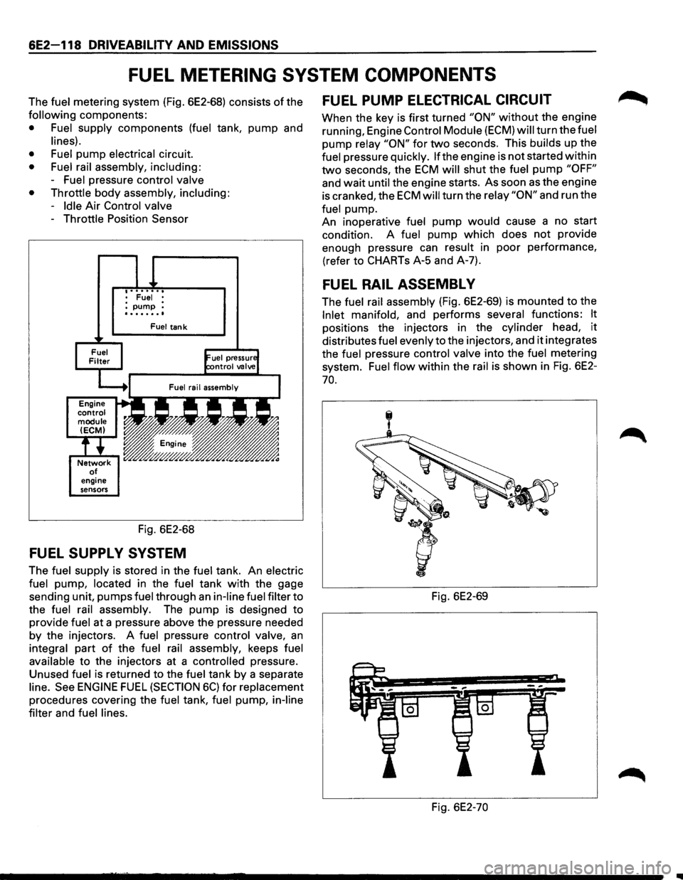
The fuel metering system (Fig. 6E2-68) consists of the
following components:
• Fuel supply components (fuel tank, pump and
lines).
• Fuel
pump electrical circuit.
• Fuel rail assembly, including:
-Fuel pressure control valve
• Throttle
body assembly, including:
-Idle Air Control valve
-Throttle Position Sensor
engine
sensors
• Fuel • :pump : ........
Fuel tank
Fig. 6E2-68
FUEL SUPPL V SYSTEM
The fuel supply is stored in the fuel tank. An electric
fuel
pump, located in the fuel tank with the gage
sending unit, pumps
fuel through an in-line fuel filter to
the
fuel rail assembly. The pump is designed to
provide
fuel at a pressure above the pressure needed
by the injectors. A fuel pressure control valve, an
integral part of the fuel rail assembly, keeps fuel
available
to the injectors at a controlled pressure.
Unused
fuel is returned to the fuel tank by a separate
line. See ENGINE FUEL (SECTION 6C) for replacement
procedures covering the fuel tank, fuel pump, in-line
filter
and fuel lines.
FUEL PUMP ELECTRICAL CIRCUIT
When the key is first turned "ON" without the engine
running, Engine
Control Module (ECM) will turn the fuel
pump relay "ON" for two seconds. This builds up the
fuel pressure quickly. lfthe engine is not started within
two seconds, the ECM will shut the fuel pump "OFF"
and wait until the engine starts. As soon as the engine
is cranked, the
ECM will turn the relay "ON" and run the
fuel pump.
An inoperative
fuel pump would cause a no start
condition. A
fuel pump which does not provide
enough pressure can
result in poor performance,
(refer to CHARTs A-5 and A-7).
FUEL RAIL ASSEMBL V
The fuel rail assembly (Fig. 6E2-69) is mounted to the
Inlet manifold, and performs several functions: It
positions the injectors in the cylinder head, it
distributes fuel evenly to the injectors, and it integrates
the
fuel pressure control valve into the fuel metering
system.
Fuel flow within the rail is shown in Fig. 6E2-
70.
Fig. 6E2-69
Fig. 6E2-70
Page 835 of 1928
RESULTS OF INCORRECT OPERATION
An open or ground in the Ignition Control (I C) or bypass
circuits
will set a Diagnostic Trouble Code (DTC) 42 and
cause the engine
to run on the Ignition Control Module
(ICM)
timing.
The Engine
Control Module (ECM) uses information
from the Intake Air Temperature (IAT) and engine
coolant sensors in addition to revolution per minute
(rpm) to
calculate spark advance as follows:
• Cold
engine -more spark advance.
• Engine under minimum load based on rpm and
low amount of air flow = more spark advance.
• Hot engine = less spark advance.
• Engine under heavy load based on rpm and high
air
flow = less spark advance.
HOW DIAGNOSTIC TROUBLE CODE (DTC)
42 IS DETERMINED
When the system is running on the ICM, that is, no
voltage on the bypass line, the ICM grounds (GND) the
IC signal. The ECM expects to see no voltage on the IC
line during this condition.lf it sees a voltage, it sets DTC
42 and will not go into the IC mode.
DRIVEABILITY AND EMISSIONS 6E2-139
When the rpm for IC is reached (about 400 rpm) the
ECM applies 5 volts to the bypass line and the IC should
no longer be grounded in the ICM so the IC voltage
should
be varying.
An open in the
IC circuit while running, will result in the
engine continuing to run, but in a back-up
ig~it~on
timing mode (module timing) at a calculated t1mmg
value
and the malfunction indicator lamp will not be
"ON".
If
the IC circuit is shorted to GND, the "Check Engine"
malfunction
indicator lamp will be turned "ON", and a
DTC 42 will be set and the engine will operate in
module timing. Either condition may cause poor
performance and reduced
fuel economy.
If the bypass line is open or GND, the ICM will not
switch to IC mode so the IC voltage will be low and DTC
42 will be set.
If the IC line is grounded, the ICM will switch to IC, but
because the line isGNDtherewill be no ICsignai.A DTC
42 will be set.
DIAGNOSIS
If the engine cranks but will not run, CHART A-3 will be
used to determine if the Electronic Ignition (EI) system
is the cause
of the problem or if it is another part of the
fuel injection system.
If DTC 42 is set, that DTC chart should be used for
diagnosis. If no DTC is set and the ignition system is
suspected, use
CHART C4-D ("EI" Misfire) for
diagnosis.
DIAGNOSTIC TROUBLE CODE (DTC) 12
DTC 12 is used during the on-board diagnostic system
check procedure to test the
DTC display ability of the
ECM. This diagnostic trouble code indicates that the
ECM is not receiving the engine speed (REFERENCE)
signal. This occurs with the ignition key "ON" and the
engine not running.
The "reference"
signal also triggers the fuel injection
system.
Without the "reference" signal the engine
cannot run.
ON-VEHICLE SERVICE
ELECTRONIC IGNITION (EI) ASSEMBLY
1••1 REMOVE OR DISCONNECT
1. Negative battery cable
2. "EI" electrical connectors (3)
3. Spark plug wires. (Note wire positions to proper
coils) (6)
4. "EI" assembly to bracket bolts (3)
5. "EI" assembly from Intake Plenum.
1••1 INSTALL OR CONNECT
1. "EI" assembly bracket to Intake Plenum
Tighten bolts to 25 N·m (19 lb·ft)
2. Spark plug wires to correct spark plugs
3. "EI" electrical connectors
4. Negative battery cable
Page 882 of 1928
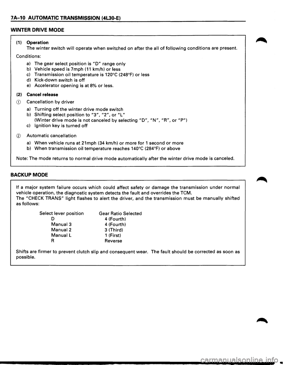
7A-10 AUTOMATIC TRANSMISSION (4L30-E)
WINTER DRIVE MODE
(1) Operation
The winter switch will operate when switched on after the all of following conditions are present.
Conditions:
a) The gear select position is "D" range only
b) Vehicle speed is 7mph (11 km/h) or less
c) Transmission oil temperature is 120°C (248°F) or less
d) Kick-down switch is off
e) Accelerator opening is at 8% or less.
(2) Cancel release
CD Cancellation by driver
a) Turning off the winter drive mode switch
b) Shifting select position to "3", "2", or "L"
(Winter drive mode is not canceled by selecting "D", "N", "R", or "P")
c) Ignition key is turned off
® Automatic cancellation
a) When vehicle runs at 21mph (34 km/h) or more for 1 second or more
b) When transmission oil temperature reaches 140°C (284°F) or above
Note: The mode returns
to normal drive mode automatically after the winter drive mode is canceled.
BACKUP MODE
If a major system failure occurs which could affect safety or damage the transmission under normal
vehicle operation, the diagnostic system detects the fault and overrides the TCM.
The "CHECK TRANS" light flashes to alert the driver, and the transmission must be manually shifted
as follows:
Select lever
position
D
Manual3
Manual2
Manual L
R
Gear Ratio Selected
4 (Fourth)
4 (Fourth)
3 (Third)
1 (First)
Reverse
Shifts are firmer to prevent clutch slip and consequent wear. The fault should be corrected as soon as
possible.
Page 887 of 1928
AUTOMATIC TRANSMISSION (4L30-E) 7A-15
DIAGNOSIS
. .,._., INTRODUCTION
The systematic trouble shooting information covered by this Section offers a practical and systematic
approach
to diagnosing 4L30-E transmission, using information that can be obtained from road tests,
electrical diagnosis, oil pressure checks or noise evaluation.
The key to correcting a complaint is to make use of all of the available symptoms and logically letting them
direct you
to the cause.
When
dealing with automatic transmission complaints, it is best to gather as many symptoms as possible
before making the decision to remove the transmission from the vehicle.
Frequently,
the correction of the cause of the complaint does not require removal of the transmission from
the vehicle.
Page 907 of 1928
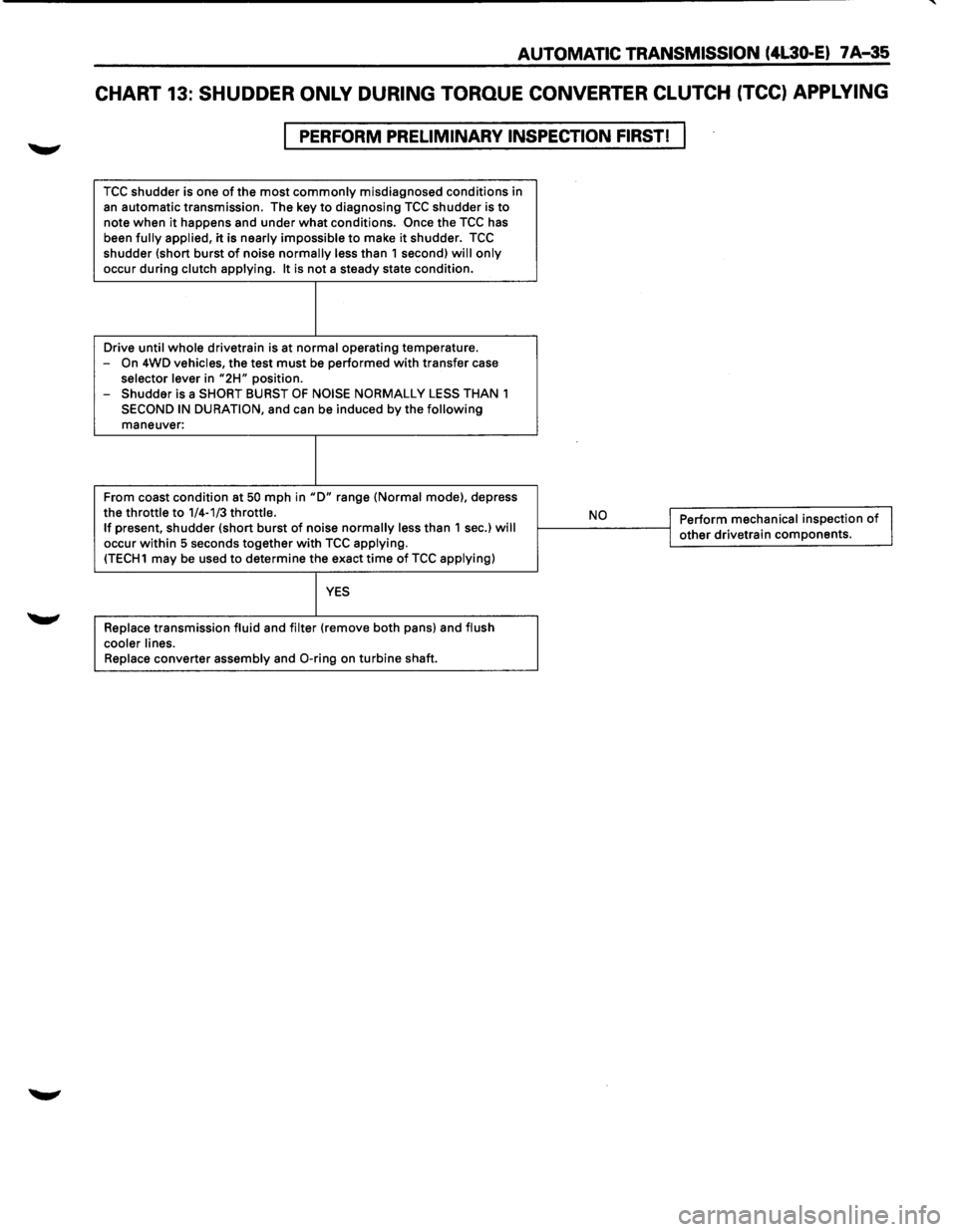
AUTOMATIC TRANSMISSION (4L30-E) 7 A-35
CHART 13: SHUDDER ONLY DURING TORQUE CONVERTER CLUTCH (TCC) APPLYING
PERFORM PRELIMINARY INSPECTION FIRST!
TCC shudder is one of the most commonly misdiagnosed conditions in
an automatic transmission. The key to diagnosing TCC shudder is to note when it happens and under what conditions. Once the TCC has
been fully applied, it is nearly impossible to make it shudder. TCC shudder {short burst of noise normally less than 1 second) will only
occur during clutch applying. It is not a steady state condition.
Drive
until whole drivetrain is at normal operating temperature.
-On 4WD vehicles, the test must be performed with transfer case selector lever in "2H" position.
- Shudder is a SHORT BURST OF NOISE NORMALLY LESS THAN 1
SECOND IN DURATION, and can be induced by the following maneuver:
From coast condition at
50 mph in "D" range {Normal mode), depress
the throttle to 1/4-1/3 throttle. If present, shudder {short burst of noise normally less than 1 sec.) will occur within 5 seconds together with TCC applying. {TECH1 may be used to determine the exact time of TCC applying)
YES
Replace transmission fluid and filter {remove both pans) and flush
cooler lines.
Replace
converter assembly and 0-ring on turbine shaft.
,__ __ N_o ___ ---<1 Perform mechanical inspection of I j other drivetrain components.
Page 917 of 1928
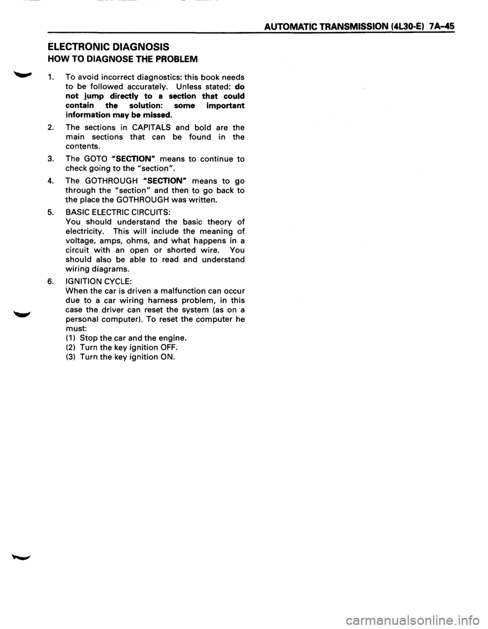
ELECTRONIC DIAGNOSIS
HOW TO DIAGNOSE THE PROBLEM
~ 1. To avoid incorrect diagnostics: this book needs
to be followed accurately. Unless stated: do
not jump
directly to a section that could
contain the solution: some important
information may be missed.
2. The sections in CAPITALS and bold are the
main sections that can be found in the
contents.
3. The GOTO "SECTION" means to continue to
check going to the "section".
4. The GOTHROUGH "SECTION" means to go
through the "section" and then to go back to
the place the GOTHROUGH was written.
5. BASIC ELECTRIC CIRCUITS:
You should understand the basic theory of
electricity. This will include the meaning of
voltage, amps, ohms, and what happens in a
circuit with an open or shorted wire. You
should also be able to read and understand
wiring diagrams.
6. IGNITION CYCLE:
When the car is driven a malfunction can occur
due to a car wiring harness problem, in this
case the driver can reset the system (as on a
personal computer). To reset the computer he
must: (
1) Stop the car and the engine.
(2) Turn the key ignition OFF.
(3) Turn the key ignition ON.
AUTOMATIC TRANSMISSION (4L30·E) 7 A-45
Page 918 of 1928
1 A-46 AUTOMATIC TRANSMISSION (4l30-E)
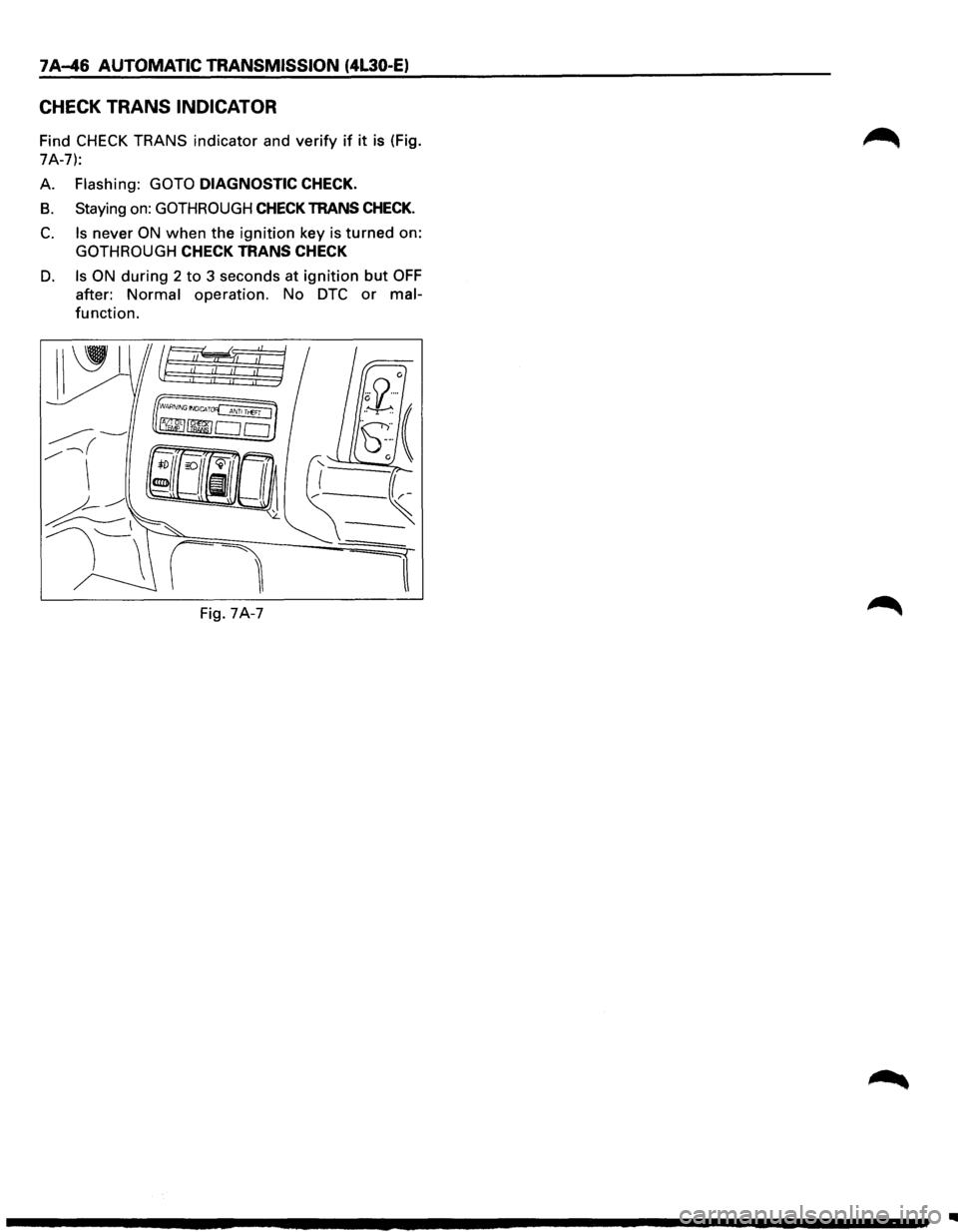
CHECK TRANS INDICATOR
Find CHECK TRANS indicator and verify if it is (Fig.
7A-7):
A.
Flashing: GOTO DIAGNOSTIC CHECK.
B. Staying on: GOTHROUGH CHECK TRANS CHECK.
C. Is never ON when the ignition key is turned on:
GOTHROUGH CHECK TRANS CHECK
D. Is ON during 2 to 3 seconds at ignition but OFF
after: Normal operation. No DTC or mal
function.
Fig. 7A-7
..
Page 919 of 1928
DIAGNOSTIC CHECK
This test determines if the transmission itself or its
~ inputs or outputs connections or sensors are failing.
IF you have a scan tool TECH1:
NO: Use the CHECK TRANS Indicator diagnostic
codes
GOTO FLASHING CODES.
YES:
1. Connect the TECH1: GOTHROUGH TECH1
CONNECTION.
2. Turn on the ignition but not the engine.
3. Push "F2" on TECH1 to see the Diagnostic
Trouble Code (OTC):
4. IF you have DTC?
YES: write down all code numbers and do the
DTCCHECK
NO: the DTC can not help you finding the
problem.
(1) GOTHROUGH "CHECK TRANS" CHECK
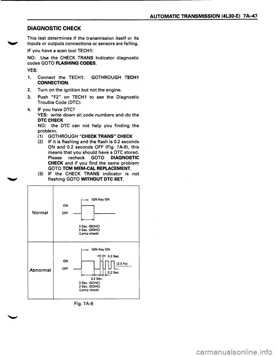
(2) IF it is flashing and the flash is 0.2 seconds
ON and 0.2 seconds OFF (Fig. 7A-8), this
means that you
should have a DTC stored.
Please recheck GOTO DIAGNOSTIC
CHECK and if you find the same problem
GOTO
TCM MEM-CAL REPLACEMENT.
(3) IF the CHECK TRANS indicator is not
........,. flashing GOTO WITHOUT DTC SET.
ON
~-IGNKeyON
__fL__ Normal OFF
w
3 Sec. (SOHC) 2 Sec. (DOHC} (Lamp check)
~-IGNKeyON
ON
~~ 0.2Sec.
~~~5-~=~--
Abnormal OFF
I. I Ill 0.2 Sec. I I I I I 3.2 Sec. 3 Sec. (SOHC) 2 Sec. (DOHC) (Lamp check}
Fig. 7A-8
AUTOMATIC TRANSMISSION (4L30-E) 7 A-47