ISUZU TROOPER 1995 Workshop Manual
Manufacturer: ISUZU, Model Year: 1995, Model line: TROOPER, Model: ISUZU TROOPER 1995Pages: 1928
Page 1091 of 1928
MANUAL TRANSMISSION 78-1
SECTION 78
MANUAL TRANSMISSION
w CAUTION
When fasteners are removed, always reinstall them at the same location from which they were removed. If a
fastener needs
to be replaced, use the correct part number fastener for that application. If the correct part
number fastener is not available, a fastener of equal size and strength (or stronger) may be used. Fasteners
that are not reused, and those requiring thread locking compound, will be called out. The correct torque
values must be used when installing fasteners that require torque. If the above conditions are not followed,
parts or system damage could result.
CONTENTS
General Description . . . . . . . . . . . . . . . . . . . . . 78-1
Construction . . . . . . . . . . . . . . . . . . . . . . . . . 78-2
Diagnosis . . . . . . . . . . . . . . . . . . . . . . . . . . . . . . 78-3
On-Vehicle Service ..................... 78-4
Transmission . . . . . . . . . . . . . . . . . . . . . . . . 78-4
Gear Control Box Assembly . . . . . . . . . . . 78-10
Unit Repair ........................... 78-12
Transmission Case And Transfer
Case .............................. 78-12
Intermediate Plate With Gear Assembly
Detent, Shift Arm, And Interlock Pin ... 78-18
Reverse Gear
And 5th Gear ............ 78-22
Top Gear Shaft, Main Gear Shaft
And Counter Gear Shaft .............. 78-29
Main Data And Specifications ............ 78-39
General Specifications ................ 78-39
Torque Specifications ................ 78-40
Special
Tools .......................... 78-43
GENERAL DESCRIPTION
The MUA5C is a constant mesh transmission,
synchronized in
all speeds. The transmission is
designed
for ease of shifting and the quietest possible
operation.
Principle parts of the transmission are the integral
clutch
housing, intermediate plate, the transfer case,
the rear cover, and the gears.
The transmission
control box and transfer control box
are
built into the transfer case.
Page 1092 of 1928
78-2 MANUAL TRANSMISSION
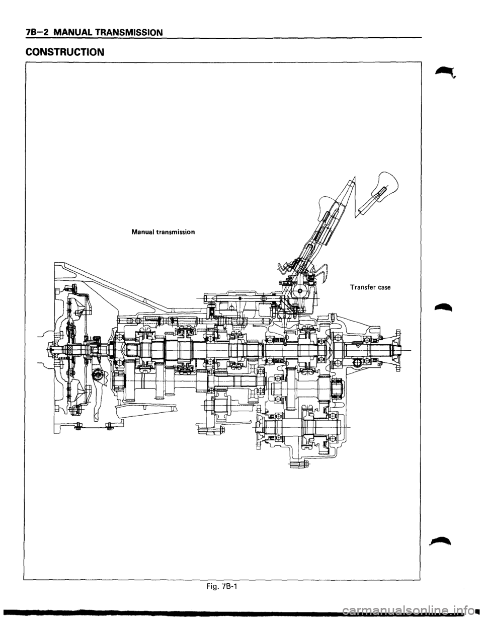
CONSTRUCTION
Manual transmission
Transfer case
Fig. 78-1
Ill
Page 1093 of 1928
MANUAL TRANSMISSION 78-3
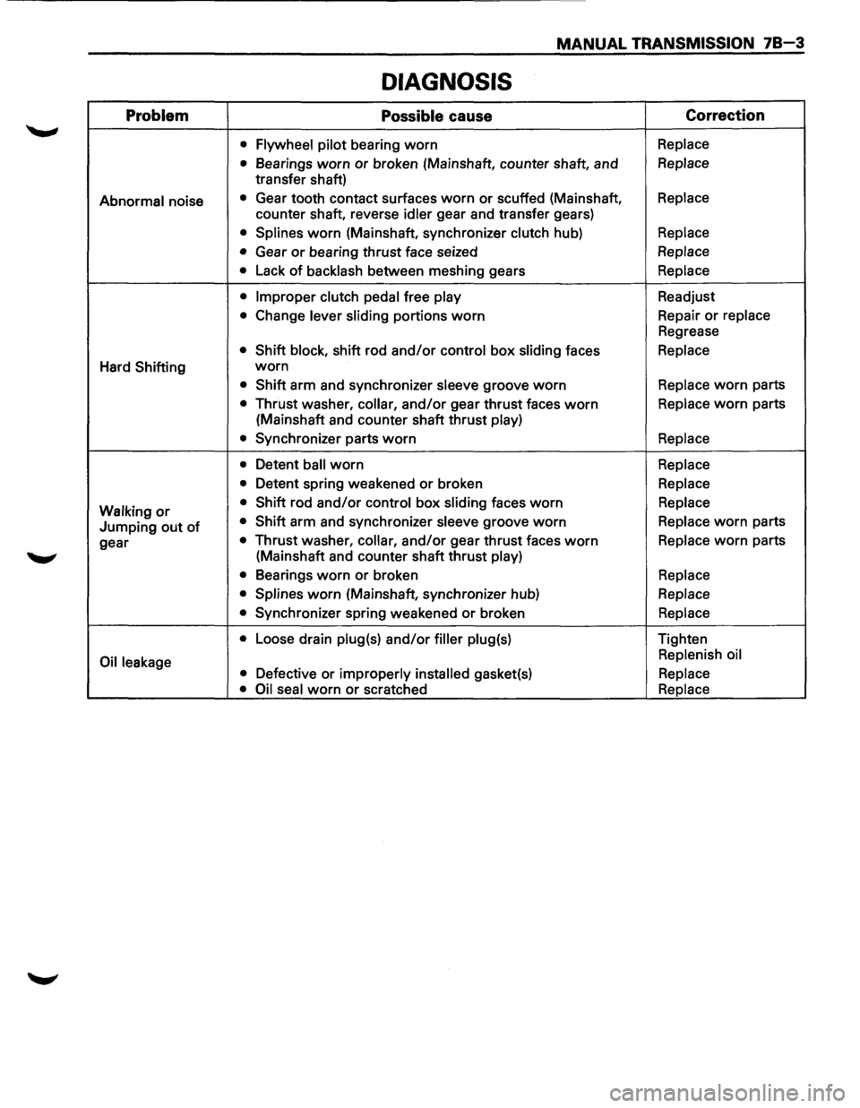
DIAGNOSIS
Problem Possible cause Correction
•
Flywheel pilot bearing worn Replace
•
Bearings worn or broken (Mainshaft, counter shaft, and Replace
transfer shaft)
Abnormal noise • Gear tooth contact surfaces worn or scuffed (Mainshaft, Replace
counter shaft, reverse idler gear and transfer gears)
• Splines worn (Mainshaft, synchronizer clutch hub) Replace
•
Gear or bearing thrust face seized Replace
•
Lack of backlash between meshing gears Replace
• Improper clutch pedal
free play Readjust
• Change lever sliding portions worn Repair or replace
Regrease
• Shift block, shift rod and/or control box sliding faces Replace
Hard Shifting worn
• Shift arm and synchronizer sleeve groove worn Replace worn parts
• Thrust washer, collar, and/or gear thrust faces worn Replace worn parts
(Mainshaft and counter shaft thrust
play)
•
Synchronizer parts worn Replace
•
Detent ball worn Replace
•
Detent spring weakened or broken Replace
Walking
or • Shift rod and/or control box sliding faces worn Replace
Jumping out of • Shift arm and synchronizer sleeve groove worn Replace worn parts
gear
• Thrust washer, collar, and/or gear thrust faces worn Replace worn parts
(Mainshaft and counter shaft thrust
play)
•
Bearings worn or broken Replace
• Splines
worn (Mainshaft, synchronizer hub) Replace
•
Synchronizer spring weakened or broken Replace
•
Loose drain plug(s) and/or filler plug(s) Tighten
Oil leakage Replenish
oil
• Defective or improperly installed gasket(s) Replace
• Oil seal
worn or scratched Replace
Page 1094 of 1928
78-4 MANUAL TRANSMISSION
ON-VEHICLE SERVICE
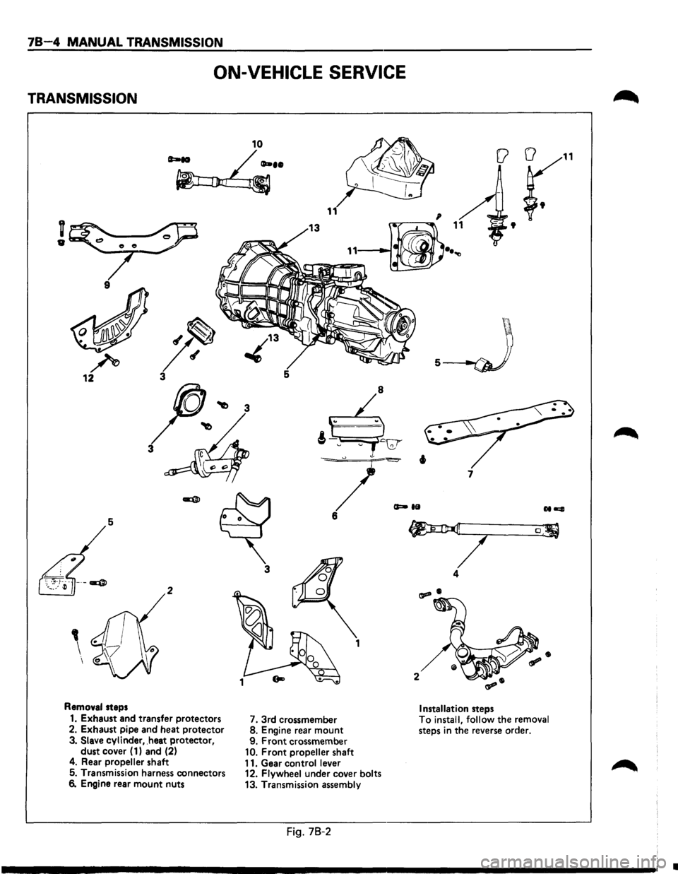
TRANSMISSION
10
~··
v
"
9
r 12 5
3
5
3
2
1
Removal steps
1. Exhaust and transfer protectors
7. 3rd crossmember
2. Exhaust pipe and heat protector 8. Engine rear mount 3. Slave cylinder, .heat protector,
9. Front crossmember dust cover ( 1) and (2) 10. Front propeller shaft
4. Rear propeller shaft
11. Gear control lever 5. Transmission harness connectors
12. Flywheel under cover bolts 6. Engine rear mount nuts
13. Transmission assembly
Fig. 78-2
(a
11
t
.__J
7
[J
4
Installation steps To install,
follow the removal steps in the reverse order.
•
Page 1095 of 1928
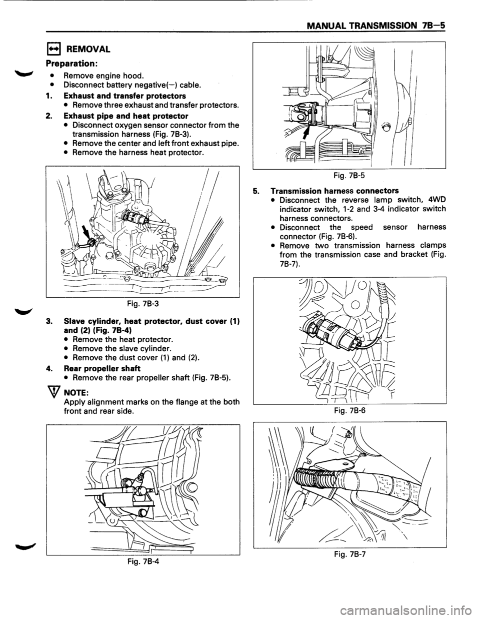
EJ REMOVAL
Preparation:
'--"' • Remove engine hood.
• Disconnect battery negative(-) cable.
1. Exhaust and transfer protectors
• Remove three exhaust and transfer protectors.
2. Exhaust pipe and heat protector
3.
• Disconnect oxygen sensor connector from the
transmission harness (Fig. 78-3).
• Remove the center and left front exhaust pipe.
• Remove the harness heat protector.
lj
Fig. 78-3
Slave cylinder, heat protector, dust cover (1)
and (2) (Fig. 78-4)
• Remove the heat protector.
• Remove the slave cylinder.
•
Remove the dust cover (1) and (2).
4. Rear propeller shaft
• Remove the rear propeller shaft (Fig. 78-5).
W NOTE:
Apply alignment marks on the flange at the both
front and rear side.
Fig. 78-4
MANUAL TRANSMISSION 78-5
Fig. 78-5
5. Transmission harness connectors
• Disconnect the reverse lamp switch, 4WD
indicator switch,
1-2 and 3-4 indicator switch
harness connectors.
• Disconnect the speed sensor harness
connector (Fig. 78-6).
• Remove two transmission harness clamps
from the transmission case and bracket (Fig.
78-7).
Fig. 78-6
Fig. 78-7
Page 1096 of 1928
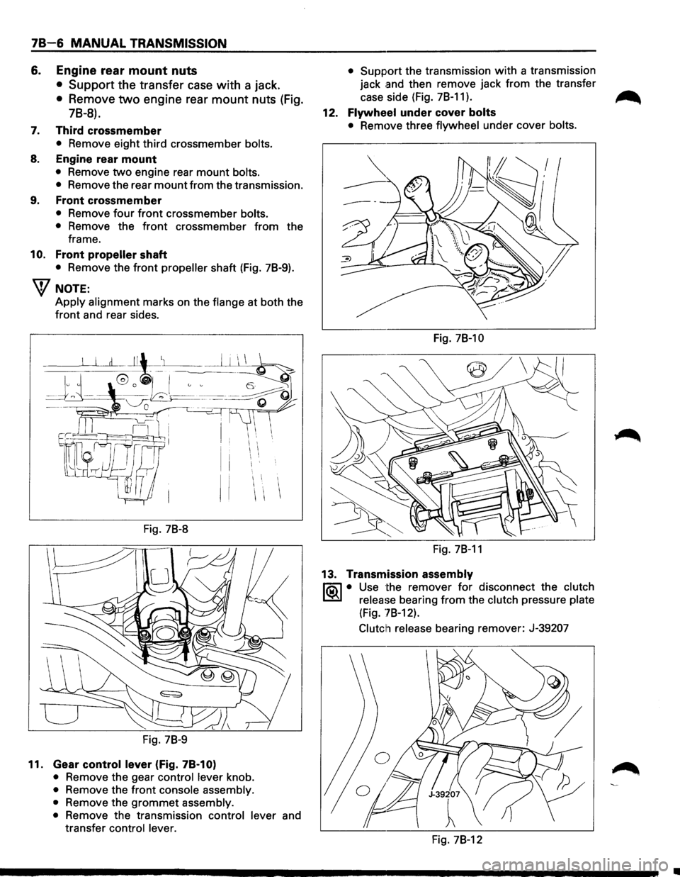
78-6 MANUAL TRANSMISSION
6. Engine rear mount nuts
• Support the transfer case with a jack.
• Remove two engine rear mount nuts (Fig.
78-8).
7. Third crossmember
• Remove eight third crossmember bolts.
8. Engine rear mount
• Remove two engine rear mount bolts.
•
Remove the rear mount from the transmission.
9. Front crossmember
• Remove four front crossmember bolts.
•
Remove the front crossmember from the
frame.
10. Front propeller shaft
• Remove the front propeller shaft (Fig. 78-9).
W NOTE:
Apply alignment marks on the flange at both the
front and rear sides.
I I I
II
Fig. 78-8
Fig. 78-9
11. Gear control lever (Fig. 78-1 0)
• Remove the gear control lever knob.
• Remove the front console assembly.
•
Remove the grommet assembly.
•
Remove the transmission control lever and
transfer
control lever. •
Support
the transmission with a transmission
jack
.and then remove jack from the transfer
case side (Fig. 78-11).
~
12. Flywheel under cover bolts
• Remove three flywheel under cover bolts.
Fig. 78-10
Fig. 78-11
13. Transmission assembly
li5\l • Use the remover for disconnect the clutch
~ release bearing from the clutch pressure plate
(Fig. '78-12).
Clutch release
bearing remover: J-39207
Fig. 78-12
•
Page 1097 of 1928
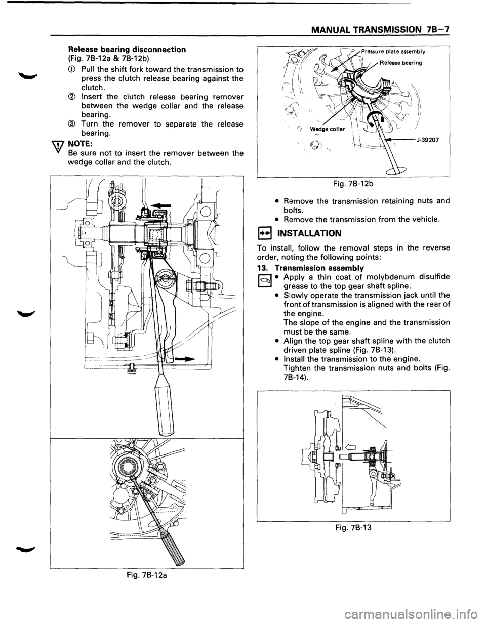
Release bearing disconnection
(Fig. 7B-12a & 7B-12b)
CD Pull the shift fork toward the transmission to
press the clutch release bearing against the
clutch.
® Insert the clutch release bearing remover
between the
wedge collar and the release
bearing.
® Turn the remover to separate the release
bearing.
IDNOTE:
Yl Be sure not to insert the remover between the
wedge collar and the clutch.
Fig. 7B-12a
MANUAL TRANSMISSION 78-7
Fig. 7B-12b
• Remove the transmission retaining nuts and
bolts.
•
Remove the transmission from the vehicle.
1••1 INSTALLATION
To install, follow the removal steps in the reverse
order, noting the
following points:
13. Transmission assembly
r;:::;J • Apply a thin coat of molybdenum disulfide
D grease to the top gear shaft spline.
• Slowly
operate the transmission jack until the
front
of transmission is aligned with the rear of
the engine.
The
slope of the engine and the transmission
must be the same.
• Align the top gear shaft spline with the clutch
driven plate spline (Fig. 78-13).
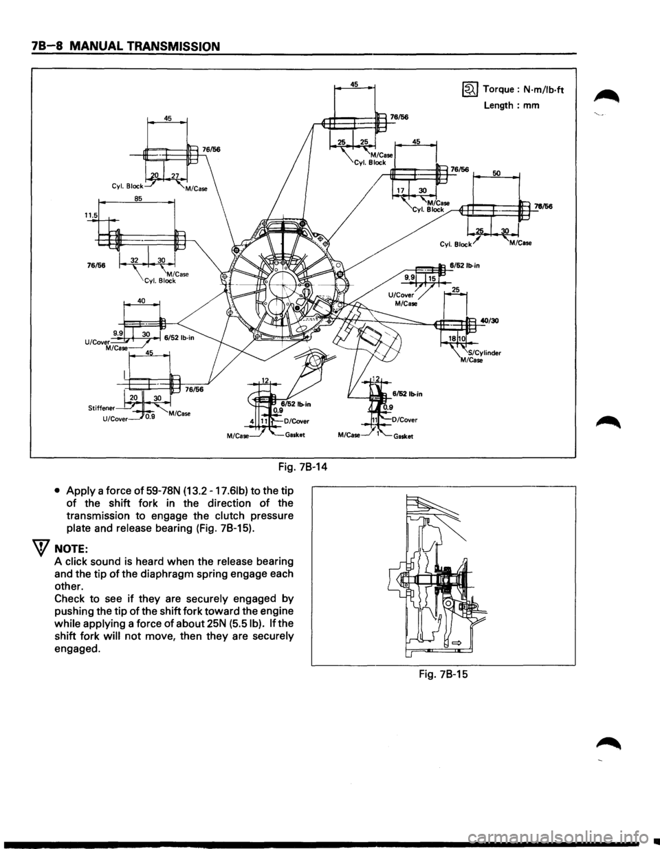
• Install the transmission to the engine.
Tighten the transmission nuts and
bolts (Fig.
78-14).
Fig. 78-13
Page 1098 of 1928
78-8 MANUAL TRANSMISSION
45
Fig. 78-14
• Apply a force of 59-78N (13.2 -17.61b) to the tip
of the shift fork in the direction of the
transmission
to engage the clutch pressure
plate and release bearing (Fig. 78-15).
W NOTE:
A click sound is heard when the release bearing
and the tip
of the diaphragm spring engage each
other.
Check
to see if they are securely engaged by
pushing the tip of the shift fork toward the engine
while applying a force
of about 25N (5.5 I b). If the
shift fork
will not move, then they are securely
engaged.
45 ~ Torque : N·m/lb·ft
Length: mm
Fig. 78-15
..
Page 1099 of 1928
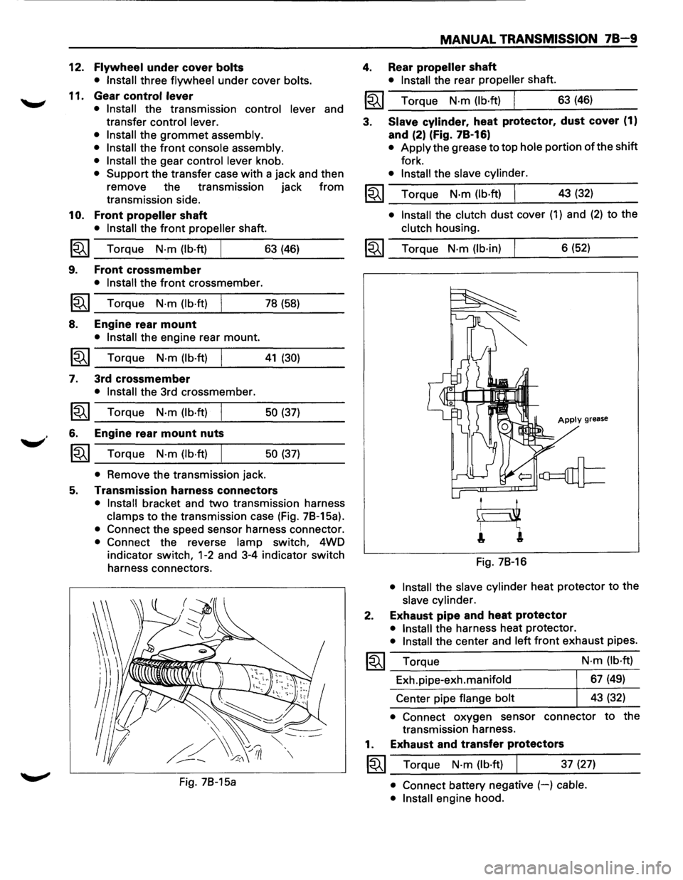
12. Flywheel under cover bolts
• Install
three flywheel under cover bolts.
11. Gear control lever
• Install
the transmission control lever and
transfer
control lever.
• Install
the grommet assembly.
• Install
the front console assembly.
• Install
the gear control lever knob.
• Support the transfer case with a jack and then
remove the transmission jack
from
transmission side.
10. Front propeller shaft
• Install the front propeller shaft.
~~~ Torque N·m (lb·ft) 63 (46)
9. Front crossmember
• Install the front crossmember.
~~~ Torque N·m (lb·ft) 78 (58)
8. Engine rear mount
• Install the engine rear mount.
~~~ Torque N·m (lb·ft) 41 (30)
7. 3rd crossmember
• Install the 3rd crossmember.
1~1 Torque N-m (lb·ft) 50 (37)
6. Engine rear mount nuts
~~~ Torque N-m (lb·ft) 50 (37)
• Remove the transmission jack.
5. Transmission harness connectors
• Install bracket and two transmission harness
clamps to the transmission case (Fig. 78-15a).
• Connect the speed sensor harness connector.
• Connect the reverse lamp switch, 4WD
indicator
switch, 1-2 and 3-4 indicator switch
harness connectors.
Fig. 78-15a
MANUAL TRANSMISSION 78-9
4. Rear propeller shaft
• Install the rear propeller shaft.
I~I __ T_o_rq~u_e __ N_·m~(_lb_·ft~)~ _____ 6_3~(_46~) ____ _
3. Slave cylinder. heat protector. dust cover (1)
and (2) (Fig. 78-16)
• Apply the grease to top hole portion of the shift
fork.
• Install the slave cylinder.
~~~ Torque N·m (lb·ft) I 43 (32) _..:....__~----
• Install the clutch dust cover (1) and (2) to the
clutch housing.
~~~ Torque N·m (lb·in) 6 (52)
Apply grease
Fig. 78-16
• Install the slave cylinder heat protector to the
slave cylinder.
2. Exhaust pipe and heat protector
• Install the harness heat protector.
• Install the center and left front exhaust pipes.
~~~ Torque
Exh.pipe-exh.manifold
Center pipe
flange bolt N·m
(lb·ft)
67 (49)
43 (32)
• Connect oxygen sensor connector to the
transmission harness.
1. Exhaust and transfer protectors
~~~ Torque N·m (lb·ft) 37 (27)
• Connect battery negative (-) cable.
• Install
engine hood.
Page 1100 of 1928
78-10 MANUAL TRANSMISSION
GEAR CONTROL BOX ASSEMBLY
l••l REMOVAL
Preparation:
• Disconnect battery negative (-) cable.
1. Knob
• Remove knobs of the transmission control
lever
and transfer control lever.
2. Front console assembly
• Remove front console assembly.
•
Disconnect harness connector.
• Remove rear heater duct.
3. Grommet assembly
• Remove grommet assembly.
4. Transmission control lever and transfer control
lever
• Remove transmission control lever and
transfer
control lever.
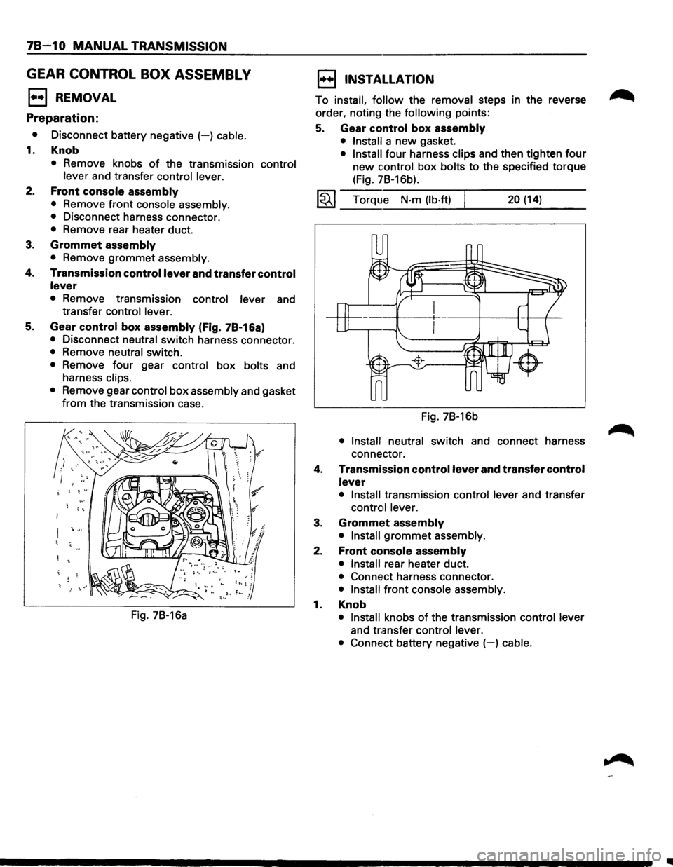
5. Gear control box assembly (Fig. 7B-16a)
• Disconnect neutral switch harness connector.
• Remove neutral switch.
• Remove four gear control box bolts and
harness
clips.
•
Remove gear control box assembly and gasket
from the transmission case.
Fig. 7B-16a
l••l INSTALLATION
To install, follow the removal steps in the reverse
order, noting the
following points:
5. Gear control box assembly
• Install a new gasket.
• Install four harness clips and then tighten four
new control box bolts to the specified torque
(Fig. 7B-16b).
1~1 Torque N·m (lb·ft) 20 (14)
Fig. 7B-16b
• Install neutral switch and connect harness
connector.
4.
Transmission control lever and transfer control
lever
• Install transmission control lever and transfer
control lever.
3. Grommet assembly
• Install grommet assembly.
2. Front console assembly
• Install rear heater duct.
• Conne,ct harness connector.
• Install front console assembly.
1. Knob
• Install knobs of the transmission control lever
and transfer control lever.
• Conne·ct
battery negative (-) cable.
•