ISUZU TROOPER 1995 Workshop Manual
Manufacturer: ISUZU, Model Year: 1995, Model line: TROOPER, Model: ISUZU TROOPER 1995Pages: 1928
Page 1061 of 1928
AUTOMATIC TRANSMISSION (4L30·E) 7A-189
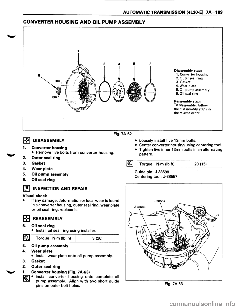
CONVERTER HOUSING AND OIL PUMP ASSEMBL V
1
Disassembly steps
1. Converter housing
2. Outer seal ring
3. Gasket
4. Wear
plate
5. Oil pump assembly
6. Oil seal ring
Reassembly steps
To reassemble, follow
the disassembly steps in the reverse order.
Fig. 7A-62
l•!•l DISASSEMBLY
1. Converter housing
• Remove five bolts from converter housing.
2. Outer seal ring
3. Gasket
4. Wear plate
5. Oil pump assembly
6. Oil seal ring
[1!) INSPECTION AND REPAIR
Visual check
• If any damage, deformation or local wear is found
in a converter housing, outer
seal ring, wear plate
or oil seal ring, replace it.
l•!•l REASSEMBLY
6. Oil seal ring
• Install oil seal ring using installer.
1~1 Torque N·m (lb·in)
5. Oil pump assembly
4. Wear plate
3 (26)
• Install wear plate onto oil pump assembly.
3. Gasket
2. Outer seal ring
"-"' 1. Converter housing (Fig. 7A-63)
li0\1 • Install converter housing onto complete oil
~ pump assembly. Align with two short guide
pins on outer
bolt holes. •
Loosely install
five 13mm bolts.
•
Center converter housing using centering tool.
•
Tighten five inner 13mm bolts in an alternating
pattern.
I~I ___ T_o_rq~u_e __ N_·_m_(_lb_·ft_)~l _____ 2_0_(_15_) ____ _
Guide pin: J-38588
Centering
tool: J-38557
J-38557
Fig. 7A-63
Page 1062 of 1928
7A-190 AUTOMATIC TRANSMISSION (4L30-E)
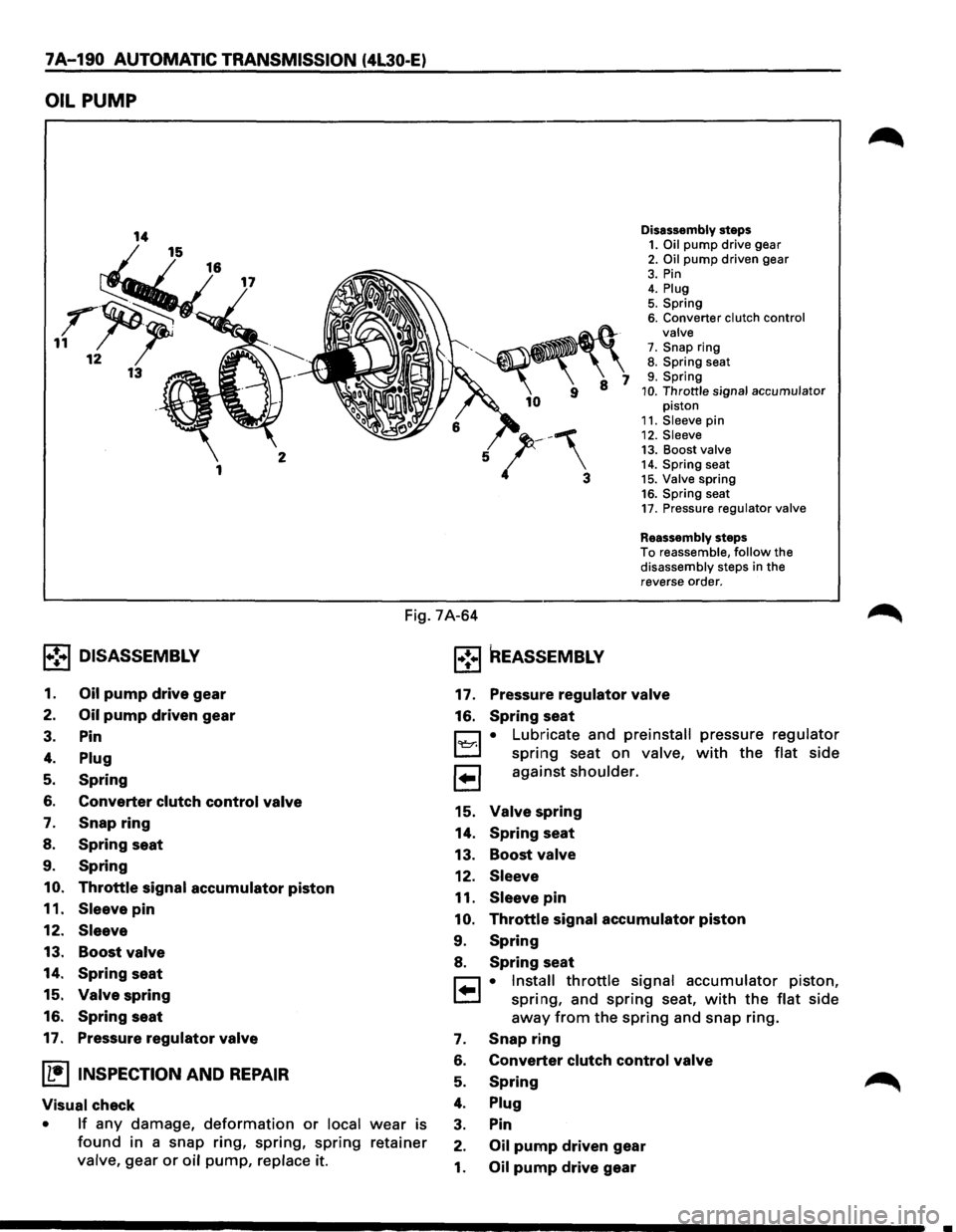
OIL PUMP
Disassembly steps 1. Oil pump drive gear 2. Oil pump driven gear 3. Pin 4. Plug 5. Spring 6. Converter clutch control
valve
7. Snap ring 8. Spring seat 9. Spring 10. Throttle signal accumulator piston 11. Sleeve pin 12. Sleeve 13. Boost valve 14. Spring seat 15. Valve spring 16. Spring seat 17. Pressure regulator valve
Reassembly steps
To reassemble, follow the disassembly steps in the
reverse order.
Fig. 7A-64
1+!•1 DISASSEMBLY
1. Oil pump drive gear
2. Oil pump driven gear
3. Pin
4. Plug
5. Spring
6. Converter clutch control valve
7. Snap ring
8. Spring seat
9. Spring
10. Throttle signal accumulator piston
11. Sleeve pin
12. Sleeve
13. Boost valve
14. Spring seat
15.
Valve spring
16. Spring seat
17. Pressure regulator valve
ll..•ltNSPECTION AND REPAIR
Visual check
• If any damage, deformation or local wear is
found in a snap ring, spring, spring retainer
valve,
gear or oil pump, replace it.
l•!•l REASSEMBLY
17. Pressure regulator valve
16. Spring seat
0 • Lubricate and preinstall pressure
L::::J spring seat on valve, with the
1 .. 1 against shoulder.
15. Valve spring
14. Spring seat
13.
Boost valve
12. Sleeve
11. Sleeve pin
10. Throttle signal accumulator piston
9. Spring
8. Spring seat
regulator
flat side
r=1 • Install throttle signal accumulator piston,
t.=..l spring, and spring seat, with the flat side
away from the spring and snap ring.
7. Snap ring
6. Converter clutch control valve
5. Spring
4. Plug
3. Pin
2. Oil pump driven gear
1. Oil pump drive gear
Page 1063 of 1928
~
AUTOMATIC TRANSMISSION (4L30-E) 7A-191
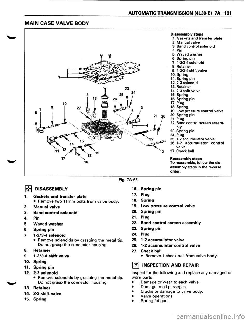
MAIN CASE VALVE BODY
1·:-1
1.
2.
3.
4.
5.
6.
7.
8.
9.
10.
11.
12.
13.
14.
15.
23
8 25 i 24
26
r t 1
~kY~ 3
"· u 21 20
/:: 14 4 11
~ 2
16
Fig. 7A-65
DISASSEMBLY 16. Spring pin
Gaskets
and transfer plate 17. Plug
Disassembly steps
1. Gaskets and transfer plate 2. Manual valve
3. Band control solenoid 4. Pin 5. Waved washer
6. Spring pin 7. 1-2/3-4 solenoid
8. Retainer 9. 1-2/3-4 shift valve 10. Spring
11. Spring pin 12. 2-3 solenoid
13. Retainer 14. 2-3 shift valve 15. Spring
16. Spring pin 17. Plug 18. Spring
19. Low pressure control valve
20. Spring pin 21. Plug
22. Band control screen assem-bly
23. Spring pin 24. Plug
25. 1-2 accumulator valve 26. 1-2 accumulator control valve
27. Check ball
Reassembly
steps
To reassemble,
follow the dis
assembly steps in the reverse
order.
• Remove two 11 mm bolts from valve body. 18. Spring
Manual valve 19. Low pressure control valve
Band control solenoid 20. Spring pin
Pin 21.
Plug
Waved washer 22.
Band control screen assembly
Spring pin 23. Spring pin
1-2/3-4 solenoid 24. Plug
•
Remove solenoids by grasping the metal tip. 25.
1-2 accumulator valve
Do not grasp the connector housing.
26. 1-2 accumulator control valve
Retainer 27. Check ball
1-2/3-4 shift valve • Remove 1 check ball from valve body.
Spring IL•I INSPECTION AND REPAIR Spring pin
2-3 solenoid Inspect for the following and replace any damaged or
• Remove solenoids by grasping the metal tip. worn parts:
Do
not grasp the connector housing. • Damage or wear to each valve.
Retainer • Damage in oil passages .
2-3
shift valve • Cracks or damage to valve body .
• Valve operations . Spring • Spring fatigue .
Page 1064 of 1928
7A 192 AUTOMATIC TRANSMISSION (4L30-E)
l•!•l REASSEMBL V
27. Check ball
• Install
1 check ball to valve body
26. 1-2
accumulator control valve
25. 1-2 accumulator valve
24. Plug
23. Spring pin
22. Band
control screen assembly
21. Plug
20.
Spring pin
19.
Low pressure control valve
18. Spring
17. Plug
16. Spring pin
15.
Spring
14. 2-3 shift valve
13.
Retainer
12. 2-3
solenoid
11. Spring pin
10. Spring
9. 1-2/3-4 shift valve
8. Retainer
7. 1-2/3-4 solenoid
6. Spring pin
5. Waved washer
4. Pin
3. Band control solenoid
2. Manual valve
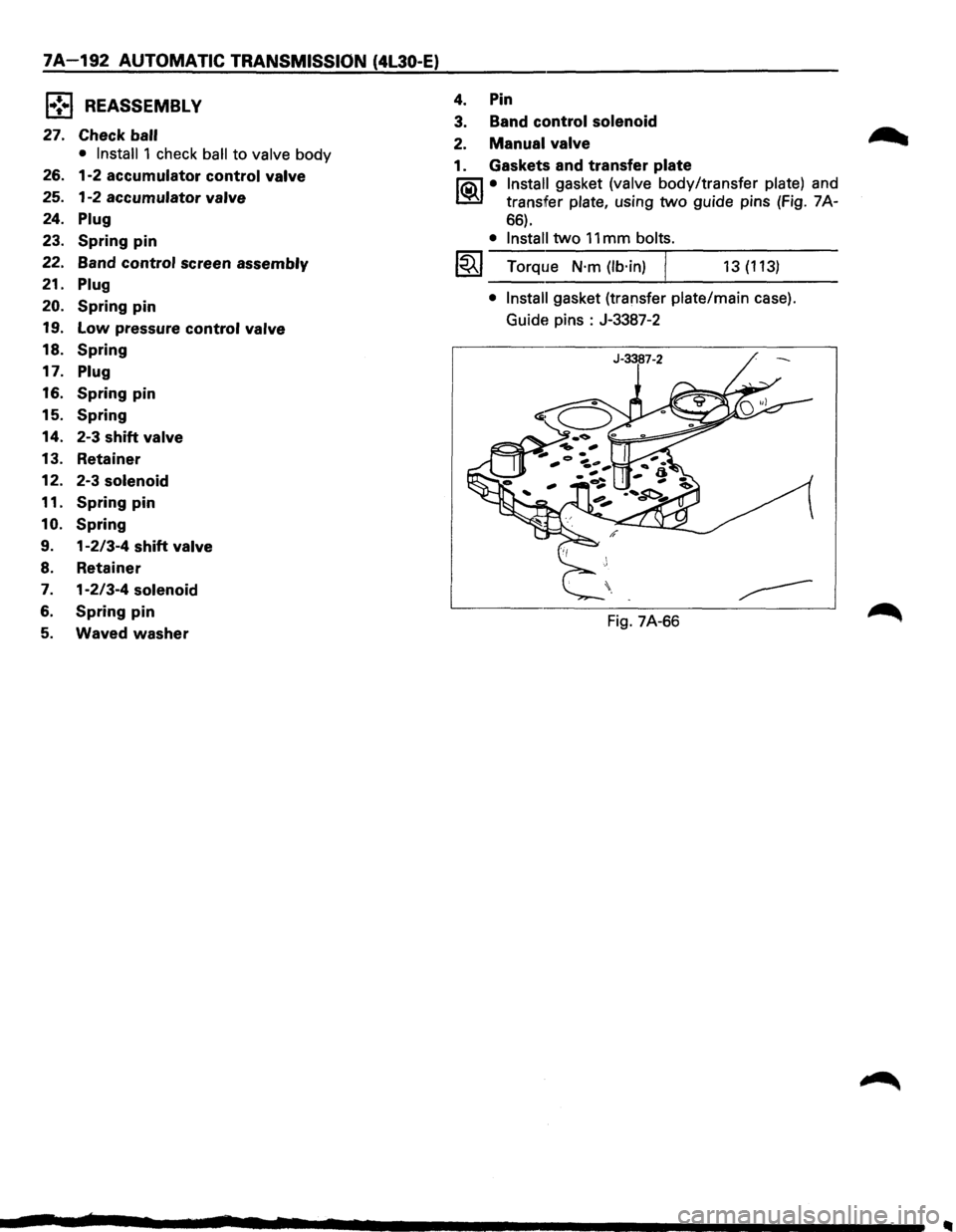
1. Gaskets and transfer plate
li5\l • Install gasket (valve body/transfer plate) and
~ transfer plate, using two guide pins (Fig. 7A-
66).
• Install two 11 mm bolts.
1~1 Torque N·m (lb·in) j 13 (113)
• Install gasket (transfer plate/main case).
Guide pins :
J-3387-2
Fig. 7A-66
Page 1065 of 1928
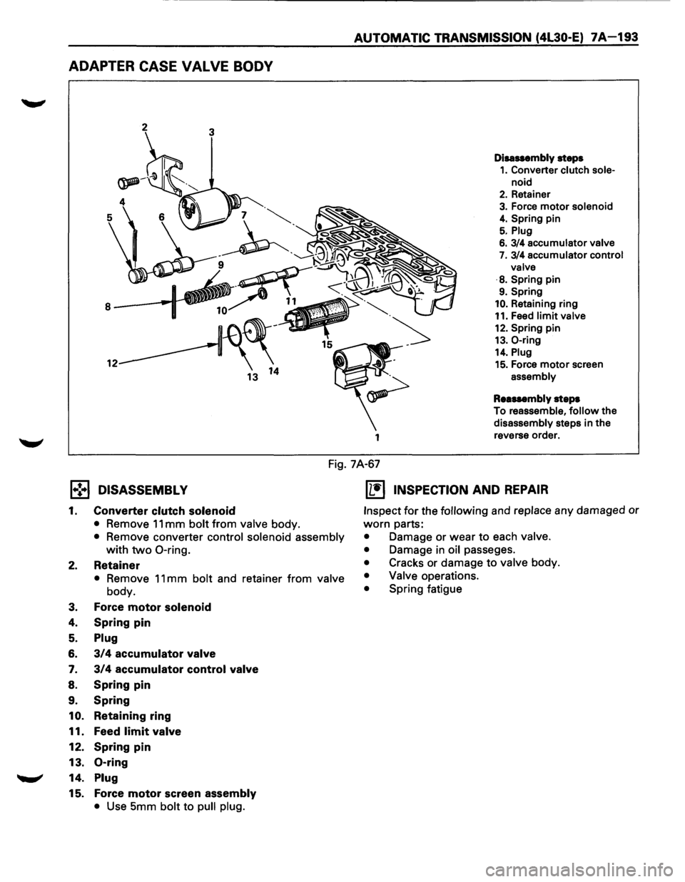
ADAPTER CASE VALVE BODY
AUTOMATIC TRANSMISSION (4L30-E) 7A-193
1
Disassembly steps
1. Converter clutch sole-
noid
2. Retainer
3. Force motor solenoid
4. Spring pin
5. Plug
6. 3/4 accumulator valve
7. 3/4 accumulator control
valve
·
8. Spring pin
9. Spring
10. Retaining ring
11. Feed limit valve
12. Spring pin
13. 0-ring
14. Plug
15. Force motor screen
assembly
Reassembly
steps
To
reassemble, follow the
disassembly steps in the
reverse order.
Fig. 7A-67
l.,!,.l DISASSEMBL V
1. Converter clutch solenoid
• Remove 11 mm bolt from valve body.
• Remove converter control solenoid assembly
with two 0-ring.
2. Retainer
• Remove 11 mm bolt and retainer from valve
body.
3. Force motor solenoid
4. Spring pin
5. Plug
6. 3/4 accumulator valve
7. 3/4 accumulator control valve
8. Spring pin
9.
Spring
10. Retaining ring
11. Feed
limit valve
12. Spring pin
13. 0-ring
14. Plug
15. Force motor screen assembly
• Use 5mm bolt to pull plug.
(L!] INSPECTION AND REPAIR
Inspect for the following and replace any damaged or
worn parts:
• Damage or wear to each valve.
•
Damage in oil passages.
• Cracks or damage to valve body.
• Valve operations.
• Spring fatigue
Page 1066 of 1928
7A-194 AUTOMATIC TRANSMISSION (4L30-E)
f•!•l REASSEMBLY
15. Force motor screen assembly
14. Plug
13. 0-ring
12. Spring pin
11. Feed
limit valve
10. Retaining ring
9. Spring
8. Spring pin
7. 3/4 accumulator control valve
6. 3/4 accumulator valve
5. Plug
4. Spring pin
3. Force motor solenoid
2. Retainer
r=1 • Plac_e solenoid terminals pointing towards
1=.1 matmg face.
• Install retainer and bolt.
~~~ Torque N·m (lb·in) I 10 (87)
1. Converter clutch solenoid
• Install converter clutch solenoid assembly with
two 0-rings to valve body.
• Install bolt.
~~~ Torque N·m (lb·in) I 10 (87)
Page 1067 of 1928
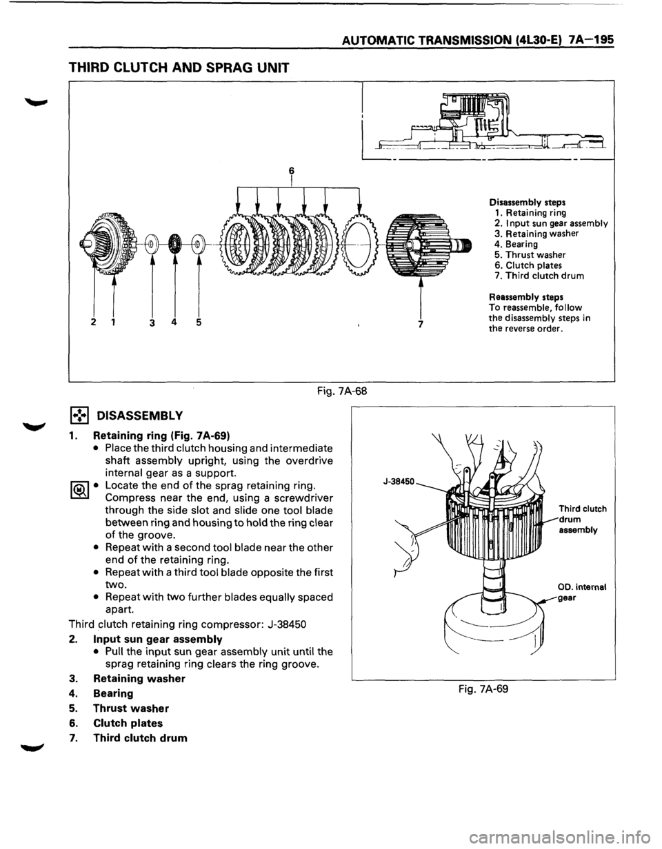
THIRD CLUTCH AND SPRAG UNIT
AUTOMATIC TRANSMISSION (4L30-E) 7A-195
Disassembly steps
1. Retaining ring
2. Input sun gear assembly 3. Retaining washer 4. Bearing 5. Thrust washer 6. Clutch plates 7. Third clutch drum
Reassembly steps
To reassemble, follow the disassembly steps in the reverse order.
Fig. 7A-68
1•! .. 1 DISASSEMBL V
1. Retaining ring (Fig. 7A-69)
• Place the third clutch housing and intermediate
shaft
assembly upright, using the overdrive
internal gear as a support.
I®J • Locate the end of the sprag retaining ring.
Compress near the
end, using a screwdriver
through the side
slot and slide one tool blade
between ring and housing to hold the ring clear
of the groove.
• Repeat with a second tool blade near the other
end
of the retaining ring.
• Repeat with a third tool blade opposite the first
two.
• Repeat with two further blades equally spaced
apart.
Third
clutch retaining ring compressor: J-38450
2. Input sun gear assembly
3.
4.
5.
6.
7.
• Pull the input sun gear assembly unit until the
sprag retaining ring
clears the ring groove.
Retaining washer
Bearing
Thrust washer
Clutch plates
Third clutch drum
Fig. 7A-69
Third clutch
drum
assembly
00. internal
Page 1068 of 1928
7A-196 AUTOMATIC TRANSMISSION (4L30-E)
IL•IINSPECTION AND REPAIR
Visual check
• If any damage, deformation or local wear is
found in a bearing, thrust washer, clutch plates
or third clutch drum, replace it.
l•!•l REASSEMBLY
7. Third clutch drum
6. Clutch plates
• Place third clutch housing and intermediate
shaft assembly upright, using the overdrive
internal gear
as a support.
, .. , • Install third clutch spring cushion plate,
bevel face
down.
• Install third clutch plates into clutch housing.
Start
with the steel clutch plate and alternate
with lined plates.
5.
Thrust washer
4. Bearing
3. Retaining washer
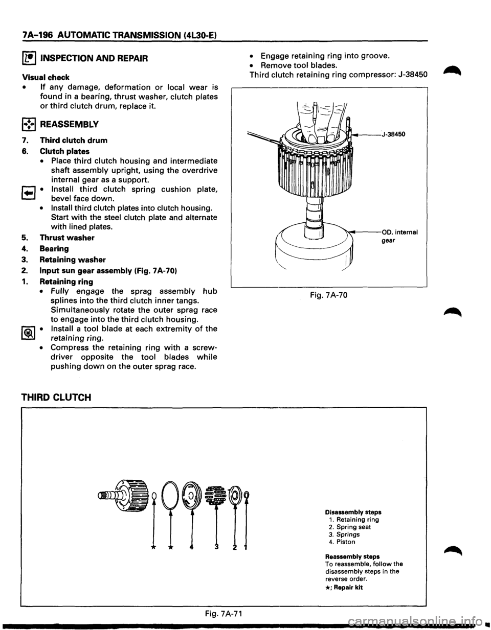
2. Input sun gear assembly (fig. 7A-70)
1. Retaining ring
• Fully engage the sprag assembly hub
splines into the third clutch inner tangs.
Simultaneously rotate the outer sprag race
to engage into the third clutch housing.
1®.1 • Install a tool blade at each extremity of the
retaining ring.
• Compress the retaining ring with a screw
driver opposite the tool blades while
pushing down on the outer sprag race.
THIRD CLUTCH
Fig. 7A-71
• Engage retaining ring into groove.
• Remove tool blades.
Third clutch retaining ring compressor: J-38450
J.4---J-38450
~~--oo. internal
gear
Fig. 7A-70
Disassembly steps 1. Retaining ring 2. Spring seat 3. Springs 4. Piston
Reassembly steps
To reassemble, follow the
disassembly steps in the
reverse order.
*; Repair kit
Page 1069 of 1928
l•!•l DISASSEMBLY
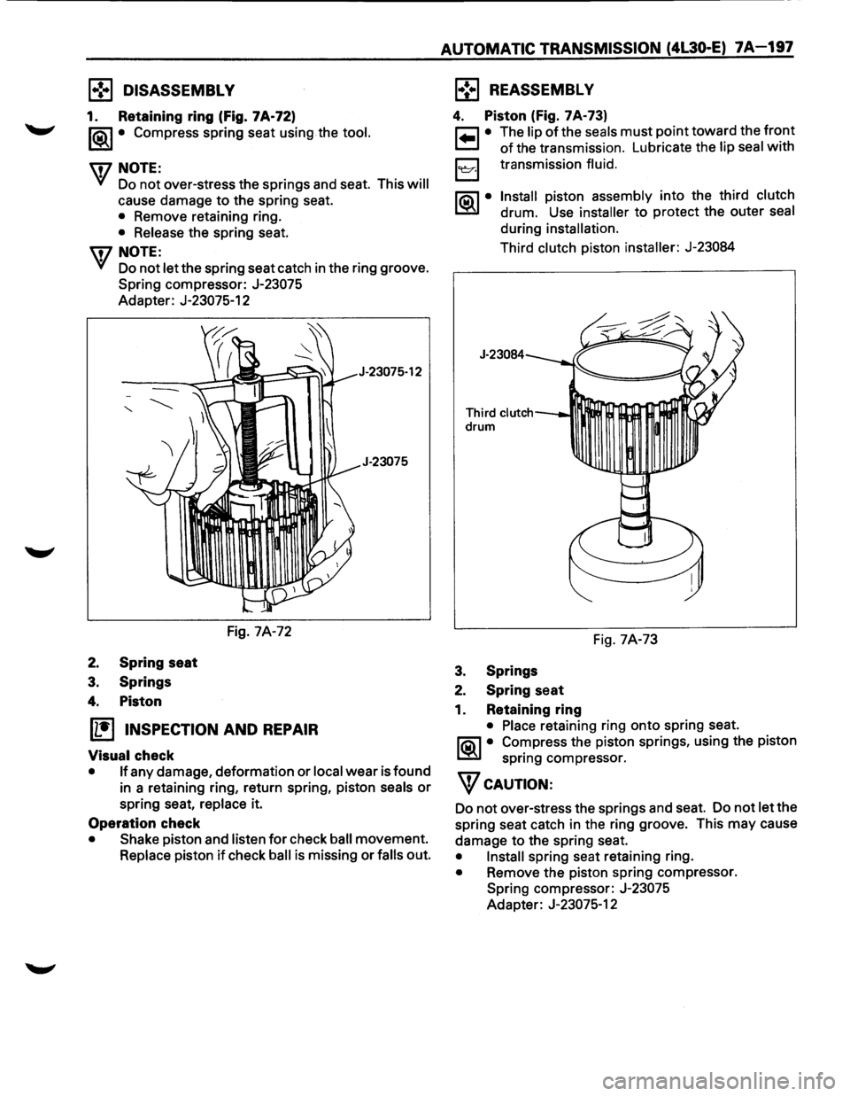
1. Retaining ring (Fig. 7A·72)
1®.1• Compress spring seat using the tool.
U7 NOTE:
VI Do not over-stress the springs and seat. This will
cause damage to the spring seat.
• Remove retaining ring.
• Release the spring seat.
U7 NOTE:
VI Do not let the spring seat catch in the ring groove.
Spring compressor: J-23075
Adapter: J-23075-12
Fig. 7A-72
2. Spring seat
3. Springs
4. Piston
~ INSPECTION AND REPAIR
Visual check
J-23075-12
J-23075
• If any damage, deformation or local wear is found
in a retaining ring, return spring, piston
seals or
spring seat, replace it.
Operation check
• Shake piston and listen for check ball movement.
Replace piston if check ball is missing or falls out.
AUTOMATIC TRANSMISSION (4L30-E) 7A-197
l•!•l REASSEMBLY
4. Piston (Fig. 7A·73)
r=1 • The lip of the seals must point toward the front
t=J of the transmission. Lubricate the lip seal with
loe:r·l transmission fluid.
~·
Install piston assembly into the third clutch
drum. Use installer to protect the outer seal
during installation.
Third clutch piston installer: J-23084
J-23084
Third clutch----•n drum
Fig. 7A-73
3. Springs
2. Spring seat
1. Retaining ring
• Place retaining ring onto spring seat.
~ • Co~press the piston springs, using the piston
sprmg compressor.
WcAUTION:
Do not over-stress the springs and seat. Do not let the
spring seat catch in the ring groove. This may cause
damage to the spring seat.
• Install spring seat retaining ring.
• Remove the piston spring compressor.
Spring compressor: J-23075
Adapter: J-23075-12
Page 1070 of 1928
7A-198 AUTOMATIC TRANSMISSION (4L30-E)
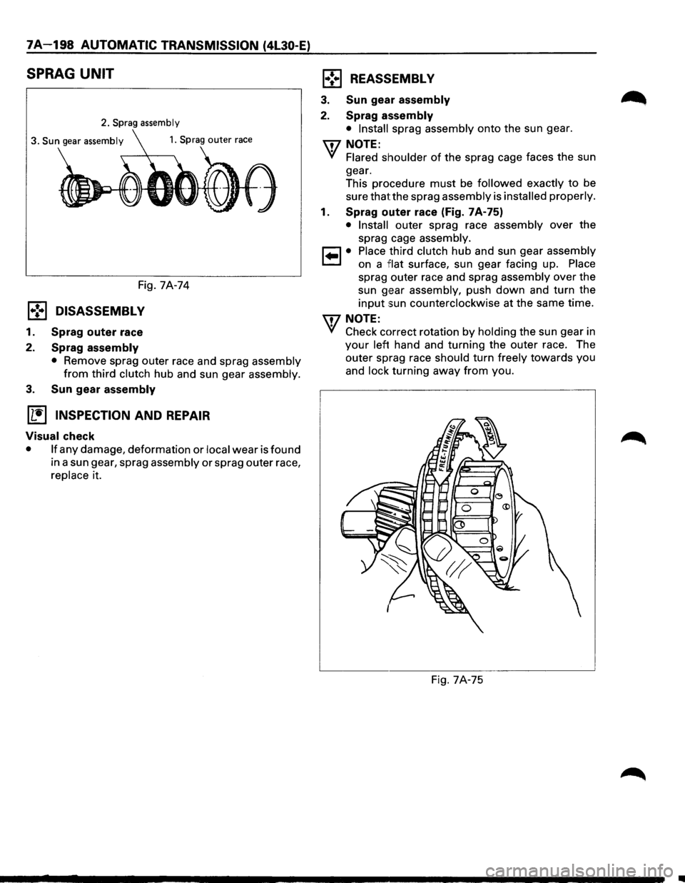
SPRAG UNIT
2. Sprag assembly
3. Sun gear assembly
Fig. 7A-74
1.,!•1 DISASSEMBLY
1. Sprag outer race
2.
Sprag assembly
• Remove sprag outer race and sprag assembly
from third clutch hub and sun gear assembly.
3. Sun gear assembly
(1!] INSPECTION AND REPAIR
Visual check
• If any damage, deformation or local wear is found
in a sun gear, sprag assembly or sprag outer race,
replace it.
1•! .. 1 REASSEMBLY
3. Sun gear assembly
2. Sprag assembly
• Install sprag assembly onto the sun gear.
\fl NOTE:
VI Flared shoulder of the sprag cage faces the sun
gear.
This procedure
must be followed exactly to be
sure that the sprag assembly is
installed properly.
1. Sprag outer race (Fig. 7A-75)
• Install outer sprag race assembly over the
sprag cage assembly.
1•1• Place third clutch hub and sun gear assembly
on a
1Fiat surface, sun gear facing up. Place
sprag outer race and sprag assembly over the
sun
g,ear assembly, push down and turn the
input sun counterclockwise at the same time.
\fl NOTE:
VI Check correct rotation by holding the sun gear in
your left hand and turning the outer race. The
outer sprag race should turn freely
towards you
and
lock turning away from you.
Fig. 7A-75
•