ISUZU TROOPER 1995 Workshop Manual
Manufacturer: ISUZU, Model Year: 1995, Model line: TROOPER, Model: ISUZU TROOPER 1995Pages: 1928
Page 1071 of 1928
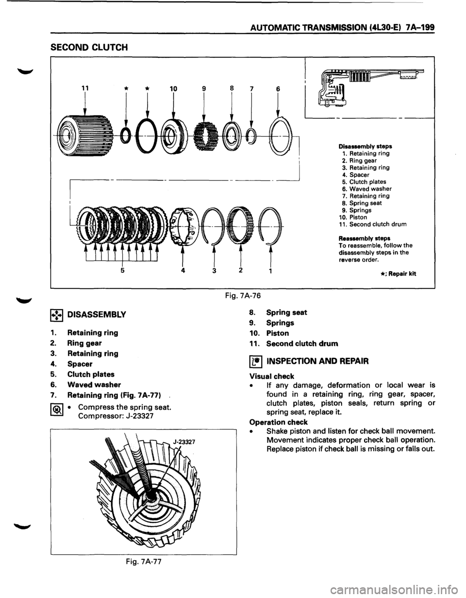
SECOND CLUTCH
5 4
1•!•1 DISASSEMBLY
1. Retaining ring
2. Ring gear
3. Retaining ring
4. Spacer
5.
Clutch plates
6. Waved washer
7. Retaining ring (fig. 7A-77)
~~~ • Compress the spring seat.
Compressor: J-23327
Fig. 7A-77
AUTOMATIC TRANSMISSION (4L30-E) 7 A-199
'
__ _j
1
Fig. 7A-76
8.
Spring seat
9.
Springs
10. Piston
11. Second
clutch drum
Disassembly steps 1. Retaining ring 2. Ring gear 3. Retaining ring 4. Spacer 5. Clutch plates 6. Waved washer 7. Retaining ring 8. Spring seat 9. Springs 10. Piston 11. Second clutch drum
Reassembly steps
To reassemble, follow the
disassembly steps in the
reverse order.
*; Repair kit
I L•IINSPECTION AND REPAIR
Visual check
• If any damage, deformation or local wear is
found in a retaining ring, ring gear, spacer,
clutch plates, piston seals, return spring or
spring seat, replace it.
Operation check
• Shake piston and listen for check ball movement.
Movement indicates proper check
ball operation.
Replace piston if check ball is missing or falls out.
Page 1072 of 1928
7 A-200 AUTOMATIC TRANSMISSION (4L30-E)
l•!•l REASSEMBLY
11. Second clutch drum
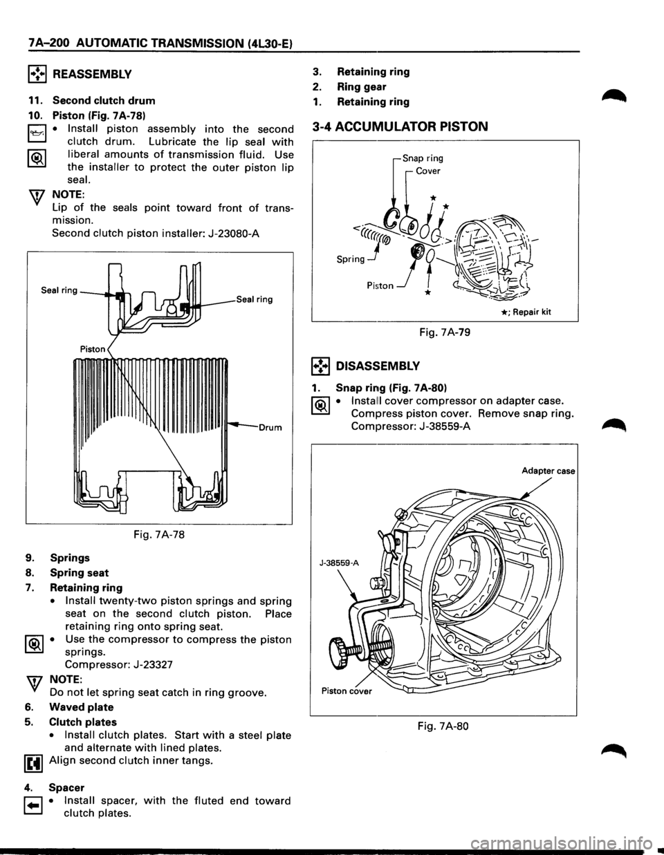
10. Piston (Fig. 7A-78)
0 • Install piston assembly into the second
t..::::::.:J clutch drum. Lubricate the lip seal with
1®..1 liberal amounts of transmission fluid. Use
the installer to protect the outer piston lip
seal.
W NOTE:
Lip of the seals point toward front of trans
mission.
Second clutch piston installer: J-23080-A
Seal ring
3. Retaining ring
2. Ring gear
1. Retaining ring
3-4 ACCUMULATOR PISTON
,Snap ring
Cover
* *
<·-' ~·· ··~
Spring Jr-J
1
t -;;~~H -~, ~:·.-... , ' ~ '-'FJ:
Pi!;ton * ~~+_z.~~
*;Repair kit
Fig. 7A-79
1•!•1 DISASSEMBLY
1. Snap ring (Fig. 7 A-80)
l?.i\1 • Install! cover compressor on adapter case.
~ Compress piston cover. Remove snap ring.
Drum Compressor: J-38559-A
Fig. 7A-78
9. Springs
8. Spring seat
7. Retaining ring
• Install twenty-two piston springs and spring
seat on the second clutch piston. Place
retaining ring onto spring seat.
1 ®..I • Use the compressor to compress the piston
springs.
Compressor: J-23327
w NOTE:
Do not let spring seat catch in ring groove.
6. Waved plate
5. Clutch plates
• Install clutch plates. Start with a steel plate
and alternate with lined plates.
IEtl Align second clutch inner tangs.
4. Spacer
r::1 • Install spacer, with the fluted end toward
t.:=.l clutch plates.
Adapter case
Fig. 7A-80
•
Page 1073 of 1928
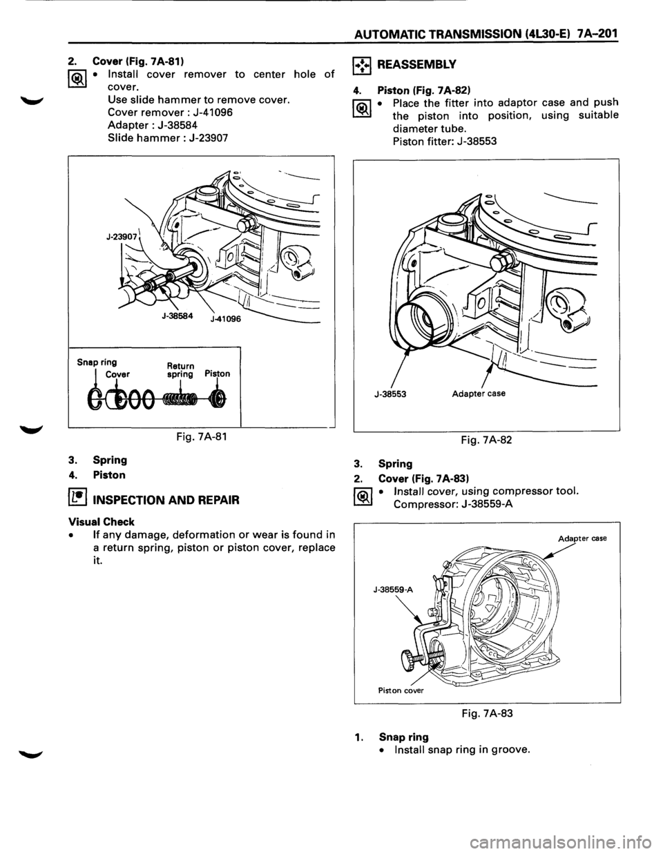
2. Cover (Fig. 7A-81)
1®.1 • Install cover remover to center hole of
cover.
Use slide
hammer to remove cover.
Cover
remover: J-41096
Adapter: J-38584
Slide
hammer : J-23907
Snap ring
Fig. 7A-81
3. Spring
4. Piston
I L•IINSPECTION AND REPAIR
Visual Check
• If any damage, deformation or wear is found in
a return
spring, piston or piston cover, replace
it.
AUTOMATIC TRANSMISSION (4L30-E) 7 A-201
l•!•l REASSEMBLY
4. Piston (Fig. 7 A-82)
l"'iQ\1 • Place the fitter into a~~ptor ca~e and. push
~ the piston into pos1t1on, usmg su1table
diameter tube.
Piston fitter: J-38553
J-38553 Adapter case
Fig. 7A-82
3. Spring
2. Cover (Fig. 7 A-83)
l"'iQ\1 • Install cover, using compressor tool.
~ Compressor: J-38559-A
Adapter case
Piston cover
Fig. 7A-83
1. Snap ring
• Install snap ring in groove.
Page 1074 of 1928
7A-202 AUTOMATIC TRANSMISSION (4l30-E)
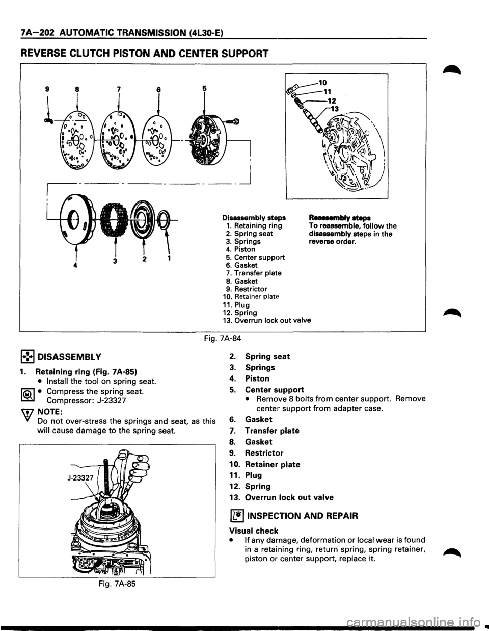
REVERSE CLUTCH PISTON AND CENTER SUPPORT
9
i
____ j
Disassembly steps 1. Retaining ring 2. Spring seat
3. Springs 4. Piston
5. Center support 6. Gasket 7. Transfer plate
8. Gasket 9. Restrictor 10. Retainer plate
11. Plug 12. Spring
RusMmbly steps To reassemble, follow the
disassembly steps in the
reverse order.
13. Overrun lock out valve
Fig. 7A-84
1•! .. 1 DISASSEMBLY
1. Retaining ring (fig. 7A-85)
• Install the tool on spring seat.
liC\1 • Compress the spring seat.
~ Compressor: J-23327
W NOTE:
¥1 Do not over-stress the springs and seat, as this
will cause damage to the spring seat.
Fig.
7A-85
2. Spring seat
3. Springs
4. Piston
5. Center support
• Remove 8 bolts from center support.
center· support from adapter case.
6. Gasket
7. Transfer plate
8. Gasket
9. Restrict<,r
10. Retainer plate
11. Plug
12. Spring
13. Overrun lock out valve
IL•IINSPECTION AND REPAIR
Visual check Remove
•
If any damage, deformation or local wear is found
in a retaining ring, return spring, spring retainer,
~
piston or center support, replace it.
..
Page 1075 of 1928
1 .. !•1 REASSEMBL V
13. Overrun lock out valve
........,
12. Spring
• Install overrun lock out valve and spring.
\fJ NOTE:
VI Ensure correct assembly of valve. The spring
should be located over the long small diameter
end.
11. Plug
10.
Pin
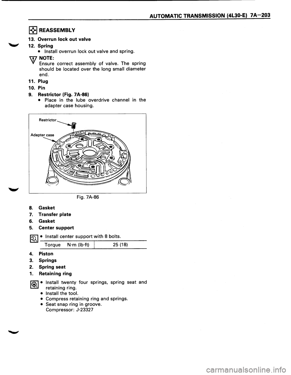
9. Restrictor (Fig. 7A·86)
• Place in the lube overdrive channel in the
adapter case housing.
8. Gasket
7. Transfer plate
6. Gasket
5. Center support
Fig. 7A-86
~~~· Install center support with 8 bolts.
Torque N·m (lb·ft) I 25 (18)
4. Piston
3. Springs
2. Spring seat
1. Retaining ring
1®.1• Install twenty four springs, spring seat and
retaining ring.
• Install the tool.
•
Compress retaining ring and springs.
• Seat snap ring in groove.
Compressor: J-23327
AUTOMATIC TRANS.MISSION (4L30-E) 7A-203
Page 1076 of 1928
7 A-204 AUTOMATIC TRANSMISSION (4l30-E)
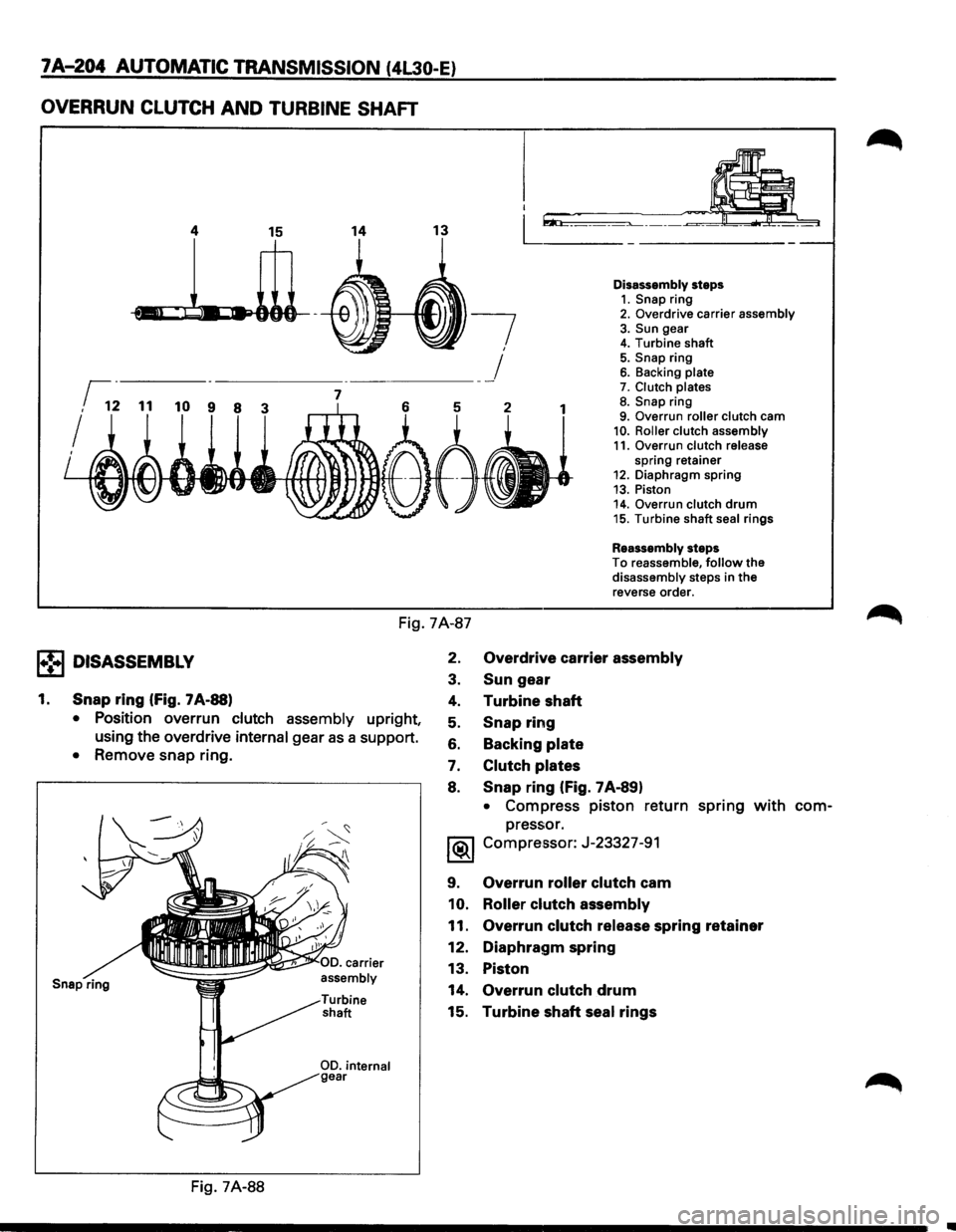
OVERRUN CLUTCH AND TURBINE SHAFT
I
I '
.L.llL
14
-·
13 L~L
Disassembly steps 1. Snap ring 2. Overdrive carrier assembly 3. Sun gear 4. Turbine shaft
---------___________________________ _! 5. Snap ring 6. Backing plate 7. Clutch plates 7 8. Snap ring 9. Overrun roller clutch cam 10. Roller clutch assembly 11. Overrun clutch release spring retainer 12. Diaphragm spring 13. Piston 14. Overrun clutch drum 15. Turbine shaft seal rings
Reassembly steps
To reassemble, follow the disassembly steps in the
reverse order.
Fig. 7A-87
EE DISASSEMBLY
1. Snap ring (fig. 7 A-88)
• Position overrun clutch assembly upright,
using the overdrive
internal gear as a support.
• Remove snap ring.
Fig. 7A-88 2.
Overdrive carrier
assembly
3. Sun gear
4. Turbine shaft
5. Snap ring
6. Backing plate
7. Clutch plates
8. Snap ring (fig. 7 A-891
• Compress piston return spring with com-
pressor.
1®..1 Compressor: J-23327-91
9. Overrun roller clutch cam
10. Roller clutch assembly
11. Overrun clutch release spring retainer
12. Diaphragm spring
13. Piston
14. Overrun clutch drum
15. Turbine shaft seal rings
•
Page 1077 of 1928
![ISUZU TROOPER 1995 Workshop Manual J-23327-91
Roller clutch assembiy
Fig. 7A-89
li:!] INSPECTION AND REPAIR
Overdrive carrier check (Fig. 7A-90)
Snap ring
1@1• Check pinion end play with a feeler gage.
Clearance mm (in) I 0](/img/61/57183/w960_57183-1076.png "ISUZU TROOPER 1995 Workshop Manual J-23327-91
Roller clutch assembiy
Fig. 7A-89
li:!] INSPECTION AND REPAIR
Overdrive carrier check (Fig. 7A-90)
Snap ring
1@1• Check pinion end play with a feeler gage.
Clearance mm (in) I 0")
J-23327-91
Roller clutch assembiy
Fig. 7A-89
li:!] INSPECTION AND REPAIR
Overdrive carrier check (Fig. 7A-90)
Snap ring
1@1• Check pinion end play with a feeler gage.
Clearance mm (in) I 0.24-0.64 (0.0094-0.025)
If clearance
is outside specified value, replace
overdrive carrier assembly.
Overdrive carrier
on
Fig. 7A-90
Visual
check
• If any damage, deformation or local wear is found
in a snap ring, diaphragm spring,
or spring
retainer,
roller clutch assembly, turbine shaft,
piston
or clutch plates, replace it.
AUTOMATIC TRANSMISSION (4L30·E) 7A-205
l•!•l REASSEMBL V
15. Turbine shaft seal rings (Fig. 7 A-91)
• Install seals with grease (petroleum jelly).
Turbine shaft
Fig. 7A-91
14. Overrun clutch drum
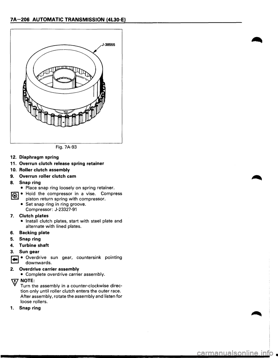
13. Piston (Fig. 7A-92, 7A-93)
Front view
1®..1• Install the inner installer on the drum.
• Pre-install piston into outer installer.
• Install
overrun clutch piston assembly. Use the
outer
installer while pushing piston into drum.
Installer: J-38555
Fig. 7A-92
Page 1078 of 1928
7A-206 AUTOMATIC TRANSMISSION (4L30-E)
Fig. 7A-93
12. Diaphragm spring
11. Overrun clutch release spring retainer
1 0. Roller clutch assembly
9. Overrun roller clutch cam
8. Snap ring
• Place snap ring loosely on spring retainer.
I®J • Hold the compressor in a vise. Compress
piston return spring
with compressor.
• Set snap ring in ring groove.
Compressor: J-23327-91
7. Clutch plates
• Install clutch plates, start with steel plate and
alternate with lined plates.
6. Backing plate
5. Snap ring
4. Turbine shaft
3. Sun gear
r=l • Overdrive sun gear, countersink pointing
t=.l downwards.
2. Overdrive carrier assembly
• Complete overdrive carrier assembly.
\i7 NOTE:
VI Turn the assembly in a counter-clockwise direc
tion
only until roller clutch enters the outer race.
After assembly, rotate the assembly and listen for
loose rollers.
1. Snap ring
•
Page 1079 of 1928
AUTOMATIC TRANSMISSION (4L30-E) 7 A-207
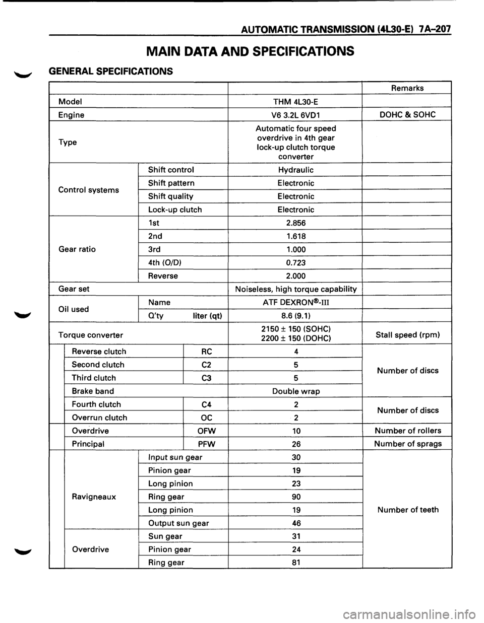
MAIN DATA AND SPECIFICATIONS
GENERAL SPECIFICATIONS
Remarks
Model THM 4L30-E
Engine
V6 3.2L 6VD1 DOHC&SOHC
Automatic four speed
Type overdrive
in 4th gear
lock-up clutch
torque
converter
Shift control Hydraulic
Shift pattern
Electronic Control systems Shift quality Electronic
Lock-up clutch Electronic
1st 2.856
2nd 1.618
Gear ratio
3rd
1.000
4th (0/0) 0.723
Reverse 2.000
Gear set
Noiseless, high torque capability
Name ATF
DEXRON®-m
Oil used O'ty liter (qt) 8.6 (9.1)
Torque
converter 2150 ± 150 (SOHC)
Stall speed (rpm) 2200 ± 150 (OOHC)
Reverse clutch RC 4
Second clutch
C2 5 Number of discs Third clutch C3 5
Brake band
Double
wrap
Fourth clutch C4 2 Number of discs
Overrun clutch oc 2
Overdrive
OFW 10 Number of rollers
Principal
PFW 26 Number of sprags
Input sun gear 30
Pinion gear 19
Long pinion 23
Ravigneaux Ring gear 90
Long pinion 19 Number of teeth
Output sun gear 46
Sun gear 31
Overdrive Pinion gear
24
Ring gear
81
Page 1080 of 1928
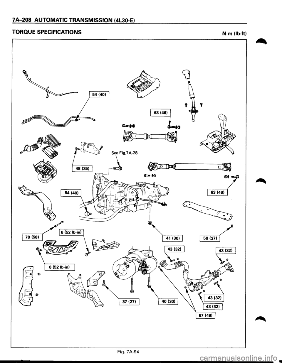
7 A-208 AUTOMATIC TRANSMISSION (4l30-E)
TORQUE SPECIFICATIONS
•
/r6 (52 lb·in)
~-L
~
Fig. 7A-94
N-m (lb-ft)
'
o;
JJI/
~