engine oil ISUZU TROOPER 1995 Workshop Manual
[x] Cancel search | Manufacturer: ISUZU, Model Year: 1995, Model line: TROOPER, Model: ISUZU TROOPER 1995Pages: 1928
Page 678 of 1928
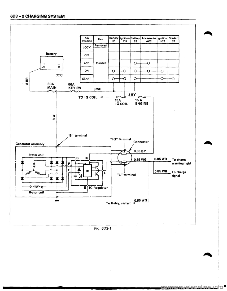
603-2 CHARGING SYSTEM
Battery
+ -...--o ?
,.h,
a: a:l co BOA MAIN . .-. -,., ~
3: co
50 A KEYSW
Key
Position
LOCK
OFF
ACC
ON
START Key
Removed
Inserted
3WB
TO IG COIL
Battery Ignition Battery Accessories Ignition Starter 81 IG1 82 ACC IG2 ST
0 -o
,.... ,....
,.... ,... ,.... ...., ...., ...., ...., ....,
0 ,.... ,.... ,.... 0 ....,
...., ....,
I J
3BY ~ ,.,.
15A 15 A IGCOIL ENGINE
V
"B" termin_a_I _____ _,"IG" terminal
Generator assembly
s_:a_t_er_co __ i_l __ ~~~.-.-~ - Connector
/...-"""\. 0.85BY
B IG
I ~ I ~ A~
-~ ..->--~~ 0.85 WG 0.85 WR To ch arge
' _-: .~:f--<·1'
.~ ~ ~~~~ T ~-r-~ L
. L_ __j
• 1 .... ~ ~ E IC Regulator
L_ Rotor coil ----9---------------'
"L" terminal
warni ng light
0.85WR To ch arge
signal
0.85
WG To Relay, restart
Fig. 603-1
•
Page 689 of 1928
IGNITION SYSTEM 6D4 - 1
SECTION 604
IGNITION SYSTEM
CONTENTS
General Description ...................... .
Diagnosis
................................... .
On-Vehicle Service ....................... .
Spark Plug Wire ....................... .
Spark Plug .............................. . 6D4-1
6D4-2 6D4-3
6D4-3
6D4-3
Electronic Ignition (EI) Assembly ...
Crankshaft Position Sensor
(CKP sensor) ........................ .
Torque Specifications
................ .
Main Data and Specifications
......... . 6D4-5
6D4-5
6D4-6
6D4-7
GENERAL DESCRIPTION
Ignition is done by the Electronic Ignition (EI) that
fires directly the ignition plugs from ignition coils
through spark plug wires without using a distributor.
A pair of ignition coils for the cylinders having differ
ent phases by 360° (No.1 and No.4, No.2 and No.5,
No.3 and No.6) are
fired simultaneously.
Since the cylinder on exhaust stoke requires less
energy to fire its ignition plug, energy from the
ignition coils can be utilized to fire the mating cylin
der on compression stroke. After additional 360°
rotation, respective cylinder stokes are reversed.
TheEl consists of three ignition coils, ignition control
module, crank angle sensor, Engine Control Module
(ECM) and other components.
Module is provided under the ignition coil, connected
with ECM by means of 6-pin connector. The
ignition control module turns on/off the primary
circuit of ignition coils, and also it controls the igni
tion timing at the engine
speed below 538 rpm.
A notch in
the timing disc on the crankshaft activates
the crank angle sensor which then sends information
such as firing order and starting timing of each
ignition coil to the ECM.
Further, the El employs Ignition Control (I C) to control
similar to a distributor system.
By receiving
signals such as crank position, engine
speed, water temperature and Manifold Absolute
Pressure (MAP), the ECM controls the ignition timing.
Page 690 of 1928
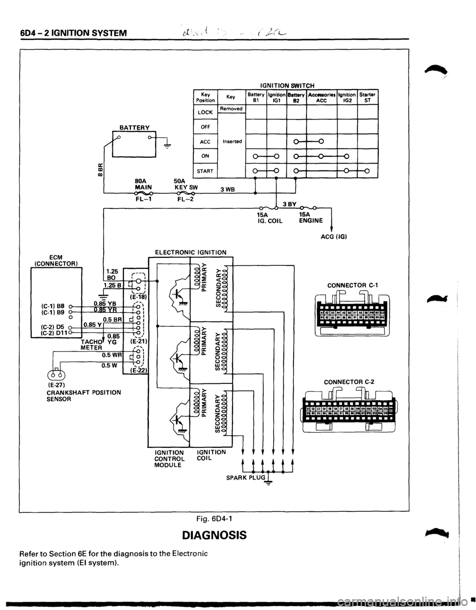
604-2 IGNITION SYSTEM
IGNITION SWITCH
Key
Key Battery
Ignition Battery Acc111ories Ignition
Starter Position 81 IG1 82 ACC IG2 ST
LOCK Removed
BATTERY OFF
/'1 ~ o-
~ Inserted ...... {) ACC ..., -
ON ...... ..... ...... ...... ...... ~ -.....
a: ...... -lXI START Q II) '-' '-' ...., ,_,
BOA 50 A
I 1 MAIN K~YSW 3WB
FL-1 FL-2 3BY -15A 15A IG.COIL ENGINE
ACG (IG)
ELECTRONIC
IGNITION ECM (CONNECTOR) > 1.25 r--""
~~ ~~ BO o""' I
~
1.25 B rrvl -~~ ' f"--~ CONNECTOR C-1
_l_ .... __ .J ~~ c1 mp Shr (E-18)
(C-1) B8 0.85 VB ,, ... , ~~ R!'i YR I I Cl.lo
I !ita lui (C-1) 89 I 0 0.5 BR d 0: IBIBIIIINIBI111Io
(C-2) 05 0.85Y "'I I I > ---(C-2) 011 I
I
)+ 0.85 '-'I a:
~~ ,_, <( TACHO YG (E-21)
~
;;!] METER ,:. .... , a: ~~ 0.5WR q 0! 0... ~~
0.5W I ~$ ... _, ~0 c ( (E-22)
(E-27) CONNECTOR C-2
CRANKSHAFT POSITION .::::> rL
r;::::l enD. .-SENSOR I~ ~~
~ ~ ~~ rt~·· IC4 IT>TiiTiil
f §~
~g l CIJ 0::
·~'l
IGNITION IGNITION CONTROL
COIL MODULE tii1it SPARK PLU
DIAGNOSIS
Refer to Section 6E for the diagnosis to the Electronic
ignition system (EI system).
•
Page 692 of 1928
604-4 IGNITION SYSTEM
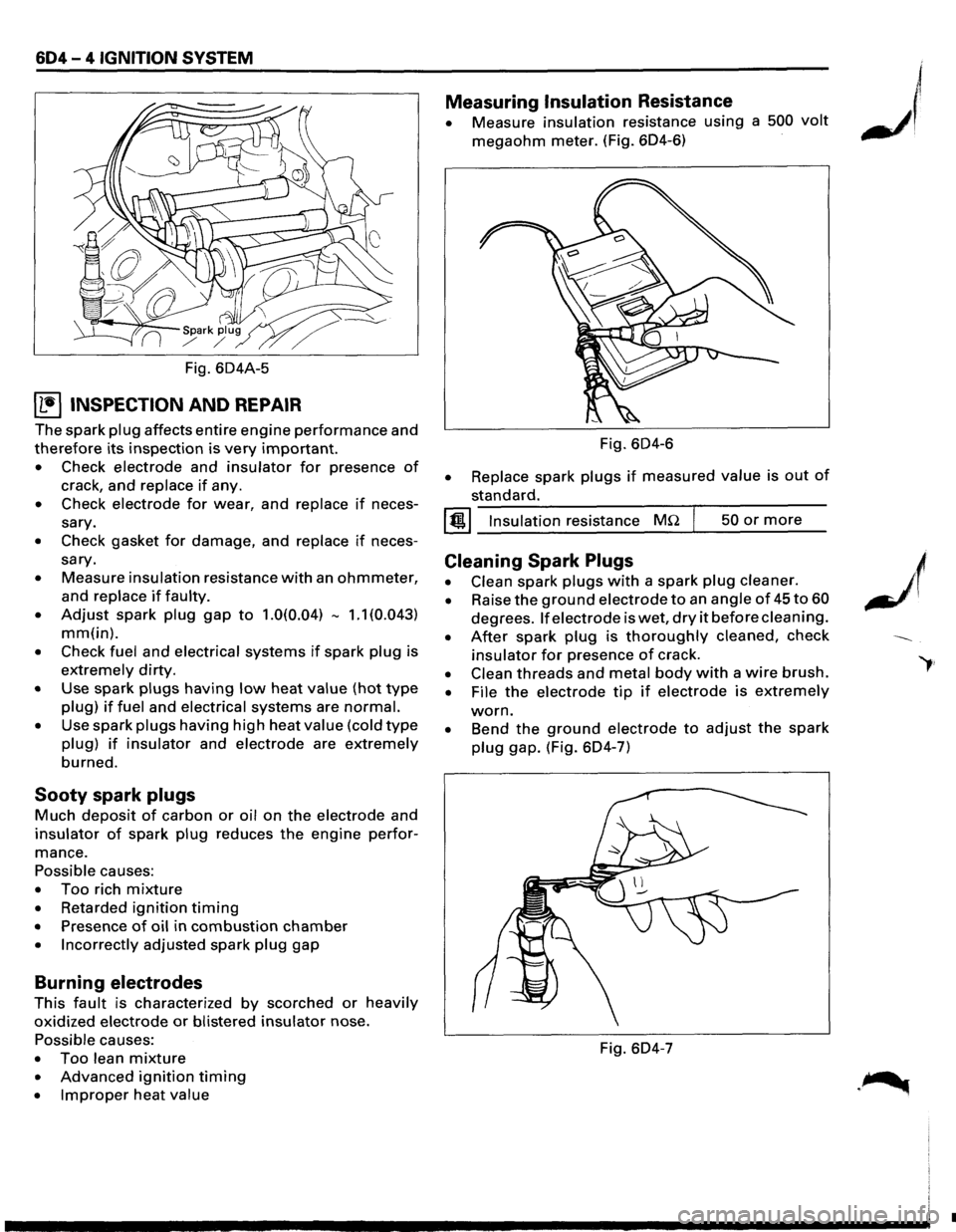
Fig. 604A-5
~ INSPECTION AND REPAIR
The spark plug affects entire engine performance and
therefore its inspection is very important.
• Check electrode and insulator for presence of
crack, and replace if any.
• Check electrode for wear, and replace if neces
sary.
• Check gasket for damage, and replace if neces
sary.
• Measure insulation resistance with an ohmmeter,
and replace if faulty.
• Adjust spark plug gap to 1.0(0.04) -1.1 (0.043)
mm(in).
• Check fuel and electrical systems if spark plug is
extremely dirty.
• Use spark plugs having low heat value (hot type
plug) if fuel and electrical systems are normal.
• Use spark plugs having high heat value (cold type
plug) if insulator and electrode are extremely
burned.
Sooty spark plugs
Much deposit of carbon or oil on the electrode and
insulator of spark plug reduces the engine perfor
mance.
Possible causes:
• Too rich mixture
• Retarded ignition timing
• Presence of oil in combustion chamber
• Incorrectly adjusted spark plug gap
Burning electrodes
This fault is characterized by scorched or heavily
oxidized electrode or blistered insulator nose.
Possible causes:
• Too lean mixture
• Advanced ignition timing
• Improper heat value
Measuring Insulation Resistance
• Measure insulation resistance using a 500 volt
megaohm meter. (Fig. 604-6)
Fig.
604-6
• Replace spark plugs if measured value is out of
standard.
I @!.j Insulation resistance MQ 50 or more
Cleaning Spark Plugs
• Clean spark plugs with a spark plug cleaner.
• Raise the ground electrode to an angle of 45 to 60
degrees. If electrode is wet, dry it before cleaning.
• After spark plug is thoroughly cleaned, check
insulator for presence of crack.
• Clean threads and metal body with a wire brush.
• File the electrode tip if electrode is extremely
worn.
• Bend the ground electrode to adjust the spark
plug gap. (Fig. 604-7)
Fig. 604-7
•
Page 703 of 1928
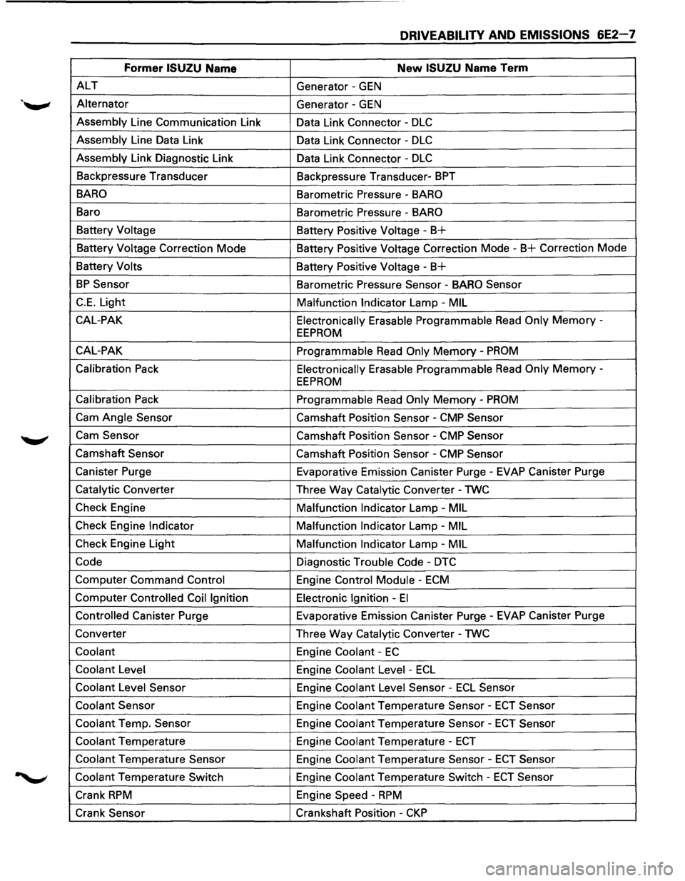
DRIVEABILITY AND EMISSIONS 6E2-7
Former ISUZU Name New ISUZU Name Term
ALT Generator -GEN
Alternator
Generator -GEN
Assembly Line Communication Link
Data Link Connector -DLC
Assembly Line Data Link
Data Link Connector -DLC
Assembly Link Diagnostic Link
Data Link Connector -DLC
Backpressure Transducer
Backpressure Transducer-BPT
BARO Barometric Pressure -BARO
Baro
Barometric Pressure -BARO
Battery Voltage
Battery Positive Voltage-B+
Battery Voltage Correction Mode Battery Positive Voltage Correction Mode -B+ Correction Mode
Battery Volts
Battery
Positive Voltage-B+
BP Sensor Barometric Pressure Sensor -BARO Sensor
C.E. Light
Malfunction Indicator Lamp -MIL
CAL-PAK Electronically
Erasable Programmable Read Only Memory -
EEPROM
CAL-PAK
Programmable Read Only Memory -PROM
Calibration Pack Electronically Erasable Programmable Read Only Memory -
EEPROM
Calibration Pack
Programmable Read Only Memory-PROM
Cam Angle Sensor Camshaft Position Sensor -CMP Sensor
Cam Sensor Camshaft Position Sensor -CMP Sensor
Camshaft Sensor Camshaft Position Sensor -CMP Sensor
Canister Purge Evaporative Emission Canister Purge-EVAP Canister Purge
Catalytic Converter
Three Way Catalytic Converter-TWC
Check Engine
Malfunction
Indicator Lamp -MIL
Check Engine Indicator Malfunction Indicator Lamp -MIL
Check Engine Light
Malfunction Indicator Lamp-MIL
Code Diagnostic Trouble Code -DTC
Computer Command Control Engine Control Module -ECM
Computer Controlled Coil Ignition Electronic Ignition -El
Controlled Canister Purge Evaporative Emission Canister Purge-EVAP Canister Purge
Converter Three Way Catalytic Converter -TWC
Coolant Engine Coolant -EC
Coolant Level
Engine Coolant Level -ECL
Coolant Level Sensor Engine Coolant Level Sensor -ECL Sensor
Coolant Sensor Engine Coolant Temperature Sensor -ECT Sensor
Coolant Temp. Sensor Engine Coolant Temperature Sensor-ECT Sensor
Coolant Temperature Engine Coolant Temperature -ECT
Coolant Temperature Sensor Engine Coolant Temperature Sensor-ECT Sensor
Coolant Temperature Switch Engine Coolant Temperature Switch -ECT Sensor
Crank RPM Engine Speed -RPM
Crank Sensor Crankshaft Position-CKP
Page 720 of 1928
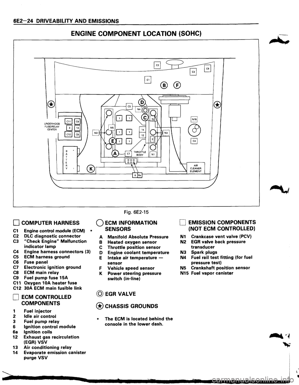
6E2-24 DRIVEABILITY AND EMISSIONS
ENGINE COMPONENT LOCATION (SOHC)
UNDERHOOD
FUSE/RELAY
CENTER
8 A
T
T
E
R y
0 COMPUTER HARNESS
C1 Engine control module (ECM) *
C2 DLC diagnostic connector
C3 "Check Engine" Malfunction
indicator lamp
C4 Engine harness connectors (3)
C5 ECM harness ground
C6 Fuse panel
C7 Electronic ignition ground
CS ECM main relay
C9 Fuel pump fuse 15A
C11 Oxygen 1 OA heater fuse
C12 30A ECM main fusible link
0 ECM CONTROLLED
COMPONENTS
1 Fuel injector
2 Idle air control
3 Fuel pump relay
6 Ignition control module
6a Ignition coils
12 Exhaust gas recirculation
(EGR) VSV
13 Air conditioning relay
14 Evaporate emission canister
purge VSV
Fig. 6E2-15
Q ECM INFORMATION
SENSORS
®
A Manifold Absolute Pressure
B Heated oxygen sensor
C Throttle position sensor
D Engine
coolant temperature
E Intake air temperature -
sensor
F Vehicle speed sensor
K Power steering pressure
switch (in-line)
@ EGRVALVE
@CHASSIS GROUNDS
* The ECM is located behind the
console in the lower dash.
®
[::::J EMISSION COMPONENTS
(NOT
ECM CONTROLLED)
N1 Crankcase vent valve (PCV)
N2 EGR valve back pressure
transducer
N3 Spark plugs
N4 Fuel rail test fitting (for fuel
pressure test)
N5 Crankshaft position sensor
N15 Fuel vapor canister
Page 721 of 1928
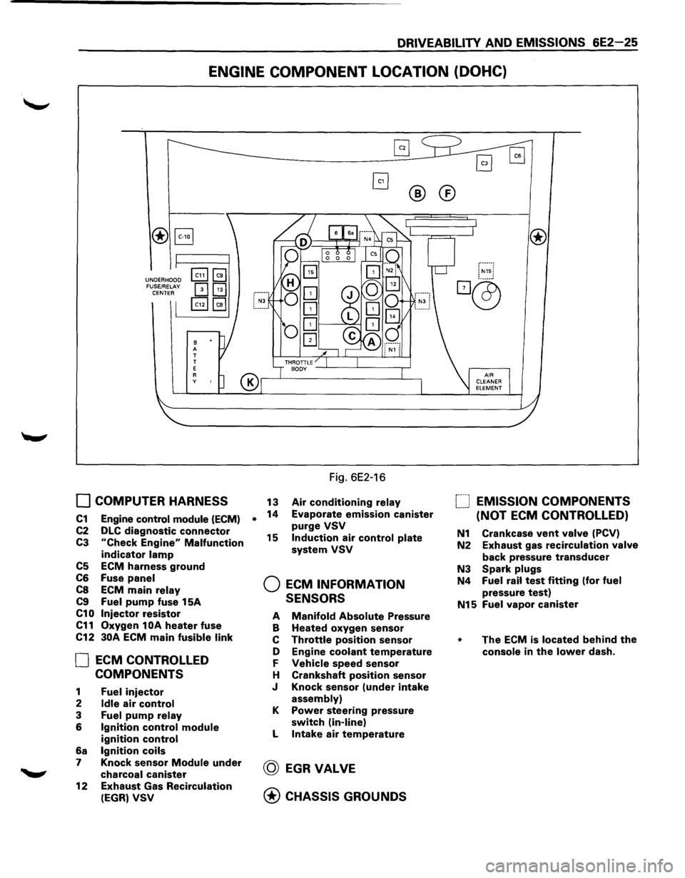
DRIVEABILITY AND EMISSIONS 6E2-25
ENGINE COMPONENT LOCATION (DOHC)
®B
UNDERHOOD FUSE/RELAY CENTER
B A T
T
E
A y
0 COMPUTER HARNESS
C1 Engine control module (ECM)
C2 DLC diagnostic connector
C3 "Check Engine" Malfunction
indicator lamp
C5 ECM harness ground
C6 Fuse panel
C8 ECM main relay
C9 Fuel pump fuse 15A
C10 Injector resistor
C11 Oxygen 1 OA heater fuse
C12
30A ECM main fusible link
0 ECM CONTROLLED
COMPONENTS
1 Fuel injector
2 Idle air control
3 Fuel pump relay
6 Ignition control module
ignition control
6a Ignition coils
7 Knock sensor Module under
charcoal canister
12
Exhaust Gas Recirculation
(EGR) VSV
*
®®
Fig. 6E2-16
13 Air conditioning relay
14 Evaporate emission canister
purge VSV
15 Induction air control plate
system VSV
Q ECM INFORMATION
SENSORS
A Manifold Absolute Pressure
B Heated oxygen sensor
c Throttle position sensor
D Engine
coolant temperature
F Vehicle speed sensor
H Crankshaft
position sensor
J Knock sensor
(under intake
assembly)
K Power steering pressure
switch (in-line)
L Intake air temperature
@ EGRVALVE
@ CHASSIS GROUNDS
f----1 EMISSION COMPONENTS !.-----' (NOT ECM CONTROLLED)
N1 Crankcase vent valve (PCV)
N2 Exhaust gas
recirculation valve
back pressure transducer
N3 Spark plugs
N4 Fuel rail test fitting (for fuel
pressure test)
N15 Fuel vapor canister
* The ECM is located behind the
console in the lower dash.
Page 722 of 1928
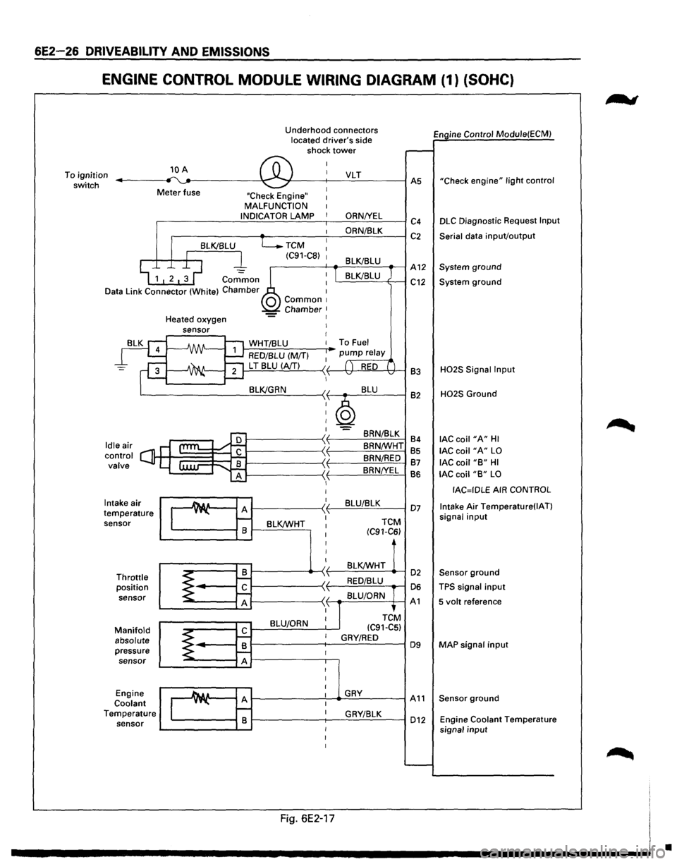
6E2-26 DRIVEABILITV AND EMISSIONS
ENGINE CONTROL MODULE WIRING DIAGRAM (1) (SOHC}
To ignition
switch 10 A
Meter fuse Underhood
connectors
located driver's side
shock tower
"Check Engine" MALFUNCTION
.-----------..:.:.1 N.:.:D:..:.IC=A~T~O:..:.R.:....=:.LA..::.M.:..::P:..___-,--___.:O:..:.R.:.:.N::.._IY.....:E:..:L=----1 c4
.------~~----~~O:..:R:..:N/~8~L=-=K--~ C 2
TCM
(C91-C8)
Engine Control Module(ECM)
"Check
engine" light control
DLC Diagnostic Request Input
Serial
data inpuVoutput
.--------f---+-....::...::;_;__=---_-1 A 12 System ground
Common
Data Link Connector (White) Chamber L.....::.=::....=..:=-=----+---1 C12 System ground
Intake air
temperature sensor
Throttle position
sensor
Manifold absolute pressure sensor
Engine
Coolant Temperature sensor Heated
oxygen
J-,.:..:W:.:..H.:..:T.:.:I8:..:L:.:U:......__ __ ....-To Fuel
RED/BLU (M/T)
1---=-'L T'-.!8~L:!:U'--l(.::::A/T!....!...!....) ---< f------lt+-~!,!..._'H---1 83
BRN/8LK
84
8RN/WHT 85
BRN/RED 87
8RN!YEL
BS
1---------~~~B~L~U~/8~L~K~--I 07
BLK/WHT
TCM
(C91-C6)
BLK/WHT 1------------4>---< t-----=~:..:.:..:_.:..:_ ....... -1 02
1-----------~ f----'-=-'-==--....-1 06
1-----------~ f--.-::..:=.=.:....=..c~-+--1 A 1
BLU/ORN
H02S Signal Input
H02S Ground
lAC coil "A" HI
lAC coil "A" LO
lAC coil "B" HI
lAC coil "B" LO
IAC=IDLE AIR CONTROL
Intake
Air Temperature(IAT)
signal input
Sensor ground
TPS signal input
5 volt reference
MAP
signal input
1---------'----...._.G:=.:..:.RY-=--------1 A 11 Sensor ground
1-------;---.:::G:..:R_;_YI:...::8:..:L::..:K:__---I 012 Engine Coolant Temperature
signal input
Fig. 6E2-17
•
Page 725 of 1928
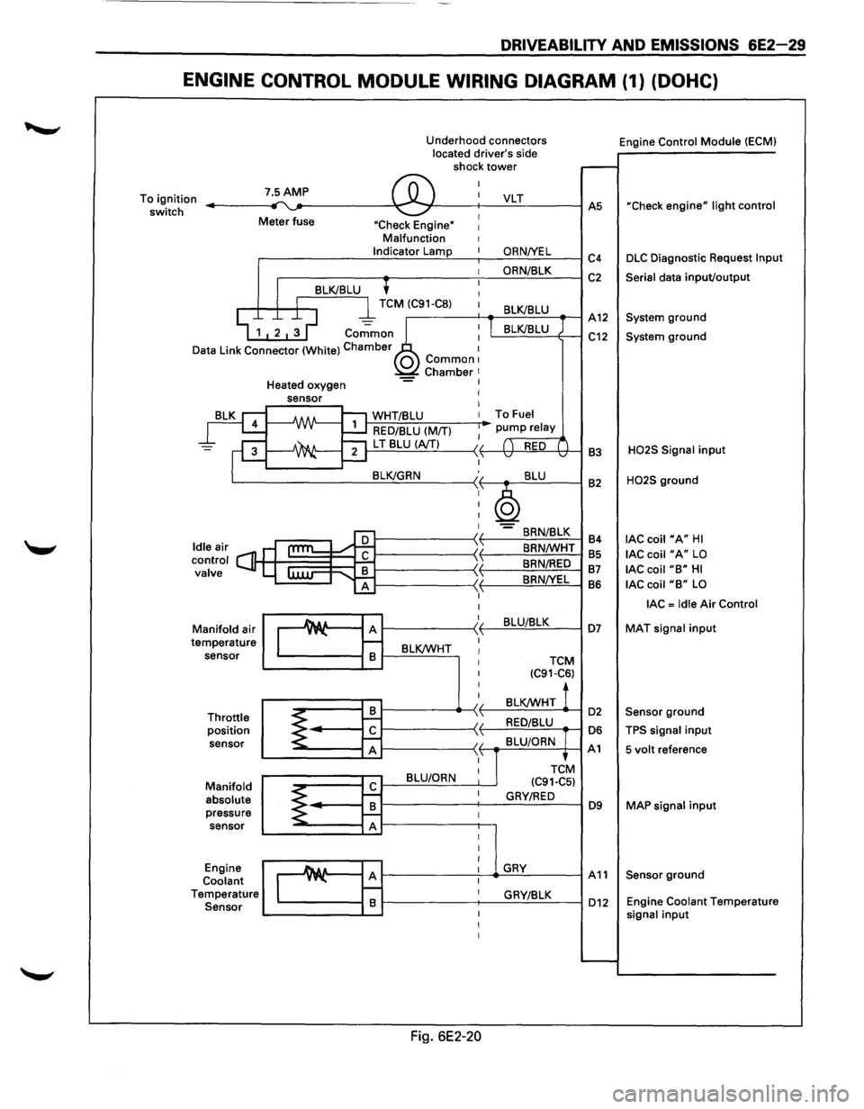
DRIVEABILITY AND EMISSIONS 6E2-29
ENGINE CONTROL MODULE WIRING DIAGRAM (1) (DOHC)
Underhood connectors
located driver's side
shock
tower
To ignition
switch 7.5AMP ,.... ~ ®
I
I
Meter fuse I "Check Engine" I Malfunction I Indicator Lamp I
I
'
I 8LK/8LU I
D
I l TCM (C91-C8) 1
~ 1 2 ~ ~ co.;;mo~~ : ata Link Connector (White) Chamber 1 0 Common1 Chamber 1 Heated oxygen -= I
rg
=F
leair s ontrol C] alve
ld c v
M
te anifold
air
mperature sensor
Throttle position sensor
Manifold absolute pressure sensor
Engine
Coolant
T emperature
Sensor
sensor I
I
-A/IN-1:'1 WHT/8LU I
~ RED/8LU (M/TI I
~ ""21 L T 8LU (A/TI II ....::....1 ,1,
8LK/GRN :,
I
I
I
I
cam l:
I
I
Au A )I y"-\1 r--
8 8LK/WHT I I
I
I
I
8 ~ 1--II
~ r£ \ 'I A ,1,
8LU/ORN I
r£ ~ I
8 ~ f--I A I
I
I
_A& a A I y"-I r--I 8 I
I
I
Fig. 6E2-20
VLT
ORNNEL
ORN/8LK
8LK/8LU
I 8LK/8LU
To Fuel
pump relay
( ) RED ( v v
8LU
~ -8RN/8LK
8RN/WHT
8RN/RED
8RNNEL
8LU/8LK
TCM (C91-C6)
8LK/WHT !
RED/8LU
8LU/ORN
TCtM
(C91-C5)
GRY/RED
GRY
GRY/8LK Engine
Control
Module (ECMI
.-----
AS "Check engine" light control
C4 DLC Diagnostic Request lnpu
C2 Serial data input/output
A12 System ground
C12 System ground
83
H02S Signal input
82 H02S ground
84
lAC coil "A" HI
85 lAC coil "A" LO
87 lAC coil "8" HI
86 lAC coil "8" LO
lAC = Idle Air Control
D7 MAT signal input
D2 Sensor ground
D6 TPS signal input
A1 5 volt reference
D9 MAP signal input
A11 Sensor ground
D12 Engine Coolant Temperatur e signal input
......__
Page 729 of 1928
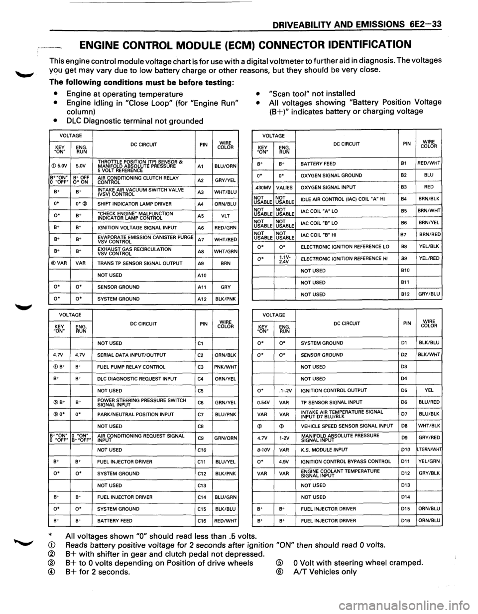
DRIVEABILITY AND EMISSIONS 6E2-33
ENGINE CONTROL MODULE (ECM) CONNECTOR IDENTIFICATION
This engine control module voltage chart is for use with a digital voltmeter to further aid in diagnosis. The voltages
you get may vary due to low battery charge or other reasons, but they should be very close.
The following conditions must be before testing:
• Engine at operating temperature • "Scan tool" not installed
•
Engine idling in "Close Loop" (for "Engine Run"
column) •
All voltages showing "Battery Position Voltage
(8+)" indicates battery or charging voltage
•
DLC Diagnostic terminal not grounded
VOLTAGE VOLTAGE
DC CIRCUIT PIN WIRE
KEY ENG. COLOR
"ON" RUN
DC CIRCUIT PIN WIRE
KEY ENG. COLOR "ON" RUN
ID 5.0V 5.0V THROTILE
POSITION ~TP~ SENSOR & MANIFOLD ABSOLUT P ESSURE A1 BLU/ORN 8+ B+ BATIERY FEED B1 RED/WHT
5 VOLT REFERENCE B+"ON" B+ OFF AIR CONDITIONING CLUTCH RELAY A2 GRY/YEL 0 "OFF" 0* ON
CONTROL o• o• OXYGEN SIGNAL GROUND 82 BLU
B+ s+ INTAKE
AIR VACUUM SWITCH VALVE A3 WHT/BLU (VSV) CONTROL
o• O*® SHIFT INDICATOR LAMP DRIVER A4 ORN/BLU .430MV
VALlES OXYGEN
SIGNAL INPUT
B3 RED
NOT NOT
IDLE AIR CONTROL (lAC) COIL "A" HI B4 8RN/BLK USABLE
USABLE
o• B+ "CHECK ENGINE" MALFUNCTION A5 VLT INDICATOR LAMP CONTROL
B+ B+ IGNITION VOLTAGE SIGNAL INPUT
AS RED/GRN
NOT NOT
lAC COIL "A" LO B5 8RN/WHT USABLE USABLE
NOT NOT
lAC COIL
"B" LO B6 BRN/YEL USABLE
USABLE
B+ B+ EVAPORATE EMISSION CANISTER PURGE A7 WHT/RED VSVCONTROL NOT
NOT
lAC COIL "B" HI B7 BRN/RED USABLE
USABLE
B+ 8~ EXHAUST GAS RECIRCULATION AS WHT/GRN VSV CONTROL
@VAR VAR TRANS TP SENSOR SIGNAL OUTPUT A9 8RN
o• o• ELECTRONIC IGNITION REFERENCE LO 88 YEL/BLK
o• 1.1V-ELECTRONIC
IGNITION REFERENCE HI B9 YEL/RED
2.4V
NOT USED B10
NOT USED
A10
NOT USED
B11 o• o• SENSOR GROUND A11 GRY
NOT USED B12 GRY/BLU o• o• SYSTEM
GROUND A12 8LK/PNK
VOLTAGE
VOLTAGE
DC CIRCUIT PIN WIRE
KEY ENG. COLOR DC CIRCUIT PIN WIRE
KEY ENG. COLOR "ON" RUN "ON" RUN
NOT USED C1 o• o• SYSTEM GROUND D1 BLK/BLU
4.7V 4.7V
SERIAL DATA INPUT/OUTPUT C2 ORN/8LK o• 0* SENSOR GROUND D2 BLK/WHT
@) B+ B+ FUEL PUMP RELAY CONTROL C3 PNK/WHT NOT USED D3
B+ B+ DLC DIAGNOSTIC REQUEST INPUT C4 ORN/YEL NOT USED D4
NOT USED C5 o• .1·.2V IGNITION
CONTROL OUTPUT D5 YEL
@B+ B+ POWER STEERING PRESSURE SWITCH C6 GRN/YEL SIGNAL INPUT 0.54V VAR
TP SENSOR
SIGNAL INPUT D6 BLU/RED
@O* o• PARK/NEUTRAL POSITION
INPUT C7 BLU/PNK VAR
VAR INTAKE AIR TEMPERATURE SIGNAL D7 BLU/BLK INPUT D7 BLU/BLK
NOT USED CB ® ® VEHICLE SPEED SENSOR
SIGNAL INPUT D8 WHT/BLK
B+"ON" 0 "ON" AIR CONDITIONING REQUEST SIGNAL C9 GRN/ORN
0 "OFF" B+"OFF"
INPUT 4.7V 1-2V MANIFOLD ABSOLUTE PRESSURE D9 GRY/RED SIGNAL
INPUT
NOT USED
C10 8-10V
VAR K.S.
MODULE INPUT D10 LTGRN/WHT
B+ B+ FUEL INJECTOR
DRIVER C11 BLU/YEL o• 4.9V IGNITION CONTROL BYPASS CONTROL D11 YELIGRN
o• o• SYSTEM GROUND
C12 BLK/PNK VAR VAR ENGINE COOLANT TEMPERATURE
D12 GRY/BLK SIGNAL
INPUT
NOT USED
C13 NOT USED D13
B+ 8+
FUEL INJECTOR DRIVER C14 BLU/GRN NOT USED D14
o• o• SYSTEM GROUND
C15 BLK/BLU B+ B+ FUEL INJECTOR DRIVER D15 ORN/BLU
8+ B+ BATIERY FEED C16 RED/WHT B+ 8+
FUEL INJECTOR DRIVER D16 ORN/8LU
* All voltages shown "0" should read less than .5 volts.
Reads battery positive voltage for 2 seconds after ignition "ON" then should read 0 volts. CD
®
® @
B+ with shifter in gear and clutch pedal not depressed.
B+ to 0 volts depending on Position of drive wheels
B+ for 2 seconds.
@
®
0 Volt with steering wheel cramped.
A/T Vehicles only