engine oil ISUZU TROOPER 1995 Workshop Manual
[x] Cancel search | Manufacturer: ISUZU, Model Year: 1995, Model line: TROOPER, Model: ISUZU TROOPER 1995Pages: 1928
Page 1506 of 1928
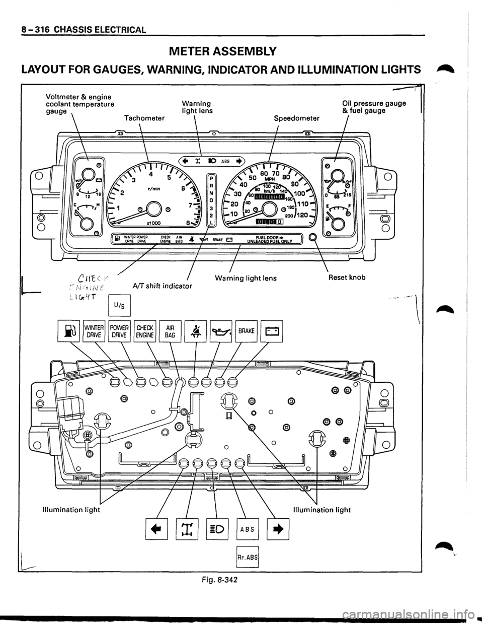
8-316 CHASSIS ELECTRICAL
METER ASSEMBLY
LAYOUT FOR GAUGES, WARNING, INDICATOR AND ILLUMINATION LIGHTS .~
L
Voltmeter & engine
coolant temperature
gauge
B
Warning light lens
0
ClEO< AIR Et.llf>E BAG
NT shift indicator
Fig. 8-342
@ @
0 0
Oil pressure gauge & fuel gauge
..
Page 1507 of 1928
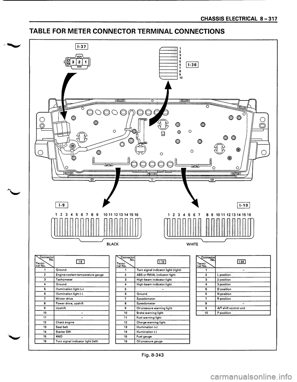
CHASSIS ELECTRICAL 8-317
TABLE FOR METER CONNECTOR TERMINAL CONNECTIONS
~-""""""', 1----""'12 1----""'1! 6 1----l 6 [Iill
1----""'1 ~ 9 1---""'l,o
®
0 0
0
® @
0 0 ~
~m© © © © ©'--m ~~0
0 !III
1 2 3 4 5 6 7 8 9 1011 1213141516 1 2 3 4 56 7 8 9 10111213141516
w~~~~~~~~ ~~~~~~m rn~~~~~~ ~~nn~~m
~ I J BLACK WHITE
~r o. DTI -na No. ~
. IJJ:Q] -
. ~ [ill] . -. 1 Ground 1 Turn
signal indicator light (right)
1 -2 Engine coolant temperature gauge 2 ABS or RWAL indicator light 2 L
position
3 Tachometer 3 High-beam indicator light 3 2 position 4
Ground
4 High-beam
indicator light 4 3 position 6 Illumination light (+I 5 -5 D position
6 Illumination light(-) 6 Ground 6 N position 7 Winter drive 7 Speedometer 7 R position 8 Power drive, upshift 8 Speedometer 8 -9 Upshift 9 Oil pressure warning light 9 AfT shift control unit 10 -10 Brake warning light 10 P position 11 -11 Fuel warning light 12 Check engine 12 Charge warning light 13 Seat belt 13 Illumination (+) 14 StarterSW 14 Illumination (-) 15 4WD 15 Fuel gauge 16 Turn signal indicator light (left) 16 Oil pressure gauge
Fig. 8-343
Page 1511 of 1928
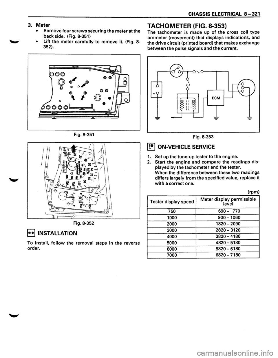
3. Meter
• Remove four screws securing the meter at the
back side. (Fig.
8-351)
• Lift the meter carefully to remove it. (Fig. 8-
352).
0
q;J"' 0
0 0 0,
0 0
0 I
Fig. 8-351
Fig. 8-352
E) INSTALLATION
00
0
To install, follow the removal steps in the reverse
order.
CHASSIS ELECTRICAL 8-321
TACHOMETER (FIG. 8-353)
The tachometer is made up of the cross coil type
ammeter (movement) that displays indications, and
the drive circuit (printed board)
that makes exchange
between the
pulse signals and the current.
Fig.
8-353
(1!1 ON-VEHICLE SERVICE
1. Set up the tune-up tester to the engine.
2. Start the engine and compare the readings dis
played by the tachometer and the tester.
When the difference between these
two readings
differs
largely from the specified value, replace it
with a correct one.
(rpm)
Tester
display speed Meter
display permissible level
750 690-770
1000
900-1060
2000 1820-2090
3000 2820-3120
4000 3820-4180
5000 4820-5180
6000 5820-6180
7000 6820-7180
Page 1515 of 1928
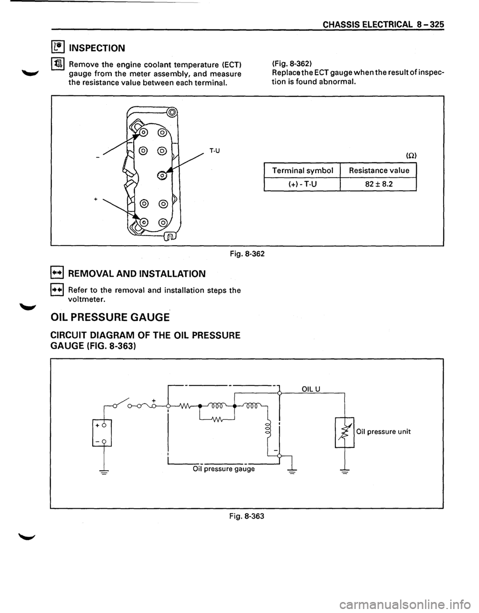
~ INSPECTION
131 Remove the engine coolant temperature (ECT)
gauge from the meter assembly, and measure
the resistance value between each terminal.
T·U
+
Fig. 8-362
E) REMOVAL AND INSTALLATION
1••1 Refer to the removal and installation steps the
voltmeter.
OIL PRESSURE GAUGE
CIRCUIT DIAGRAM OF THE OIL PRESSURE
GAUGE (FIG. 8-363)
CHASSIS ELECTRICAL 8 -325
(Fig. 8-362)
Replace the
ECT gauge when the result of inspec
tion is found abnormal.
(Q)
Terminal symbol Resistance
value
(+)-T·U 82 ± 8.2
OILU
Oil pressure unit
,______ _ __ ___.
Oil pressure gauge
Fig. 8-363
Page 1521 of 1928
![ISUZU TROOPER 1995 Workshop Manual OIL PRESSURE UNIT
(1!] INSPECTION
Measure the resistance value ofthe oil pressure unit
with the circuit tester. (Fig. 8-377)
Replace the
unit when the result of inspection is found
abnorm](/img/61/57183/w960_57183-1520.png "ISUZU TROOPER 1995 Workshop Manual OIL PRESSURE UNIT
(1!] INSPECTION
Measure the resistance value ofthe oil pressure unit
with the circuit tester. (Fig. 8-377)
Replace the
unit when the result of inspection is found
abnorm")
OIL PRESSURE UNIT
(1!] INSPECTION
Measure the resistance value ofthe oil pressure unit
with the circuit tester. (Fig. 8-377)
Replace the
unit when the result of inspection is found
abnormal.
Pressure
(kPa)
Resistance value (Q)
Fig. 8-377
OIL PRESSURE SWITCH
(1!] INSPECTION
98 981
81 30
I~~ Check the continuity between the switch termi
nal and the body ground with the engine at idle.
(Fig. 8-378)
Replace the switch when the result
of inspection
is
found abnormal.
Fig. 8-378
CHASSIS ELECTRICAL 8-331
(1!] CIRCUIT INSPECTION (FIG. 8-379)
Fig. 8-379
1. Start the engine.
2. When disconnecting the oil pressure switch con
nector then connecting the harness side connec
tor to the ground, check to see if the oil pressure
warning light lights up.
When the
light will not light up, check the circuit
between the meter and the oil pressure switch,
and repair
an open circuit if necessary.
FUEL TANK UNIT
The tank unit varies the internal resistance according
to the float position (fluid level) to operate the fuel
meter needle.
It is also designed
to warn the driver of low fuel level
by illuminating the fuel warning light. (Fig. 8-380)
Fig. 8-380
Page 1632 of 1928
9J-8 Supplemental Restraint System
DEFINITIONS
AIR BAG -An inflatable cloth cushion designed to
deploy in certain frontal crashes. It supplements the
protection offered by the seat belts by distributing the
impact load more evenly over the vehicle occupant's
head and torso.
ASYNCHRONOUS -Performed in a non-periodic
fashion,i.e.no defined time or interval.
B+-Battery voltage, the voltage available at the battery
at the time of the indicated measurement. With the key
"ON" and the engine not running, the system voltage will
likely be between 12 and 12.5 volts. At idle the voltage
may be 14 to 16 volts. The voltage could be as low as 1
0
volts during engine cranking.
BULB
CHECK-The DERM will cause the "AIR BAG"
warning lamp to flash seven times and then go "OFF"
whenever the ignition switch transitions to the RUN
position from any other ignition switch position and no
malfunctions are detected.
"CONTINUOUS MONITORING"-Tests performed by
the DERM on the
SRS every 1 00 milliseconds while
"Ignition
1" voltage is in the normal operating voltage
range at the DERM.
DATA LINK CONNECTOR(DLC)-Formerly "ALDL'', a
connector which allows communication with an
off-board computer, such as a scan
tool.
DATUM LINE-A base line parallel to the plane of the
underbody or frame from which all vertical
measurements originate.
DEPLOY-To inflate the air bag.
DEPLOYMENT
LOOPS - The circuits which supply
current to the inflator modules to deploy the air bag.
DERM -Diagnostic
energy reserve module which
provides reserve energy to the deployment loops and
performs diagnostic monitoring of
all SRS components.
DIAGNOSTIC TROUBLE CODE(DTC) -Formerly
"Code,"a numerical designator used by the DERM to
indicate specific
SRS malfunctions.
DRIVER CURRENT SOURCE-An output of the DERM
which injects current into the driver inflator module circuit
during the "Initiator Assembly Resistance
Test."
DRIVER INFLATOR
MODULE-An assembly located in
the steering wheel hub consisting of an inflatable air bag,
an inflator and an initiator.
DUAL
POLE ARMING SENSOR-A sensor on the high
side(power side) of the deployment loops that is
calibrated to supply voltage to the inflator modules when
the vehicle velocity changes are severe enough to
warrant arming of the air bags in preparation for
deployment.
EEPROM -Electrically Erasable Programmable Read ~
Only Memory. Memory which retains its contents when
power
is removed from the DERM.
FORWARD LH DISCRIMINATING SENSOR-A sensor
on the low side(ground side) of the deployment loops
which is calibrated to ground the inflator modules when
the vehicle velocity changes are severe enough to
warrant deployment of the air bags.
FORWARD RH DISCRIMINATING SENSOR-A sensor
on the low side(ground side) of the deployment loops
which
is calibrated to ground the inflator modules when
the vehicle velocity changes are severe enough
to
warrant deployment of the air bag.
FORWARD LH SENSOR Eng-Room HARNESS-An
assembly of two correct carrying wires which connects
the Forward
LH discriminating sensor to SRS harness.
FORWARD RH SENSOR Eng-Room HARNESS
JUMPER-An assembly of two current carrying wires
which connects the Forward
RH discriminating sensor to
the
SRS harness.
HIGHER PRIORITY FAULT-Each diagnostic trouble
code
is assigned a priority based on the detectability with
other DTCs present. The priority corresponds to the
detectability of the malfunction ONLY, and does NOT
relate to the criticality of the malfunction with respect to ~
deployment or non-deployment under any given
condition.
IGNITION CYCLE -The voltage at the PERM "Ignition
1"
inputs, with ignition switch "ON," is within the normal
operating voltage range for at least ten seconds before
turning ignition switch
"OFF."
IGNITION1
-A battery voltage(B+)circuit which is only
powered with the ignition switch in the RUN,BULB
TEST,or START positions.
INITIATOR-The electrical component inside the inflator
module which, when sufficient current flows, sets off the
chemical reaction that inflates the air bag.
"INITIATOR ASSEMBLY RESISTANCE TEST"-Tests
performed once each ignition cycle when no
malfunctions are detected during "Turn-ON" or
"Continuous Monitoring." This test checks for the correct
DERM configuration for the vehicle, shorts to
"Ignition 1"
in the deployment loops, high resistance or opens in the
"Driver
Side High," "Driver Side Low," "Passenger Side
High"
and "Passenger Side Low" circuits and measures
the resistance of the inflator assembly consisting of: 1)
Initiators, 2) SRS coil assembly(driver side only), 3)
Connectors and associated wiring.
NORMAL OPERATING VOLTAGE RANGE-The ~
voltage measured between the DERM "Ignition 1" ·
terminals and "Ground" terminals is between 7.25 and 16
volts.
•
Page 1751 of 1928
Supplemental Restraint System 9J-127
SRS COIL ASSEMBLY
WARNING: SAFETY PRECAUTIONS MUST BE FOLLOWED WHEN HANDLING A DEPLOYED INFLATOR
MODULE{AIR
BAG). AFTER DEPLOYMENT, THE INFLATOR MODULE{AIR BAG) SURFACE MAY CONTAIN A
SMALL AMOUNT OF SODIUM HYDROXIDE, A BY-PRODUCT OF THE DEPLOYMENT REACTION, THAT IS
IRRITATING TO
THE SKIN AND EYES. MOST OF THE POWDER ON THE INFLATOR MODULE (AIR BAG )IS
HARMLESS.
AS A PRECAUTION, WEAR GLOVES AND SAFETY GLASSES WHEN HANDLING A DEPLOYED
INFLATOR MODULE {AIR BAG ), AND WASH YOUR HANDS WITH MILD SOAP AND WATER AFTERWARDS.
WARNING: WHEN CARRYING A LIVE INFLATOR MODULE {AIR BAG ), MAKE SURE THE BAG AND TRIM
COVER
ARE POINTED AWAY FROM YOU. NEVER CARRY INFLATOR MODULE {AIR BAG )BY THE WIRES OR
CONNECTOR ON
THE UNDERSIDE OF MODULE. IN THE CASE OF AN ACCIDENTAL DEPLOYMENT, THE BAG
WILL THEN DEPLOY WITH MINIMAL CHANCE OF INJURY. WHEN PLACING A LIVE INFLATOR MODULE (AIR
BAG ) ON A BENCH OR OTHER SURFACE, ALWAYS FACE BAG AND TRIM COVER UP, AWAY FROM THE
SURFACE. NEVER REST A STEERING COLUMN ASSEMBLY ON THE STEERING WHEEL WITH THE INFLATOR
MODULE (AIR BAG) FACE DOWN AND COLUMN VERTICAL. THIS IS NECESSARY SO THAT A FREE SPACE
IS PROVIDED TO
ALLOW THE INFLATOR MODULE { AIR BAG ) TO EXPAND IN THE UNLIKELY EVENT OF
ACCIDENTAL
DEPLOYMENT. OTHERWISE, PERSONAL INJURY COULD RESULT.
NOTE:
In the event deployment has occurred, inspect coil assembly wire for any signs of scorching, melting or any
other damage due to excessive heat.
If the coil has been damaged, replace it.
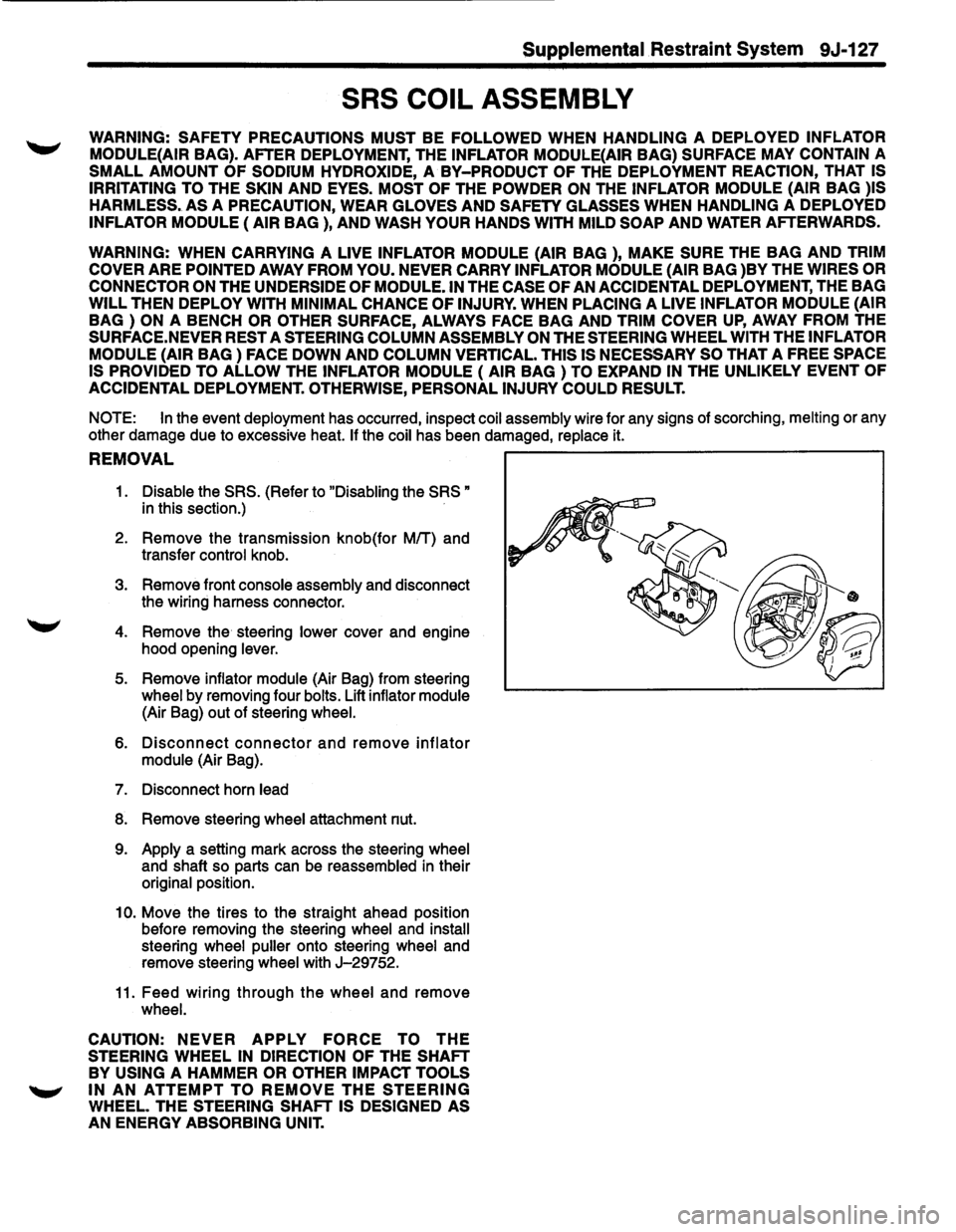
REMOVAL ~------------------------------------------,
1. Disable the SRS. (Refer to "Disabling the SRS"
in this section.)
2. Remove the transmission knob(for
MIT) and
transfer
control knob.
3. Remove front console assembly and disconnect
the wiring harness connector.
4. Remove the steering lower cover and engine
hood opening
lever.
5. Remove inflator module (Air Bag) from steering
wheel by removing four bolts. Lift inflator module
(Air Bag) out of steering wheel.
6. Disconnect connector and remove inflator
module (Air Bag).
7. Disconnect horn lead
8. Remove steering wheel attachment nut.
9. Apply a setting mark across the steering wheel
and shaft so parts can be reassembled in their
original position.
10. Move the tires to the straight ahead position
before removing the steering
wheel and install
steering wheel puller onto steering wheel and
remove steering
wheel with J-29752.
11. Feed wiring through the wheel and remove
wheel.
CAUTION:
NEVER APPLY FORCE TO THE
STEERING WHEEL IN DIRECTION OF THE SHAFT
BY USING A HAMMER OR OTHER IMPACT TOOLS
~ IN AN ATTEMPT TO REMOVE THE STEERING
WHEEL. THE STEERING SHAFT IS DESIGNED AS
AN ENERGY ABSORBING UNIT.
Page 1752 of 1928
9J-128 Supplemental Restraint System
12. Remove steering column cover.
13. Disconnect the wiring harness connectors ~
located base of steering column.
14. Remove the combination switch assembly with
SRScoil.
NOTE: SRS
coil is a part of combination switch
assembly, which
cannot be replaced individually.
Therefore, be sure not to remove the
SRS coil from the
combination switch assembly.
INSTALLATION
1. Install the combination switch assembly with
SRScoil.
2. Connect the wiring harness connector located In
base of steering column.
3. Turn the SRS coil clockwise to full, return about
3 turns and align the neutral mark.
CAUTION: WHEN TURNING THE SRS COIL
CLOCKWISE TO FULL, STOP TURNING IF
RESISTANCE IS FELT. FORCED FURTHER
TURNING MAY CAUSE DAMAGE TO THE CABLE IN
THE SRS COIL.
4. Install steering column cover.
CAUTION: WHEN INSTALLING THE STEERING
COLUMN COVER, BE SURE TO WIRE (THROUGH ~
EACH HARNESS) AS ILLUSTRATED SO THAT THE
HARNESSES OF STARTER SWITCH,COMBINATION
SWITCH
AND SRS COIL MAY NOT CATCH WIRING.
5. Install the steering wheel and align the setting
marks.
6. Tighten the steering fixing nut to the specified
torque.
Torque : 34N·m(25 lb·ft.).
7. Connect horn lead connector.
8. Connect inflator module to 2-way yellow wiring
harness connector.
9. Install inflator module into steering wheel and
torque fasteners.
NOTE: Always replace inflator module {Air Bag)
fasteners with new fasteners. Never reuse old fasteners.
Torque: 8N·m(69 lb·ln.)
10. Install the steering lower cover and engine hood
opening lever.
11. Install front console assembly and connect the
wiring harness connector.
12. Install the transmission knob{for M/T) and
transfer control knob. ~
13. Enable the SRS (Refer to "Enabling the SRS" in
this section.).
•
Page 1753 of 1928
Supplemental Restraint System 9J-129
STEERING COLUMN
WARNING: SAFETY PRECAUTIONS MUST BE FOLLOWED WHEN HANDLING A DEPLOYED INFLATOR
MODULE{AIR
BAG). AFTER DEPLOYMENT, THE INFLATOR MODULE{AIR BAG) SURFACE MAY CONTAIN A
SMALL AMOUNT OF SODIUM HYDROXIDE, A BY-PRODUCT OF THE DEPLOYMENT REACTION, THAT IS
IRRITATING TO
THE SKIN AND EYES. MOST OF THE POWDER ON THE INFLATOR MODULE (AIR BAG )IS
HARMLESS.
AS A PRECAUTION, WEAR GLOVES AND SAFETY GLASSES WHEN HANDLING A DEPLOYED
INFLATOR MODULE (AIR BAG ), AND WASH YOUR HANDS WITH MILD SOAP AND WATER AFTERWARDS.
WARNING: WHEN CARRYING A LIVE INFLATOR MODULE {AIR BAG ), MAKE SURE THE BAG AND TRIM
COVER
ARE POINTED AWAY FROM YOU. NEVER CARRY INFLATOR MODULE (AIR BAG )BY THE WIRES OR
CONNECTOR ON
THE UNDERSIDE OF MODULE. IN THE CASE OF AN ACCIDENTAL DEPLOYMENT, THE BAG
WILL THEN DEPLOY WITH MINIMAL CHANCE OF INJURY. WHEN PLACING A LIVE INFLATOR MODULE (AIR
BAG ) ON A BENCH OR OTHER SURFACE, ALWAYS FACE BAG AND TRIM COVER UP, AWAY FROM THE
SURFACE.NEVER REST A STEERING COLUMN ASSEMBLY ON THE STEERING WHEEL WITH THE INFLATOR
MODULE {AIR
BAG) FACE DOWN AND COLUMN VERTICAL. THIS IS NECESSARY SO THAT A FREE SPACE
IS PROVIDED TO
ALLOW THE INFLATOR MODULE (AIR BAG) TO EXPAND IN THE UNLIKELY EVENT OF
ACCIDENTAL
DEPLOYMENT. OTHERWISE, PERSONAL INJURY COULD RESULT.
NOTE:
In the event deployment has occurred, inspect coil assembly wire for any signs of scorching, melting or any
other damage due to excessive heat.
If the coil has been damaged, replace it.
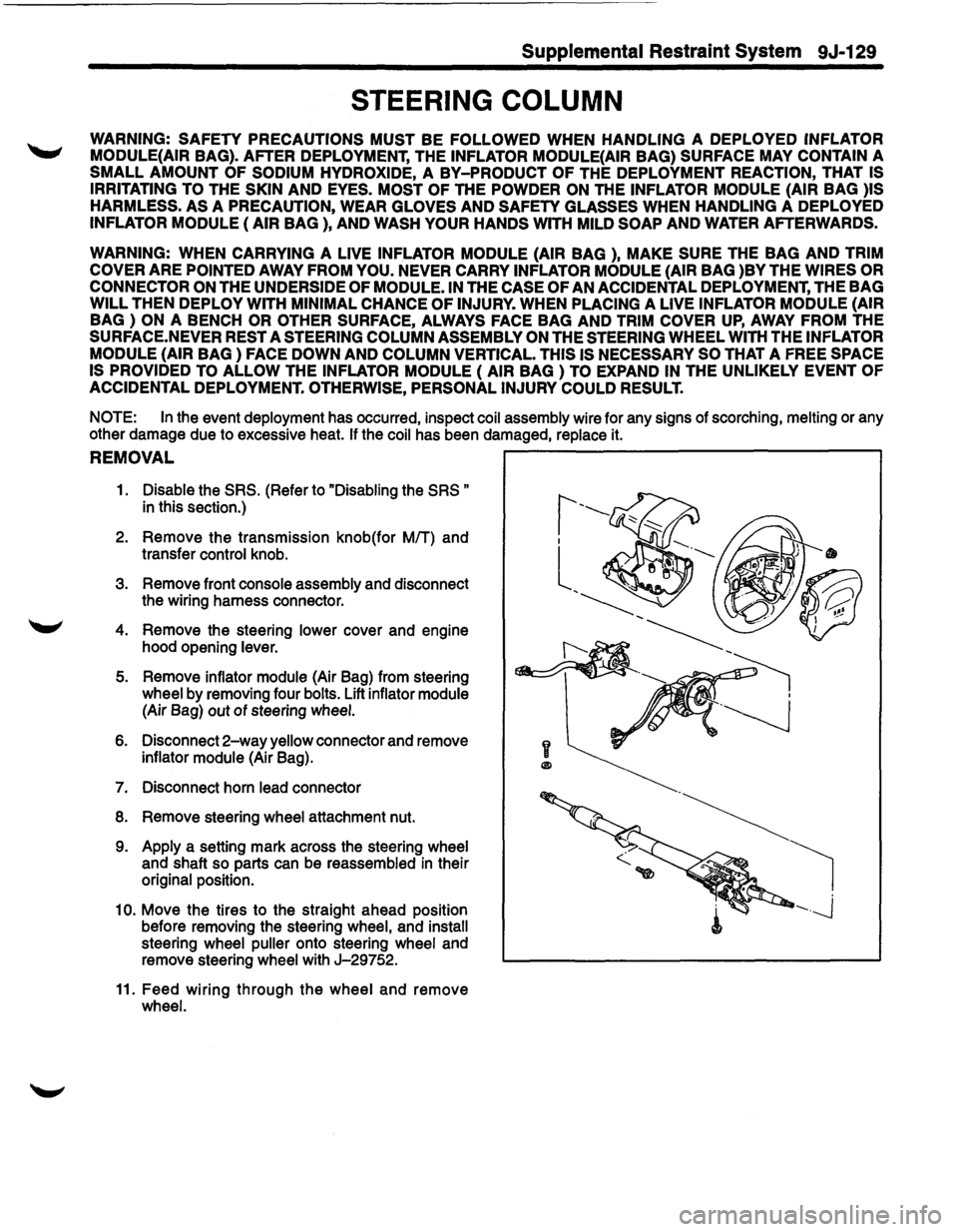
REMOVAL ~--------------------------~
1. Disable the SRS. (Refer to "Disabling the SRS "
in this section.)
2. Remove the transmission knob(for MIT) and
transfer
control knob.
3. Remove front console assembly and disconnect
the wiring harness connector.
4. Remove the steering lower cover and engine
hood opening
lever.
5. Remove inflator module (Air Bag) from steering
wheel by removing four bolts. Lift inflator module
(Air Bag) out of steering wheel.
6. Disconnect 2-way yellow connector and remove
inflator module (Air Bag).
7. Disconnect horn lead connector
8. Remove steering wheel attachment nut.
9. Apply a setting mark across the steering wheel
and shaft so parts can be reassembled in their
original position.
1
0. Move the tires to the straight ahead position
before removing the steering
wheel, and install
steering wheel puller onto steering wheel and
remove steering
wheel with J-29752.
11. Feed wiring through the wheel and remove
wheel.
y
®
Page 1755 of 1928
1 o. Connect the wiring harness connector located
base of steering column.
11. Turn the SRS coil clockwise to full, return about
3 turns and align the neutral mark.
CAUTION: WHEN TURNING THE SRS COIL
CLOCKWISE TO FULL, STOP TURNING IF
RESISTANCE IS FELT. FORCED FURTHER
TURNING MAY CAUSE DAMAGE TO THE CABLE IN
THE SRS COIL.
12. Install steering column cover.
CAUTION: WHEN INSTALLING THE STEERING
COLUMN COVER,
BE SURE TO WIRE {THROUGH
EACH HARNESS) AS ILLUSTRATED SO THAT THE
HARNESSES OF STARTER SWITCH,COMBINATION
SWITCH
AND SRS COIL MAY NOT CATCH WIRING.
13. Install the steering wheel and align the setting
marks.
14. Tighten the steering fixing nut to the specified
torque.
Torque: 34N·m(25 lb·ft.).
15. Connect horn lead connecor.
16. Connect inflator module to
2-way yellow wiring
harness connector.
17.
Install inflator module into steering wheel and
torque fasteners.
Torque: 8N·m(69 lb-in.)
18. Install the steering lower cover and engine hood
opening lever.
19.
Install front console assembly and connect the
wiring harness connector.
20.
Install the transmission knob(for M/T) and
transfer control knob.
21. Enable the
SRS (Refer to "Enabling the SRS" in
this section.).
Supplemental Restraint System 9J-131