engine oil ISUZU TROOPER 1995 Workshop Manual
[x] Cancel search | Manufacturer: ISUZU, Model Year: 1995, Model line: TROOPER, Model: ISUZU TROOPER 1995Pages: 1928
Page 906 of 1928
7 A-34 AUTOMATIC TRANSMISSION (4L30-E)
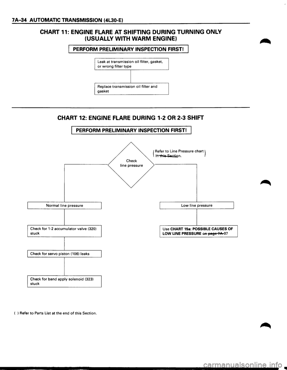
CHART 11: ENGINE FLARE AT SHIFTING DURING TURNING ONLY
(USUALLY WITH
WARM ENGINE)
PERFORM PRELIMINARY INSPECTION FIRST!
Leak at transmission oil filter, gasket, or wrong filter type
Replace transmission oil filter and
gasket
CHART 12: ENGINE FLARE DURING 1-2 OR 2-3 SHIFT
PERFORM PRELIMINARY INSPECTION FIRST!
Normal line pressure
Check for 1-2 accumulator valve (320) stuck
Check for servo piston (106) leaks
Check
for band apply solenoid (323) stuck
( ) Refer
to Parts List at the end of this Section.
Check
line pressure (
Refer
to Line
Pressure chart) t~n.
Low line pressure
Use CHART 15a:
POSSIBLE CAUSES OF
LOW LINE PRESSURE ~fM!~e 71/1t 37
..
Page 911 of 1928
AUTOMATIC TRANSMISSION (4L30-E) 7 A-39
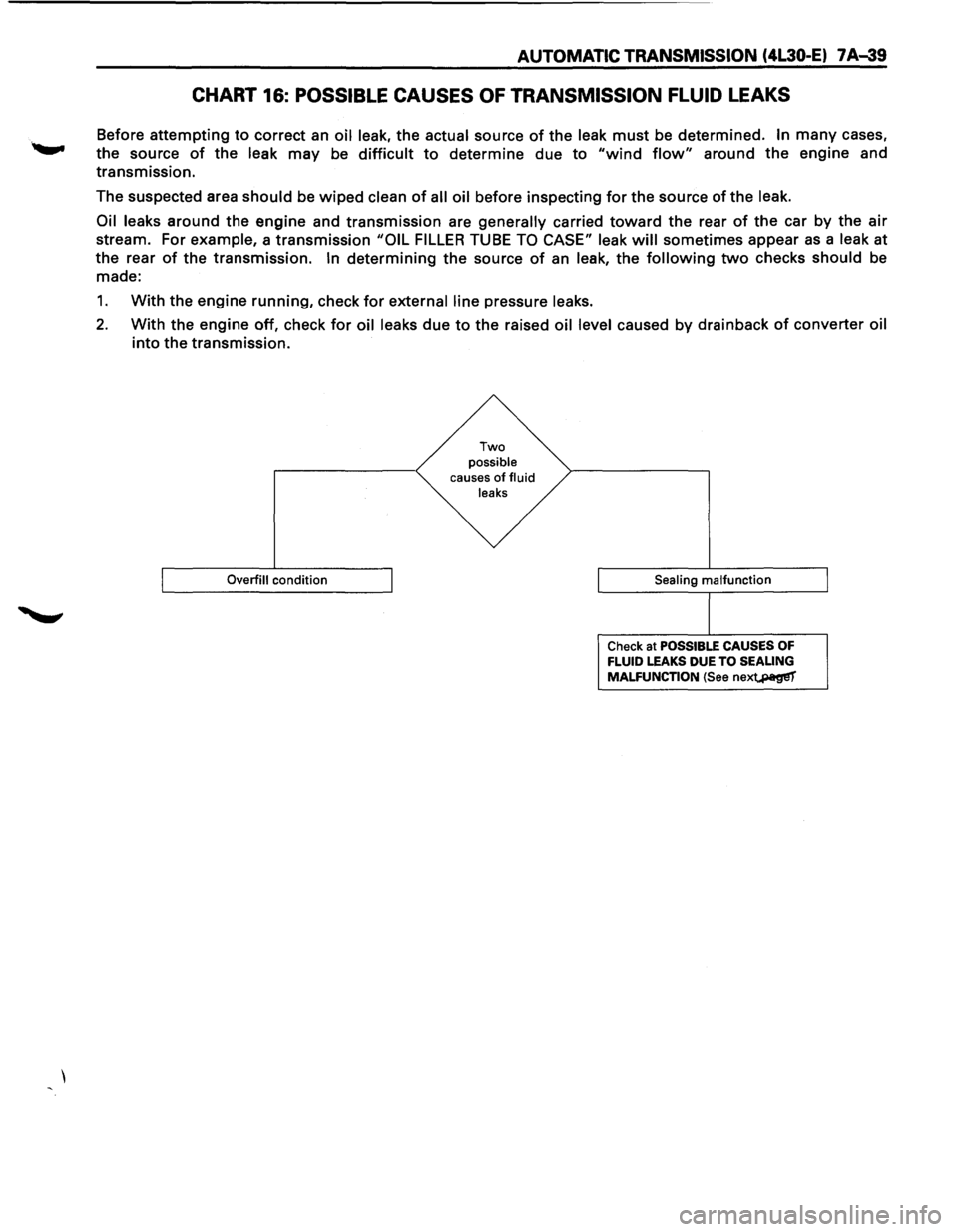
CHART 16: POSSIBLE CAUSES OF TRANSMISSION FLUID LEAKS
Before attempting to correct an oil leak, the actual source of the leak must be determined. In many cases,
the source
of the leak may be difficult to determine due to "wind flow" around the engine and
transmission.
The suspected area
should be wiped clean of all oil before inspecting for the source of the leak.
Oil leaks
around the engine and transmission are generally carried toward the rear of the car by the air
stream. For example, a transmission "OIL FILLER TUBE TO CASE" leak will sometimes appear as a leak at
the rear
of the transmission. In determining the source of an leak, the following two checks should be
made:
1. With the engine running, check for external line pressure leaks.
2. With the engine off, check for oil leaks due to the raised oil level caused by drainback of converter oil
into the transmission.
Overfill condition
Two possible causes of fluid
leaks
Sealing
malfunction
Check at POSSIBLE CAUSES OF FLUID LEAKS DUE TO SEALING
MALFUNCTION (See nex~
Page 913 of 1928
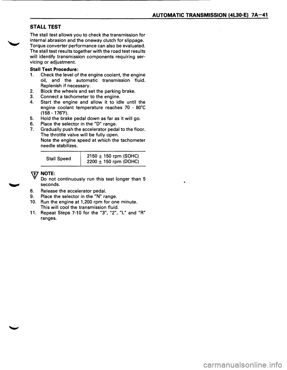
STALL TEST
The stall test allows you to check the transmission for
internal abrasion and the oneway clutch for slippage.
Torque converter performance can also be evaluated.
The
stall test results together with the road test results
will identify transmission components requiring ser
vicing or adjustment.
Stall Test Procedure:
1. Check the level of the engine coolant, the engine
oil, and the automatic transmission fluid.
Replenish
if necessary.
2. Block the wheels and set the parking brake.
3. Connect a tachometer to the engine.
4. Start the engine and allow it to idle until the
engine coolant temperature reaches
70 -8o·c
(158 -176.F).
5. Hold the brake pedal down as far as it will go.
6. Place the selector in the "D" range.
7. Gradually push the accelerator pedal to the floor.
The throttle valve
will be fully open.
Note the engine speed at which the tachometer
needle stabilizes.
Stall Speed
\fl NOTE:
2150 ± 150 rpm (SOHC)
2200 ± 150 rpm (DOHC)
VI Do not continuously run this test longer than 5
........, seconds.
8. Release the accelerator pedal.
9. Place the selector in the "N" range.
10. Run the engine at 1,200 rpm for one minute.
This
will cool the transmission fluid.
11. Repeat Steps 7-10 for the "3", "2", "L" and "R"
ranges.
AUTOMATIC TRANSMISSION (4L30-E) 7A-41
Page 914 of 1928
7 A-42 AUTOMATIC TRANSMISSION (4L30-E)
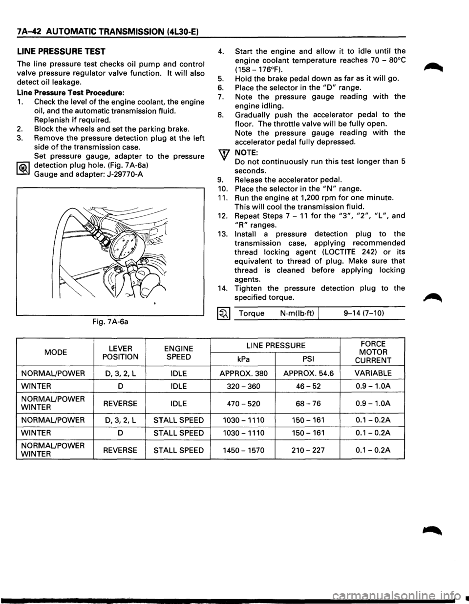
LINE PRESSURE TEST
The line pressure test checks oil pump and control
valve
pressure regulator valve function. It will also
detect oil leakage.
Line Pressure Test Procedure:
1. Check the level of the engine coolant, the engine
oil, and the automatic transmission fluid.
Replenish
if required.
2. Block the wheels and set the parking brake.
3. Remove the pressure detection plug at the left
side of the transmission case.
Set pressure gauge, adapter
to the pressure
l"iC\1 detection plug hole. (Fig. 7 A-6a)
~ Gauge and adapter: J-29770-A
Fig. 7A-6a
LEVER ENGINE
MODE
POSITION
SPEED
NORMAL/POWER D,3,2, L IDLE
WINTER D IDLE
NORMAL/POWER REVERSE IDLE WINTER
NORMAL/POWER
D,3,2,L STALL SPEED
WINTER D STALL SPEED
NORMAL/POWER REVERSE STALL SPEED WINTER
4.
5.
6.
7.
8.
9.
10.
11.
Start the engine and allow it to idle until the
engine
coolant temperature reaches 70 -80°C
(158-176°F).
Hold
the brake pedal down as far as it will go.
Place the selector in the "D" range.
Note the pressure gauge reading
with the
engine
idling.
Gradually
push the accelerator pedal to the
floor. The throttle valve will be fully open.
Note the pressure gauge reading
with the
accelerator
pedal fully depressed.
NOTE:
Do not continuously run this test longer than 5
seconds.
Release the accelerator pedal.
Place
the selector in the "N" range.
Run the engine at
1,200 rpm for one minute.
This
will cool the transmission fluid.
12. Repeat Steps 7-11 for the "3", "2", "L", and
"R" ranges.
13.
Install a pressure detection plug to the
transmission case,
applying recommended
thread
locking agent (LOCTITE 242) or its
equivalent to thread
of plug. Make sure that
thread is cleaned before applying locking
agents.
14. Tighten the pressure detection plug to the
specified torque.
~~~ Torque N·mOb·ft) / 9-14 (7-10)
LINE
PRESSURE FORCE
MOTOR kPa PSI CURRENT
APPROX. 380 APPROX. 54.6 VARIABLE
320-360 46-52 0.9 -1.0A
470-520 68-76 0.9 -1.0A
1030-1110 150-161 0.1-0.2A
1030-1110 150-161 0.1-0.2A
1450-1570 210-227 0.1-0.2A
•
Page 940 of 1928
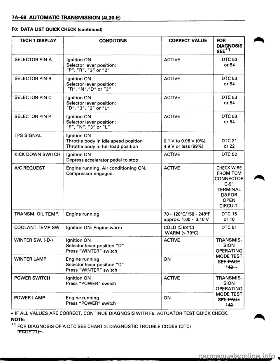
7A-68 AUTOMATIC TRANSMISSION (4l30-E)
FO: DATA LIST QUICK CHECK (continued)
TECH 1 DISPLAY
CONDITONS CORRECT VALUE FOR
DIAGNOSIS
SEE*1
SELECTOR PIN A Ignition ON ACTIVE DTC 53
Selector lever position: or 54
"P11, "R'', "311 or "211
SELECTOR PIN B Ignition ON ACTIVE DTC53
Selector lever position: or 54
"R11
, "N","D'' or "3''
SELECTOR PIN C Ignition ON ACTIVE DTC 53
Selector lever position: or 54
"D'', "311
, "211 or "L''
SELECTOR PIN P Ignition ON ACTIVE DTC 53
Selector lever position: or 54
"P11
, "N11, "311 or "Lu
TPS SIGNAL Ignition ON
Throttle body in idle speed position 0.1 V to 0.96 V (0%) DTC 21
Throttle body in full load position 4.9
V or less (99%) or 22
KICK DOWN SWITCH Ignition ON ACTIVE DTC 52
Depress accelerator pedal to stop
A!C REQUEST Engine running. Air conditioning ON. ACTIVE CHECK WIRE
Compressor
engaged. FROM TCM
CONNECTOR
C-91
TERMINAL
DB FOR
OPEN
CIRCUIT.
TRANSM. OIL
TEMP.
Engine running 70 -120°C/158 -248°F DTC 15
approx. 1.00 -3.10 V or16
COOLANT TEMP SW.
Ignition ON: Engine warm COLD (~ 63°C) DTC 51
WARM (> 70°C)
WINTER SW.
(-D-) Ignition ON ACTIVE TRANS
MIS-
Selector
lever position "D" SION
Press "WINTER" switch OPERATING
WINTER
LAMP Engine running ON MODE
TEST Sff-flAG£ Selector lever position "D" -,~ Press "WINTER" switch
POWER SWITCH Ignition ON ACTIVE TRANSMIS-
Press "POWER" switch SION
OPERATING
POWER LAMP Engine running ON MODE TEST
3!'Ef'AGE Press "POWER" switch l~·
• IF ALL VALUES ARE CORRECT, CONTINUE DIAGNOSIS WITH F5: ACTUATOR TEST QUICK CHECK.
NOTE:
*1
FOR DIAGNOSIS OF A DTC SEE CHART 2: DIAGNOSTIC TROUBLE CODES (DTC)
(PAGE Itt-
IIIII
Page 943 of 1928
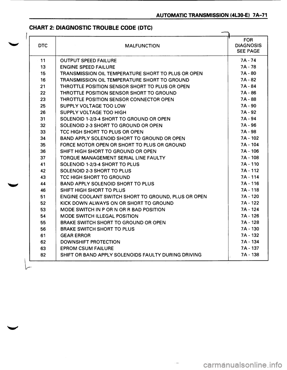
AUTOMATIC TRANSMISSION (4L30-E) 7 A-71
CHART 2: DIAGNOSTIC TROUBLE CODE (OTC)
I v
' FOR
DTC MALFUNCTION DIAGNOSIS
SEE PAGE
11 OUTPUT
SPEED FAILURE 7A -74
13 ENGINE SPEED FAILURE 7A -78
15 TRANSMISSION OIL TEMPERATURE SHORT TO PLUS OR OPEN 7A-80
16 TRANSMISSION OIL TEMPERATURE SHORT TO GROUND 7A-82
21 THROTTLE POSITION SENSOR SHORT TO PLUS OR OPEN 7A-84
22 THROTTLE POSITION SENSOR SHORT TO GROUND 7A-86
23 THROTTLE
POSITION SENSOR CONNECTOR OPEN 7A-88
25
SUPPLY VOLTAGE TOO LOW 7A-90
26 SUPPLY VOLTAGE TOO HIGH 7A-92
31 SOLENOID 1-2/3-4 SHORT TO GROUND OR OPEN 7A-94
32
SOLENOID 2-3 SHORT TO GROUND OR OPEN 7A-96
33 TCC
HIGH SHORT TO PLUS OR OPEN 7A-98
34
BAND APPLY SOLENOID SHORT TO GROUND OR OPEN 7A-102
35 FORCE MOTOR OPEN OR SHORT TO PLUS OR GROUND 7A-104
36 SHIFT HIGH SHORT TO GROUND OR OPEN 7A-106
37 TORQUE MANAGEMENT SERIAL LINE FAULTY 7A-108
41 SOLENOID 1-2/3-4 SHORT TO PLUS 7A-110
42 SOLENOID 2-3 SHORT TO PLUS 7A-112
43 TCC HIGH SHORT TO GROUND 7A-114
44
BAND APPLY SOLENOID SHORT TO PLUS 7A-116
46 SHIFT HIGH SHORT TO PLUS 7A-118
51 ENGINE COOLANT SWITCH SHORT TO GROUND, PLUS OR OPEN 7A-120
52 KICK DOWN ALWAYS ON OR SHORT TO GROUND 7A-122
53 MODE SWITCH IN P OR N OR R BAD POSITION 7A-124
54
MODE SWITCH ILLEGAL POSITION 7A-126
55 BRAKE
SWITCH SHORT TO GROUND OR OPEN 7A-128
56 BRAKE
SWITCH
SHORT TO PLUS 7A-130
61 GEAR ERROR 7A-132
62 DOWNSHIFT PROTECTION 7A-134
63
EPROM CSUM FAILURE 7A-137
82 SHIFT OR BAND APPLY SOLENOIDS FAULTY DURING DRIVING 7A-138
Page 945 of 1928
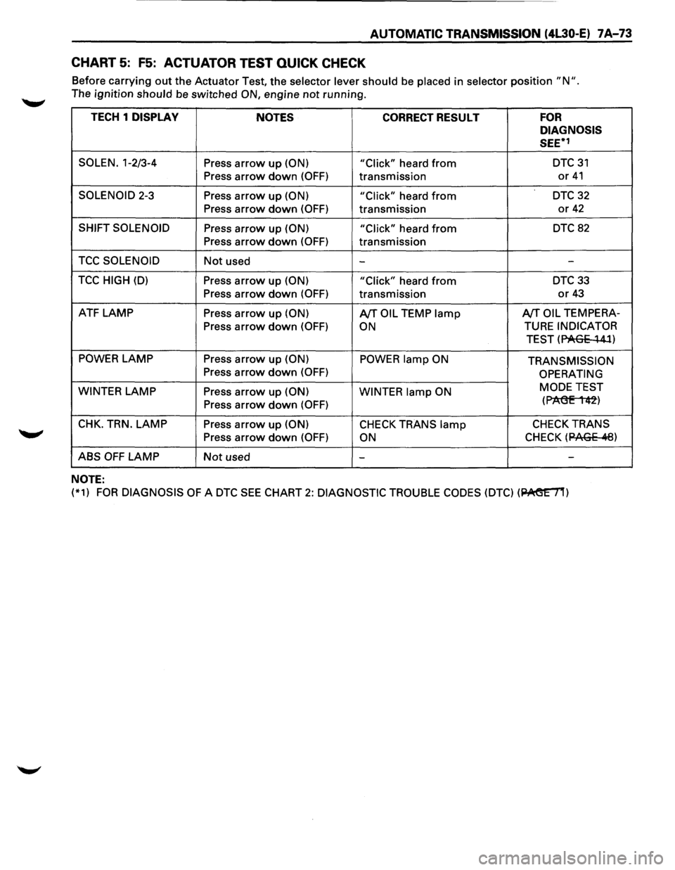
AUTOMATIC TRANSMISSION (4L30-E) 7A-73
CHART 5: F5: ACTUATOR TEST QUICK CHECK
Before carrying out the Actuator Test, the selector lever should be placed in selector position "N ".
The ignition should be switched ON, engine not running.
TECH 1 DISPLAY
NOTES CORRECT RESULT FOR
DIAGNOSIS
SEE*1
SOLEN. 1-2/3-4 Press arrow up (ON)
"Click" heard from DTC31
Press
arrow down (OFF) transmission or 41
SOLENOID 2-3 Press arrow up (ON) "Click" heard from DTC 32
Press arrow down (OFF) transmission or 42
SHIFT SOLENOID Press arrow up (ON)
"Click" heard from DTC 82
Press arrow down (OFF) transmission
TCC SOLENOID Not used --
TCC HIGH (D) Press arrow up (ON)
"Click" heard from DTC33
Press
arrow down (OFF) transmission or 43
ATF LAMP Press arrow up (ON) A/TOIL TEMP lamp A/TOIL TEMPERA-
Press
arrow down (OFF) ON TURE INDICATOR
TEST (PAGE
~ 41)
POWER LAMP
Press arrow up (ON) POWER lamp ON TRANSMISSION Press arrow down (OFF) OPERATING
WINTER
LAMP Press arrow up (ON)
WINTER lamp ON MODE
TEST
Press arrow down (OFF) (P1'\(3E 1 42)
CHK. TRN. LAMP Press arrow up (ON) CHECK TRANS lamp CHECK TRANS
Press arrow down (OFF) ON CHECK (12AGE .11:8)
ABS OFF LAMP Not used - -
NOTE:
(*1) FOR DIAGNOSIS OF A DTC SEE CHART 2: DIAGNOSTIC
TROUBLE CODES (DTC) (~)
Page 953 of 1928
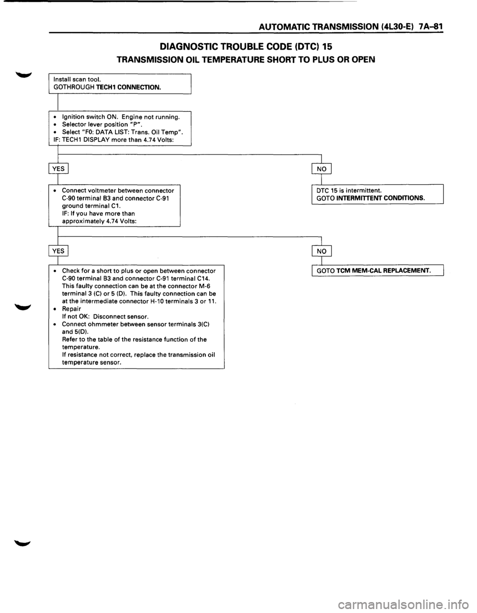
AUTOMATIC TRANSMISSION (4L30-E) 7 A-81
DIAGNOSTIC TROUBLE CODE (DTC) 15
TRANSMISSION OIL TEMPERATURE SHORT TO PLUS OR OPEN
Install scan tool.
GOTHROUGH
TECH1 CONNECTION.
• Ignition switch ON. Engine not running. • Selector lever position "P". • Select "FO: DATA LIST: Trans. Oil Temp". IF: TECH1 DISPLAY more than 4.74 Volts:
•
Connect voltmeter between connector C-90 terminal 83 and connector C-91 ground terminal C1.
IF: If you have more than approximately 4.74 Volts:
• Check
for a short to plus or open between connector C-90 terminal 83 and connector C-91 terminal C14. This faulty connection can be at the connector M-6 terminal 3 (C) or 5 (D). This faulty connection can be
at the intermediate connector
H-1 0 terminals 3 or 11. • Repair If not OK: Disconnect sensor.
• Connect ohmmeter between sensor terminals 3(C) and 5(D).
Refer
to the table of the resistance function of the
temperature.
If resistance not correct, replace the transmission oil temperature sensor.
DTC 15 is intermittent. GOTO INTERMITTENT CONDITIONS.
GOTO TCM MEM-CAL REPLACEMENT.
Page 955 of 1928
AUTOMATIC TRANSMISSION (4L30-E) 7 A-83
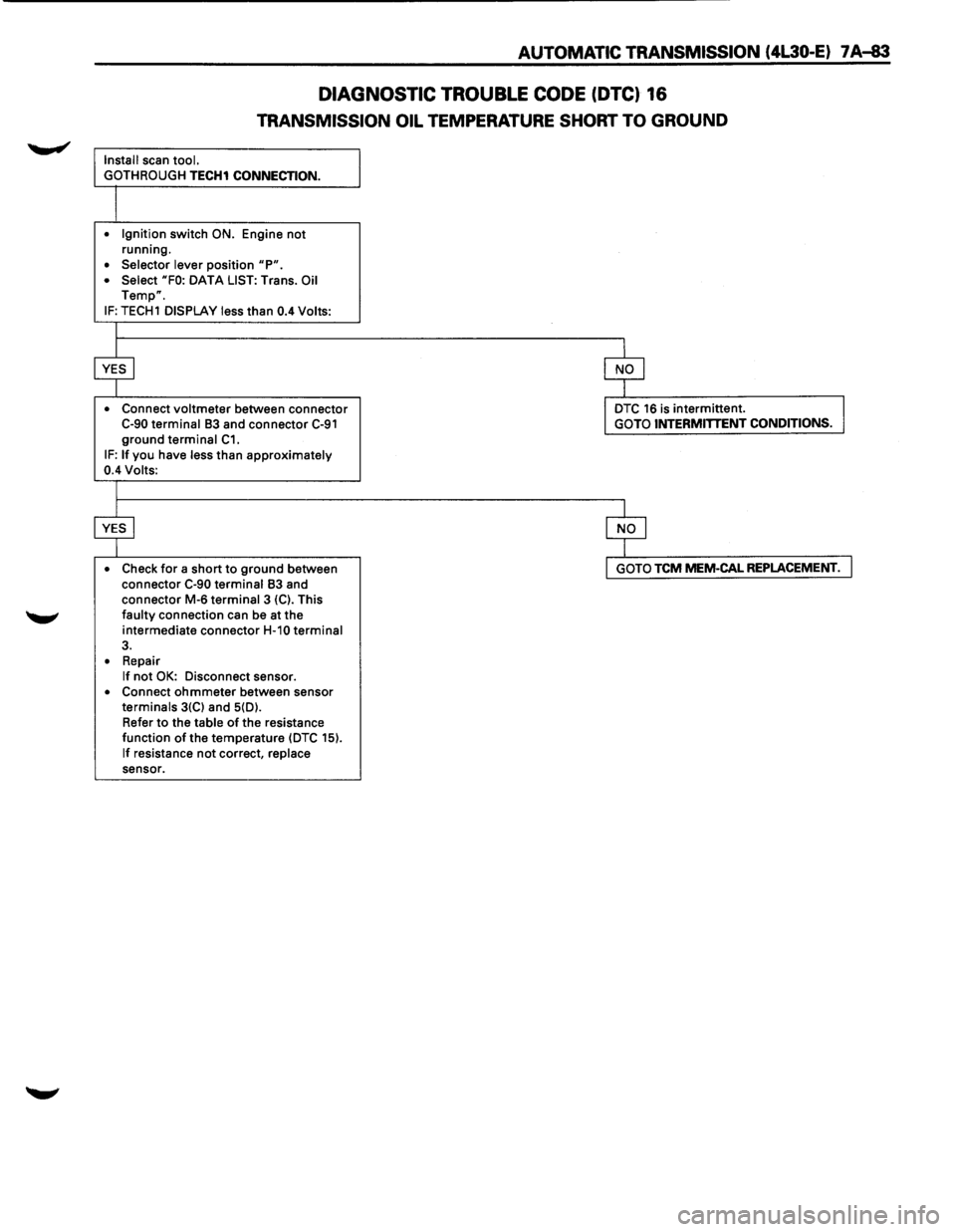
DIAGNOSTIC TROUBLE CODE (DTC) 16
TRANSMISSION OIL TEMPERATURE SHORT TO GROUND
Install scan tool.
GOTH ROUGH
TECH1 CONNECTION.
• Ignition switch ON. Engine not running.
• Selector lever position "P". • Select "FO: DATA LIST: Trans. Oil Temp".
IF: TECH1 DISPLAY less than 0.4 Volts:
• Connect
voltmeter between connector C-90 terminal 83 and connector C-91 ground terminal C1. IF: If you have less than approximately 0.4 Volts:
• Check
for a short to ground between
connector C-90 terminal 83 and
connector M-6 terminal 3 {C). This faulty connection can be at the
intermediate connector
H-10 terminal 3.
• Repair If not OK: Disconnect sensor. • Connect ohmmeter between sensor terminals 3{C) and 5{D).
Refer
to the table of the resistance
function of the temperature {DTC 15).
If resistance not correct, replace sensor.
DTC 16 is intermittent. GOTO INTERMITTENT CONDITIONS.
GOTO TCM MEM-CAL REPLACEMENT.
Page 962 of 1928
7 A-90 AUTOMATIC TRANSMISSION (4L30-E)
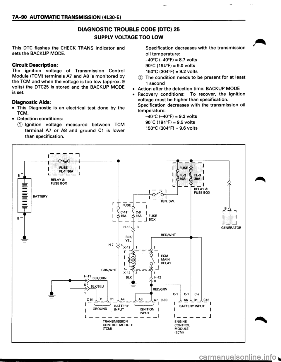
DIAGNOSTIC TROUBLE CODE (DTC) 25
SUPPLY VOLTAGE TOO LOW
This DTC flashes the CHECK TRANS indicator and
sets the BACKUP
MODE.
Specification decreases with the transmission
oil temperature:
Circuit Description:
-40°C (-40°F) = S.7 volts
90°C (194°F) = 9.0 volts
150°C (304°F) = 9.2 volts The ignition voltage of Transmission Control
Module (TCM) terminals A7 and AS is monitored by
the TCM and when the voltage is too low (approx. 9
volts) the DTC25 is stored and the BACKUP MODE
is set.
@ The condition needs to be present for at least
1 second
• Action after the detection time: BACKUP MODE
Diagnostic Aids:
• This Diagnostic is an electrical test done by the
TCM.
• Recovery conditions: To recover, the ignition
voltage must be higher than specification.
Specification decreases
with the transmission oil
temperature:
-40°C (-40°F) = 9.2 volts
90°C (194°F) = 9.5 volts
150°C (304°F) = 9.6 volts
• Detection conditions:
CD Ignition voltage measured between TCM
terminal A7 or AS and ground C1 is lower
than specification .
. · fU I
I '
f:L;~soA L., ____ J
RELAY & FUSE BOX
1--, {)-:,.--____..J BATTERY
l
T
L __ I
r
I C-14 C-8 I I 15A 15A FUSE -__ + _ j BOX
H-13t 3
H-7 'x~.~~'---7 r ]_-
GRN/WHT
BATTERY I GROUND INPUT IGNITION I INPUT I
L-----------TRANSMISSION
CONTROL MODULE
(TCM) IGN.SW.
RED/WHT
C-1 C-1 C-2
A6 B1 C16
r -;ATTERV INPUT-l
I
I l _____ j
ENGINE
CONTROL MODULE
(ECM)
I I
I-_j GENERATOR