ignition ISUZU TROOPER 1995 Workshop Manual
[x] Cancel search | Manufacturer: ISUZU, Model Year: 1995, Model line: TROOPER, Model: ISUZU TROOPER 1995Pages: 1928
Page 758 of 1928
6E2~62 DRIVEABILITY AND EMISSIONS
DIAGNOSTIC TROUBLE CODE (DTC) 148
ENGINE COOLANT TEMPERATURE (ECT) SENSOR CIRCUIT
(LOW TEMPERATURE INDICATED)
Circuit Description:
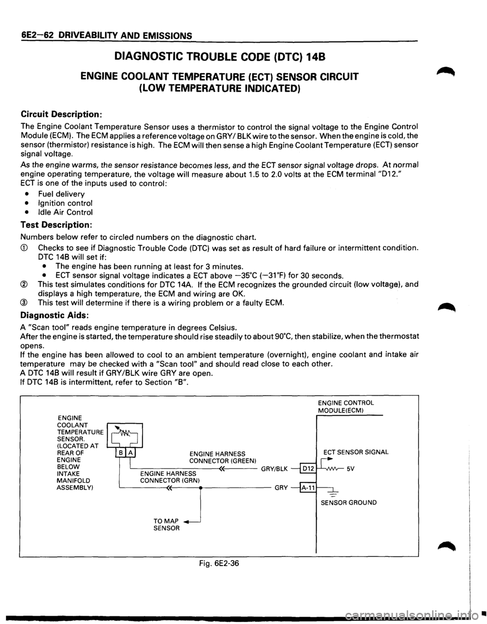
The Engine Coolant Temperature Sensor uses a thermistor to control the signal voltage to the Engine Control
Module (ECM). The ECM applies a reference voltage on GRY I 8LK wire to the sensor. When the engine is cold, the
sensor (thermistor) resistance
is high. The ECM will then sense a high Engine Coolant Temperature (ECT) sensor
signal
voltage.
As the engine warms, the sensor resistance becomes less, and the ECT sensor signal voltage drops. At normal
engine operating temperature, the voltage will measure about 1.5 to 2.0 volts at the ECM terminal "012."
ECT is one of the inputs used to control:
• Fuel delivery
• Ignition control
• Idle
Air Control
Test Description:
Numbers below refer to circled numbers on the diagnostic chart.
CD Checks to see if Diagnostic Trouble Code (DTC) was set as result of hard failure or intermittent condition.
DTC 148 will set if:
• The engine has been running at least for 3 minutes.
• ECT sensor signal voltage indicates a ECT above -35°C (-31 OF) for 30 seconds.
® This test simulates conditions for DTC 14A. If the ECM recognizes the grounded circuit (low voltage), and
displays a high temperature, the ECM and wiring are OK.
@ This test will determine if there is a wiring problem or a faulty ECM.
Diagnostic Aids:
A "Scan tool" reads engine temperature in degrees Celsius.
After the engine is started, the temperature should rise steadily to about 90°C, then stabilize, when the thermostat
opens.
If the engine has been allowed to cool to an ambient temperature (overnight), engine coolant and intake air
temperature may be checked
with a "Scan tool" and should read close to each other.
A
DTC 148 will result if GRY/8LK wire GRY are open.
If DTC 148 is intermittent, refer to Section "8".
ENGINE
COOLANT
TEMPERATURE SENSOR.
(LOCATED AT REAR OF ENGINE
BELOW
INTAKE
MANIFOLD
ASSEMBLY) ENGINE
HARNESS
CONNECTOR (GREEN) c__---------<~'----GRY/BLK ENGINE HARNESS
CONNECTOR (GRN)
~---T-0--<'M<(--A-P_J ___________ GRY
SENSOR
Fig. 6E2-36
ENGINE CONTROL MODULE(ECM)
ECT
SENSOR SIGNAL
SENSOR GROUND
•
Page 771 of 1928
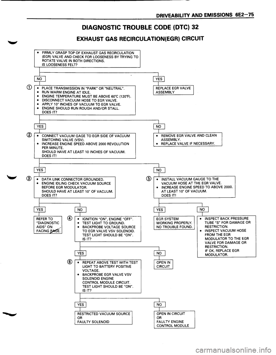
DIAGNOSTIC TROUBLE CODE (DTC) 32
EXHAUST GAS RECIRCULATION(EGR) CIRCUIT
• FIRMLY GRASP TOP OF EXHAUST GAS RECIRCULATION (EGR} VALVE AND CHECK FOR LOOSENESS BY TRYING TO
ROTATE VALVE IN BOTH DIRECTIONS.
IS LOOSENESS FELT?
l
$
-[$J
• PLACE TRANSMISSION IN "PARK" OR "NEUTRAL". REPLACE EGR VALVE I • RUN WARM ENGINE AT IDLE. ASSEMBLY
• ENGINE TEMPERATURE MUST BE ABOVE 60'C (120'F). • DISCONNECT VACUUM HOSE TO EGR VALVE. • APPLY 10"1NCHES OF VACUUM TO EGR VALVE. • ENGINE SHOULD RUN ROUGH AND/OR STALL.
DOES IT?
I
$ $
•
CONNECT VACUUM GAGE TO EGR SIDE OF VACUUM • REMOVE EGR VALVE AND CLEAN SWITCHING VALVE (VSV). ASSEMBLY.
• INCREASE ENGINE SPEED ABOVE 2000 REVOLUTION • REPLACE
VALVE IF NECESSARY. PER MINUTE.
SHOULD HAVE AT LEAST 10 INCHES OF VACUUM. DOES IT!
I
$ $
• DATA LINK CONNECTOR GROUNDED . @ • INSTALL VACUUM GAUGE TO THE
• ENGINE IDLING CHECK VACUUM SOURCE VACUUM HOSE AT THE EGR VALVE. BEFORE EGR MODULATOR. • INCREASE ENGINE SPEED TO ABOVE 2000 . SHOULD HAVE AT LEAST 10" OF VACUUM. AT LEAST 10" OF VACUUM. DOES IT? DOES IT!
I
I
$ $ $ ~
REFER TO @ • IGNITION "ON", ENGINE "OFF". EGR SYSTEM • INSPECT BACK PRESSURE
"DIAGNOSTIC • TEST LIGHT TO GROUND. WORKING PROPERLY. TUBE "S" FOR DAMAGE OR AIDS" ON
.
• BACKPROBE VOLTAGE SOURCE NO
TROUBLE FOUND. RESTRICTION. FACING'¢{ TO EGR VALVE VSV
SOLENOID. •
INSPECT VACUUM HOSE
TEST LIGHT SHOULD BE "ON". FROM THE EGR
IS IT? MODULATOR TO THE EGR
I VALVE FOR DAMAGE OR
$ $
RESTRICTION. IF OK, REPLACE EGR MODULATOR.
@ • REPEAT ABOVE TEST WITH TEST
OPEN IN I LIGHT TO BATTERY POSITIVE CIRCUIT VOLTAGE.
• BACKPROBE EGR VALVE VSV
SOLENOID ENGINE
CONTROL MODULE CIRCUIT.
TEST LIGHT SHOULD
BE "ON". IS IT?
I
$ $
RESTRICTED VACUUM SOURCE OPEN
IN CIRCUIT OR OR FAULTY SOLENOID FAULTY ENGINE
CONTROL MODULE
Page 772 of 1928
6E2-76 DRIVEABILITY AND EMISSIONS
DIAGNOSTIC TROUBLE CODE (DTC) 33A
MANIFOLD ABSOLUTE PRESSURE (MAP) SENSOR CIRCUIT
(SIGNAL
VOLTAGE HIGH-LOW VACUUM)
Circuit Description:
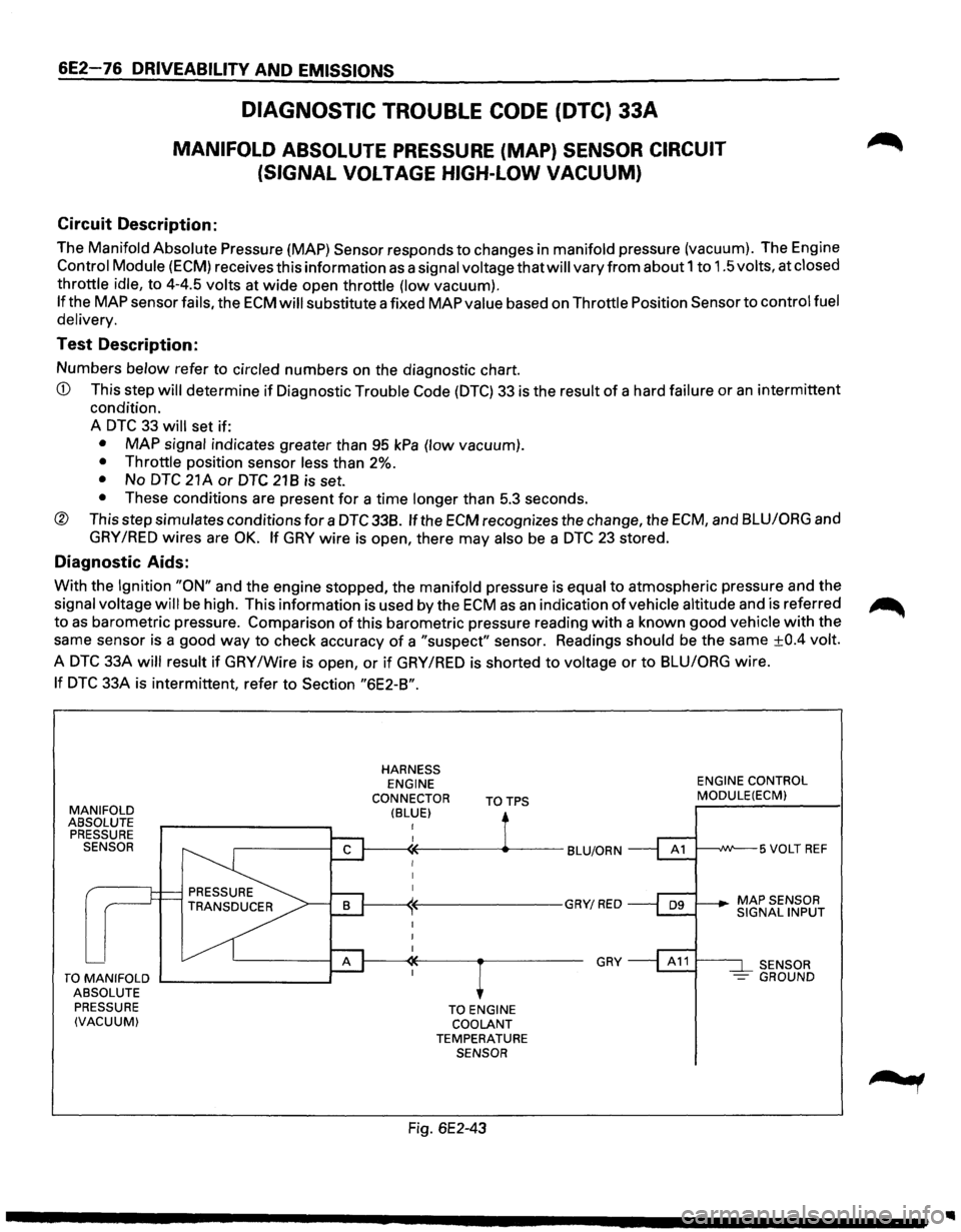
The Manifold Absolute Pressure {MAP) Sensor responds to changes in manifold pressure (vacuum). The Engine
Control Module (ECM) receives this information as a signal voltage that will vary from about 1 to 1.5 volts, at closed
throttle idle, to 4-4.5 volts at
wide open throttle (low vacuum).
If the MAP sensor fails, the ECM will substitute a fixed MAP value based on Throttle Position Sensor to control fuel
delivery.
Test Description:
Numbers below refer to circled numbers on the diagnostic chart.
CD This step will determine if Diagnostic Trouble Code (DTC) 33 is the result of a hard failure or an intermittent
condition.
A
DTC 33 will set if:
• MAP signal indicates greater than 95 kPa (low vacuum).
• Throttle position sensor less than 2%.
• No DTC 21 A or DTC 21 B is set.
• These conditions are present for a time longer than 5.3 seconds.
® This step simulates conditions for a DTC 338. If the ECM recognizes the change, the ECM, and BLU/ORG and
GRY /RED wires are OK. If GRY wire is open, there may also be a DTC 23 stored.
Diagnostic Aids:
With the Ignition "ON" and the engine stopped, the manifold pressure is equal to atmospheric pressure and the
signal voltage
will be high. This information is used by the ECM as an indication of vehicle altitude and is referred ~
to as barometric pressure. Comparison of this barometric pressure reading with a known good vehicle with the
same sensor is a good
way to check accuracy of a "suspect" sensor. Readings should be the same ±0.4 volt.
A
DTC 33A will result if GRY /Wire is open, or if GRY /RED is shorted to voltage or to BLU/ORG wire.
If DTC 33A is intermittent, refer to Section "6E2-B".
MANIFOLD ABSOLUTE
PRESSURE
SENSOR
TO MANIFOLD ....__ _______ __,
ABSOLUTE
PRESSURE
(VACUUM)
HARNESS ENGINE
CONNECTOR
(BLUE) TOTPS
TO ENGINE
COOLANT
TEMPERATURE SENSOR
Fig. 6E2-43
GRY
ENGINE CONTROL MODULE(ECM)
t---~W--5 VOLT REF
SENSOR
- GROUND
Page 773 of 1928
CD
®
DRIVEABILITY AND EMISSIONS 6E2-77
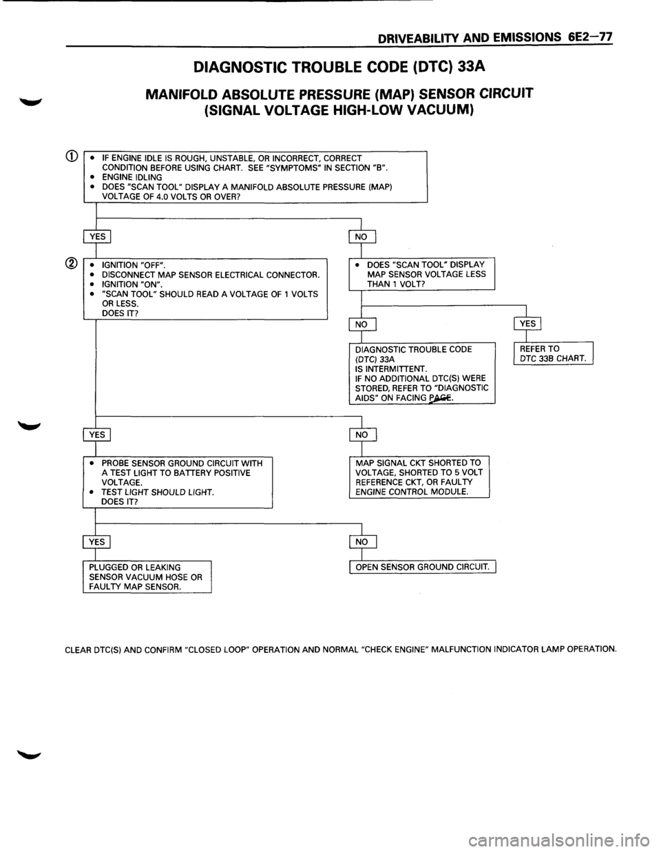
DIAGNOSTIC TROUBLE CODE (DTC) 33A
MANIFOLD ABSOLUTE PRESSURE (MAP) SENSOR CIRCUIT
(SIGNAL
VOLTAGE HIGH-LOW VACUUM)
• IF ENGINE IDLE IS ROUGH, UNSTABLE, OR INCORRECT, CORRECT CONDITION BEFORE USING CHART. SEE "SYMPTOMS" IN SECTION "B". • ENGINE IDLING
• DOES "SCAN TOOL" DISPLAY A MANIFOLD ABSOLUTE PRESSURE (MAP)
VOLTAGE OF 4.0 VOLTS OR OVER?
~ $
• IGNITION "OFF". •
DOES "SCAN TOOL" DISPLAY
• DISCONNECT MAP SENSOR ELECTRICAL CONNECTOR. MAP SENSOR VOLTAGE LESS
• IGNITION "ON". THAN 1 VOLT? • "SCAN TOOL" SHOULD READ A VOLTAGE OF 1 VOLTS I OR LESS.
DOES IT?
$ $
DIAGNOSTIC TROUBLE
CODE l REFER TO J (DTC) 33A DTC
33B CHART. IS INTERMITTENT. IF NO ADDITIONAL DTC(S) WERE STORED, REFER TO "DIAGNOSTIC AIDS" ON FACING ~-
~ $
• PROBE SENSOR GROUND CIRCUIT WITH MAP SIGNAL CKT SHORTED TO A TEST LIGHT TO BATTERY POSITIVE VOLTAGE,
SHORTED TO 5 VOLT
VOLTAGE. REFERENCE CKT, OR FAULTY • TEST LIGHT SHOULD LIGHT. ENGINE CONTROL MODULE.
DOES IT?
$ $
PLUGGED OR LEAKING OPEN SENSOR GROUND CIRCUIT.
SENSOR VACUUM HOSE OR FAULTY MAP SENSOR.
CLEAR DTC(S) AND CONFIRM "CLOSED LOOP" OPERATION AND NORMAL "CHECK ENGINE" MALFUNCTION INDICATOR LAMP OPERATION.
Page 774 of 1928
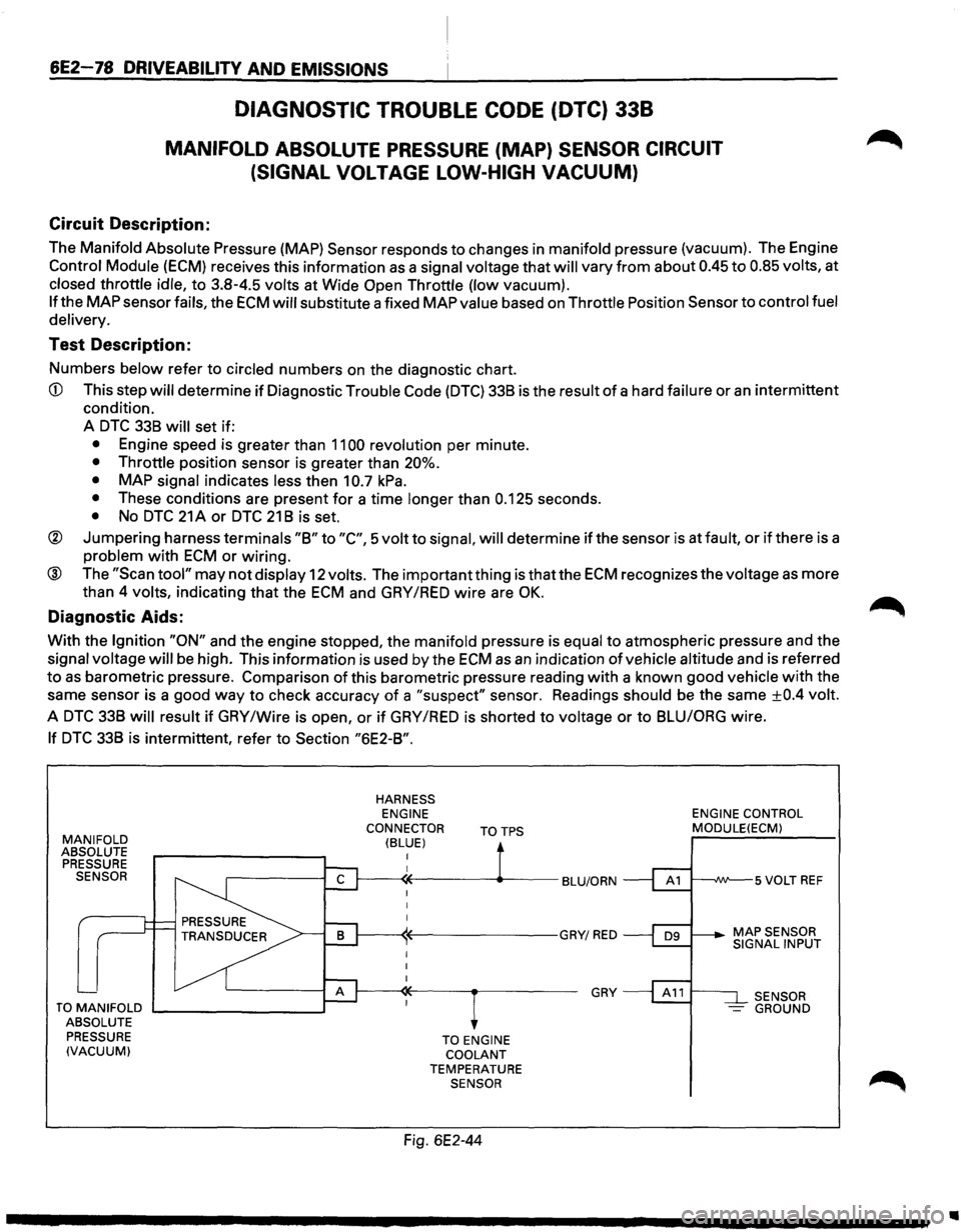
6E2-78 DRIVEABILITV AND EMISSIONS
DIAGNOSTIC TROUBLE CODE (DTC) 338
MANIFOLD ABSOLUTE PRESSURE (MAP) SENSOR CIRCUIT
(SIGNAL
VOLTAGE LOW-HIGH VACUUM)
Circuit Description:
The Manifold Absolute Pressure (MAP) Sensor responds to changes in manifold pressure (vacuum). The Engine
Control Module (ECM) receives this information as a signal voltage that will vary from about 0.45 to 0.85 volts, at
closed throttle idle, to 3.8-4.5 volts at Wide Open Throttle (low vacuum).
If the MAP sensor fails, the ECM will substitute a fixed MAP value based on Throttle Position Sensor to control fuel
delivery.
Test Description:
Numbers below refer to circled numbers on the diagnostic chart.
CD This step will determine if Diagnostic Trouble Code (DTC) 338 is the result of a hard failure or an intermittent
condition.
A
DTC 338 will set if:
• Engine speed is greater than 1100 revolution per minute.
• Throttle position sensor is greater than 20%.
•
MAP signal indicates less then 10.7 kPa.
• These conditions are present for a time longer than 0.125 seconds.
• No DTC 21 A or DTC 21 8 is set.
® Jumpering harness terminals "8" to "C", 5 volt to signal, will determine if the sensor is at fault, or if there is a
problem with ECM or wiring.
® The "Scan tool" may not display 12 volts. The important thing is that the ECM recognizes the voltage as more
than 4
volts, indicating that the ECM and GAY /RED wire are OK.
Diagnostic Aids:
With the Ignition "ON" and the engine stopped, the manifold pressure is equal to atmospheric pressure and the
signal voltage will be high. This information is used by the ECM as an indication of vehicle altitude and is referred
to as barometric pressure. Comparison of this barometric pressure reading with a known good vehicle with the
same sensor is a good
way to check accuracy of a "suspect" sensor. Readings should be the same ±0.4 volt.
A DTC 338 will result if GAY /Wire is open, or if GAY /RED is shorted to voltage or to 8LUIORG wire.
If DTC 338 is intermittent, refer to Section "6E2-8".
MANIFOLD ABSOLUTE
PRESSURE SENSOR
TO MANIFOLD .._ _______ --.~
ABSOLUTE
PRESSURE
(VACUUM)
HARNESS ENGINE
CONNECTOR
(BLUE) TOTPS
TO ENGINE COOLANT TEMPERATURE SENSOR
Fig. 6E2-44
GRY
ENGINE CONTROL MODULE(ECM)
SENSOR -GROUND
..
Page 775 of 1928
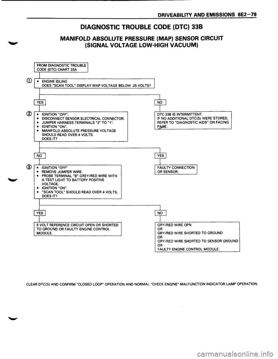
DRIVEABILITY AND EMISSIONS 6E2-79
DIAGNOSTIC TROUBLE CODE (DTC) 338
MANIFOLD ABSOLUTE PRESSURE (MAP) SENSOR CIRCUIT
(SIGNAL VOLTAGE LOW-HIGH
VACUUM)
CD • ENGINE IDLING
DOES "SCAN TOOL" DISPLAY MAP VOLTAGE BELOW .25 VOLTS?
@ • IGNITION "OFF".
• DISCONNECT SENSOR ELECTRICAL CONNECTOR.
•
JUMPER HARNESS TERMINALS "2" TO "1". • IGNITION "ON". • MANIFOLD ABSOLUTE PRESSURE VOLTAGE SHOULD READ OVER 4 VOLTS.
DOES IT?
@ • IGNITION "OFF"
• REMOVE JUMPER WIRE.
• PROBE TERMINAL "B" GREY /RED WIRE WITH 'W' A TEST LIGHT TO BATTERY POSITIVE VOLTAGE. • IGNITION "ON". • "SCAN TOOL" SHOULD READ OVER 4 VOLTS.
DOES IT?
5 VOLT REFERENCE CIRCUIT OPEN OR SHORTED
TO GROUND OR FAUL TV ENGINE CONTROL MODULE.
DTC 33B IS INTERMITTENT. IF NO ADDITIONAL DTC{S) WERE STORED, REFER TO "DIAGNOSTIC AIDS" ON FACING p
GRY/RED WIRE OPN OR GRY/RED WIRE SHORTED TO GROUND OR GRY/RED WIRE SHORTED TO SENSOR GROUND OR FAUL TV ENGINE CONTROL MODULE.
CLEAR DTC{S) AND CONFIRM "CLOSED LOOP" OPERATION AND NORMAL "CHECK ENGINE" MALFUNCTION INDICATOR LAMP OPERATION.
Page 776 of 1928
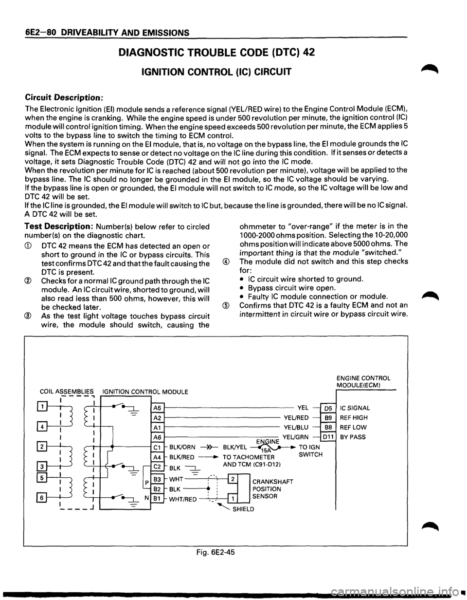
6E2-80 DRIVEABILITV AND EMISSIONS
Circuit Description:
DIAGNOSTIC TROUBLE CODE (DTC) 42
IGNITION CONTROL (IC) CIRCUIT
The Electronic Ignition (EI) module sends a reference signal (YEL/RED wire) to the Engine Control Module (ECM),
when the engine is cranking. While the engine speed is under 500 revolution per minute, the ignition control (IC)
module will control ignition timing. When the engine speed exceeds 500 revolution per minute, the ECM applies 5
volts to the bypass line to switch the timing to ECM control.
When the system is running on the El module, that is, no voltage on the bypass line, the El module grounds the IC
signal. The ECM expects to sense or detect no voltage on the IC line during this condition. If it senses or detects a
voltage,
it sets Diagnostic Trouble Code (DTC) 42 and will not go into the IC mode.
When the revolution per minute
for IC is reached (about 500 revolution per minute), voltage will be applied to the
bypass
line. The IC should no longer be grounded in the El module, so the IC voltage should be varying.
If the bypass line is open or grounded, the El module will not switch to IC mode, so the IC voltage will be low and
DTC 42 will be set.
If the IC line is grounded, the El module will switch to IC but, because the line is grounded, there will be no IC signal.
A DTC 42 will be set.
Test Description: Number(s) below refer to circled
number(s) on the diagnostic chart.
CD DTC 42 means the ECM has detected an open or
short to ground in the IC or bypass circuits. This
test confirms
DTC 42 and that the fault causing the
DTC is present.
® Checks for a normaiiC ground path through the IC
module. An IC circuit wire, shorted to ground, will
also
read less than 500 ohms, however, this will
be checked later.
® As the test light voltage touches bypass circuit
wire, the
module should switch, causing the ohmmeter
to "over-range" if the
meter is in the
1000-2000 ohms position. Selecting the 10-20,000
ohms position will indicate above 5000 ohms. The
important thing is that the module
"switched."
® The module did not switch and this step checks
for:
• IC circuit wire shorted to ground.
• Bypass circuit wire open.
• Faulty IC module connection or module.
@ Confirms that DTC 42 is a faulty ECM and not an
intermittent in circuit wire or bypass circuit wire.
ENGINE CONTROL
MODULE(ECM)
~--------------------------VEL
~----------------------YE~RED
~----------------------YE~BLU
IC SIGNAL
REF HIGH
REF LOW
BY PASS YE~GRN D11
BLK/ORN ----)}-BLK!YEL ~ TO IGN
BLK/RED -TO TACHOMETER SWITCH
BLK ~ AND TCM (C91-D12)
WHT :' '1 CRANKSHAFT
BLK -----..~ ! POSITION
WHT/RED ',_; 1 SENSOR
"SHIELD
Fig. 6E2-45
..
Page 777 of 1928
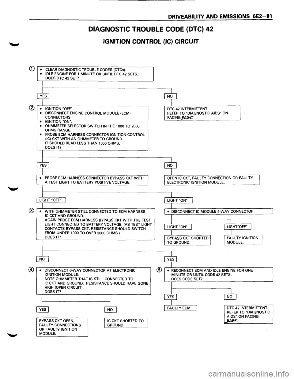
CD
®
DRIVEABILITY AND EMISSIONS 6E2-81
DIAGNOSTIC TROUBLE CODE (DTC) 42
IGNITION CONTROL (IC) CIRCUIT
• CLEAR DIAGNOSTIC TROUBLE CODES (DTCs). • IDLE ENGINE FOR 1 MINUTE OR UNTIL DTC 42 SETS.
DOES DTC 42 SET?
~ $
• IGNITION "OFF" DTC 42 INTERMITTENT.
• DISCONNECT ENGINE CONTROL MODULE (ECM) REFER TO "DIAGNOSTIC AIDS" ON
CONNECTORS. FACING~ • IGNITION "ON".
• OHMMETER SELECTOR SWITCH IN THE 1 000 TO 2000
OHMS RANGE. • PROBE ECM HARNESS CONNECTOR IGNITION CONTROL (IC) CKT WITH AN OHMMETER TO GROUND. IT SHOULD READ LESS THAN 1000 OHMS.
DOES IT?
~ $
• PROBE ECM HARNESS CONNECTOR BYPASS CKT WITH OPEN IC CKT, FAULTY CONNECTION OR FAULTY
I A TEST LIGHT TO BATTERY POSITIVE VOLTAGE. ELECTRONIC IGNITION MODULE.
L LIGHT "OFF" I LIGHT "ON" I
I
• WITH OHMMETER STILL CONNECTED TO ECM HARNESS • DISCONNECT IC MODULE 4-wAY CONNECTOR. IC CKT AND GROUND. L AGAIN PROBE ECM HARNESS BYPASS CKT WITH THE TEST
I I
LIGHT CONNECTED TO BATTERY VOLTAGE. (AS TEST LIGHT
LIGHT "ON" j LIGHT"OFF" I CONTACTS BYPASS CKT, RESISTANCE SHOULD SWITCH
FROM UNDER 1000 TO OVER 2000 OHMS.) I l DOES IT? BYPASS CKT SHORTED I FAULTY IGNITION I
TO GROUND. MODULE.
~ $
•
DISCONNECT 6-WAY CONNECTOR AT ELECTRONIC ® • RECONNECT ECM AND IDLE ENGINE FOR ONE
IGNITION MODULE. MINUTE OR UNTIL CODE 42 SETS.
NOTE OHMMETER THAT IS STILL CONNECTED TO
DOES CODE SET? IC CKT AND GROUND. RESISTANCE SHOULD HAVE GONE I HIGH (OPEN CIRCUIT).
DOES IT?
$ $
$ $
FAULTY ECM I DTC 42 INTERMITTENT. REFER TO "DIAGNOSTIC
AIDS" ON FACING
BYPASS
CKT OPEN, IIC CKT SHORTED TO ~ FAULTY CONNECTIONS GROUND. OR FAULTY IGNITION MODULE.
Page 778 of 1928
6E2-82 DRIVEABILITY AND EMISSIONS
Circuit Description:
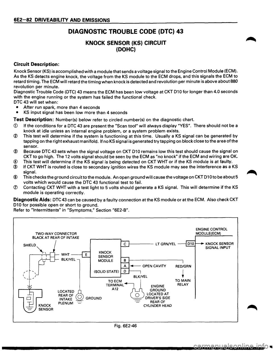
DIAGNOSTIC TROUBLE CODE (DTC) 43
KNOCK SENSOR (KS) CIRCUIT
(DOHC)
Knock Sensor (KS) is accomplished with a module that sends a voltage signal to the Engine Control Module (ECM).
As the KS detects engine knock, the voltage from the KS module to the ECM drops, and this signals the ECM to
retard timing. The ECM will retard the timing when knock is detected and revolution per minute is above about 880
revolution
per minute.
Diagnostic
Trouble Code (DTC) 43 means the ECM has been low voltage at CKT 010 for longer than 4.0 seconds
with the engine running or the system has
failed the functional check.
DTC 43 will set when:
• After run spark, more than 4 seconds
• KS input signal has been low more than 4 seconds
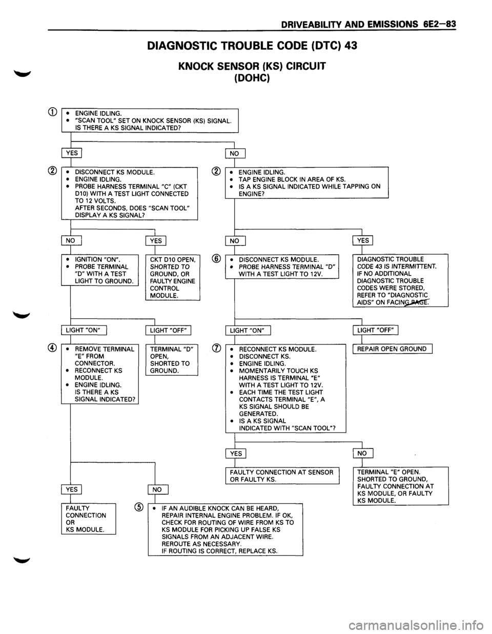
Test Description: Number(s) below refer to circled number(s) on the diagnostic chart.
CD If the conditions for a DTC 43 are present the "Scan tool" will always display "YES". There should not be a
knock at
idle unless an internal engine problem, or a system problem exists.
® This test will determine if the system is functioning at this time. Usually a KS signal can be generated by
tapping on the right exhaust
manifold. If no KS signal is generated try tapping on block close to the area of the
sensor.
® Because DTC 43 sets when the signal voltage on CKT 010 remains low this test should cause the signal on
CKT to go high. The 12 volts signal should be seen by the ECM as "no knock" if the ECM and wiring are OK.
@ This test will determine if the KS signal is being detected on CKT WHT or if the KS module is at faulty.
@ If CKT WHT is routed is close to secondary ignition wires the KS module may see the interference as a KS
signal. ~
® This checks the ground circuitto the module. An open ground will cause the voltage on CKT 010 to be about 5
volts which would cause the DTC 43 functional test to fail.
(J) Contacting CKT WHT with a test light to 5 volts should generate a KS signal. This will determine if the KS
module is operating correctly.
Diagnostic Aids: DTC43 can be caused by a faulty connection atthe KS module or atthe ECM. Also check CKT
010 for possible open or short to ground.
Refer
to "lntermittents" in "Symptoms," Section "6E2-B".
TWO-WAY CONNECTOR
BLACK AT REAR OF INTAKE
-' / I I
WHT
BLK!YEL
LOCATED REAR OF 0 INTAKE PLENUM
1-----L T GRN/YEL
KNOCK
SENSOR
MODULE
BLK/YEL
GROUND
TOECM ~ TERMINAL ENGINE A12 GROUND
0 LOCATEDAT _ DRIVER'S SIDE REAR OF CYLINDER HEAD
Fig. 6E2-46
RED/GRN
+ TO MAIN RELAY
ENGINE CONTROL MODULE(ECM)
KNOCK SENSOR SIGNAL INPUT
Page 779 of 1928
CD
DRIVEABILITV AND EMISSIONS 6E2-83
• ENGINE IDLING.
DIAGNOSTIC TROUBLE CODE (DTC) 43
KNOCK SENSOR (KS) CIRCUIT
(DOHC)
• "SCAN TOOL" SET ON KNOCK SENSOR (KS} SIGNAL. IS THERE A KS SIGNAL INDICATED?
~ $
• DISCONNECT KS MODULE. ® • ENGINE IDLING.
• ENGINE IDLING. • TAP ENGINE BLOCK IN AREA OF KS. • PROBE HARNESS TERMINAL "C" (CKT • IS A KS SIGNAL INDICATED WHILE TAPPING ON
D10} WITH A TEST LIGHT CONNECTED
ENGINE?
TO 12 VOLTS. AFTER SECONDS, DOES "SCAN TOOL"
DISPLAY A KS SIGNAL?
$ ~ ~ ~ • IGNITION "ON". CKT D10 OPEN, @ • DISCONNECT KS MODULE. DIAGNOSTIC
TROUBLE
• PROBE TERMINAL SHORTED TO • PROBE HARNESS TERMINAL "D" CODE 43 IS INTERMITTENT. "D" WITH A TEST
GROUND, OR WITH A TEST LIGHT TO 12V. IF NO ADDITIONAL
LIGHT TO GROUND. FAULTY ENGINE DIAGNOSTIC TROUBLE
CONTROL CODES WERE STORED,
MODULE.
REFER TO "DIA~= AIDS" ON FAGIN .
I I
LIGHT "ON" I LIGHT "OFF" I LIGHT "ON" j LIGHT "OFF" I
I
I
• REMOVE TERMINAL TERMINAL "D" (J) • RECONNECT KS MODULE. REPAIR
OPEN GROUND I "E" FROM
OPEN, • DISCONNECT KS . CONNECTOR.
SHORTED TO • ENGINE IDLING.
• RECONNECT KS GROUND. • MOMENTARILY TOUCH KS MODULE.
HARNESS IS TERMINAL "E" • ENGINE IDLING. WITH A TEST LIGHT TO 12V. IS THERE A KS • EACH TIME THE TEST LIGHT
SIGNAL INDICATED?
CONTACTS TERMINAL "E", A KS SIGNAL SHOULD BE GENERATED. • IS A KS SIGNAL
INDICATED WITH "SCAN TOOL"?
~ $
~
FAULTY CONNECTION AT SENSOR TERMINAL "E" OPEN. OR FAULTY KS. SHORTED
TO GROUND,
~
FAULTY CONNECTION AT KS MODULE, OR FAULTY KS MODULE. FAULTY @ • IF AN AUDIBLE KNOCK CAN BE HEARD, CONNECTION
REPAIR INTERNAL ENGINE PROBLEM. IF OK, OR CHECK FOR ROUTING OF WIRE FROM KS TO KS MODULE. KS MODULE FOR PICKING UP FALSE KS SIGNALS FROM AN ADJACENT WIRE.
REROUTE AS NECESSARY. IF ROUTING IS CORRECT, REPLACE KS.