wiring ISUZU TROOPER 1995 Workshop Manual
[x] Cancel search | Manufacturer: ISUZU, Model Year: 1995, Model line: TROOPER, Model: ISUZU TROOPER 1995Pages: 1928
Page 1637 of 1928
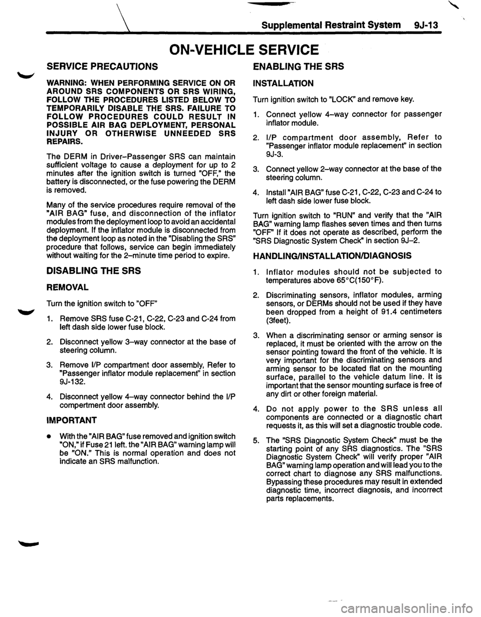
Supplemental Restraint System 9J-13
ON-VEHICLE SERVICE
SERVICE PRECAUTIONS
WARNING: WHEN PERFORMING SERVICE ON OR
AROUND SRS COMPONENTS OR SRS WIRING,
FOLLOW
THE PROCEDURES LISTED BELOW TO
TEMPORARILY DISABLE THE SRS. FAILURE TO
FOLLOW PROCEDURES COULD RESULT IN
POSSIBLE AIR
BAG DEPLOYMENT, PERSONAL
INJURY OR OTHERWISE
UNNEEDED SRS
REPAIRS.
The DERM in Driver-Passenger SRS can maintain
sufficient voltage to cause a deployment for up to 2
minutes after the ignition switch is turned
"OFF," the
battery is disconnected, or the fuse powering the DERM
is removed.
Many of the service procedures require removal of the
"AIR BAG" fuse, and disconnection of the inflator
modules from the deployment loop to avoid an accidental
deployment.
If the inflator module is disconnected from
the deployment loop as noted in the "Disabling the
SRS"
procedure that follows, service can begin immediately
without waiting for the 2-minute time period to expire.
DISABLING THE SRS
REMOVAL
Turn the ignition switch to "OFF"
1. Remove SRS fuse C-21, C-22, C-23 and C-24 from
left dash side lower fuse block.
2. Disconnect yellow 3-way connector at the base of
steering column.
3. Remove 1/P compartment door assembly, Refer to
"Passenger inflator module replacement" in section
9J-132.
4. Disconnect yellow 4-way connector behind the 1/P
compartment door assembly.
IMPORTANT
• With the "AIR BAG" fuse removed and ignition switch
"ON," if Fuse 21 left. the "AIR BAG" warning lamp will
be "ON." This is normal operation and does not
indicate an
SRS malfunction.
ENABLING THE SRS
INSTALLATION
Turn ignition switch to "LOCK" and remove key.
1. Connect yellow 4-way connector for passenger
inflator module.
2. 1/P compartment door assembly, Refer to
"Passenger inflator module replacemenf' in section
9J-3.
3. Connect yellow 2-way connector at the base of the
steering column.
4. Install "AIR BAG" fuse C-21, C-22, C-23 and C-24 to
left dash side lower fuse block.
Turn ignition switch to
"RUN" and verify that the "AIR
BAG"
warning lamp flashes seven times and then turns
"OFP' If it does not operate as described, perform the
"SRS Diagnostic System Check" in section 9J-2.
HANDLING/INSTALLATION/DIAGNOSIS
1. Inflator modules should not be subjected to
temperatures above
65°C{150°F).
2. Discriminating sensors, inflator modules, arming
sensors, or DERMs should not be used if they have
been dropped from a height
of 91.4 centimeters
{3feet).
3. When a discriminating sensor or arming sensor is
replaced, it must be oriented with the arrow on the
sensor pointing toward the front of the vehicle.
It is
very important for the discriminating sensors and
arming sensor to be located flat on the mounting
surface, parallel to the vehicle datum line.
It is
important that the sensor mounting surface is free of
any dirt or other foreign material.
4. Do not apply power to the SRS unless all
components are connected or a diagnostic chart
requests it, as this
will set a diagnostic trouble code.
5. The "SRS Diagnostic System Check" must be the
starting point of any
SRS diagnostics. The "SRS
Diagnostic System Check" will verify proper "AIR
BAG"
warning lamp operation and will lead you to the
correct chart to diagnose any
SRS malfunctions.
Bypassing these procedures may result
in extended
diagnostic time, incorrect diagnosis, and incorrect
parts replacements.
Page 1649 of 1928
, Supplem~l Restraint System
SPECIAL TOOLS
WARNING: TO AVOID DEPLOYMENT WHEN
'-' TROUBLESHOOTING THE SRS, DO NOT USE
ELECTRICAL TEST EQUIPMENT SUCH AS A
BATTERY-POWERED OR AC-POWERED
VOLTMETER, OHMMETER, ETC., OR ANY TYPE OF
ELECTRICAL EQUIPMENT OTHER THAN THAT
SPECIFIED IN THIS MANUAL. DO NOT USE A
NON-POWERED PROBE TYPE TESTER.
INSTRUCTIONS IN THIS MANUAL MUST BE
FOLLOWED CAREFULLY, OTHERWISE PERSONAL
INJURY
MAY RESULT.
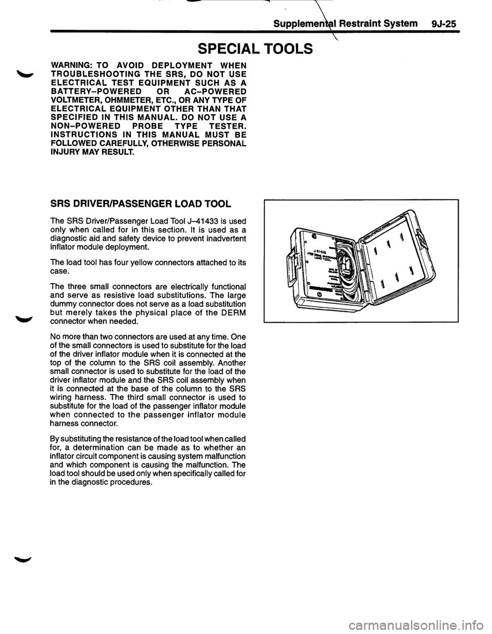
SRS DRIVER/PASSENGER LOAD TOOL
The SRS Driver/Passenger Load Tool J-41433 is used
only when called for in this section. It is used as a
diagnostic aid and safety device to prevent inadvertent
inflator
module deployment.
The
load tool has four yellow connectors attached to its
case.
The three
small connectors are electrically functional
and serve as resistive
load substitutions. The large
dummy connector does not serve as a load substitution
but
merely takes the physical place of the DERM
connector when needed.
No more than two connectors are used at any time.
One
of the small connectors is used to substitute for the load
of the driver inflator module when it is connected at the
top of the
column to the SRS coil assembly. Another
small connector is used to substitute for the load of the
driver inflator
module and the SRS coil assembly when
it is connected at the base of the
column to the SRS
wiring harness. The third small connector is used to
substitute for the
load of the passenger inflator module
when connected to the passenger inflator module
harness connector.
By substituting the resistance of the
load tool when called
for, a determination can be made as to whether an
inflator circuit component is causing system malfunction
and which component is causing the malfunction. The
load tool should be used only when specifically called for
in the diagnostic procedures.
9J-25
Page 1654 of 1928
9J-30 Supplemental Restraint System (SRS)
HOW TO USE THIS SECTION
DIAGNOSTIC PROCEDURES
WARNING: TO AVOID DEPLOYMENT WHEN
TROUBLESHOOTING THE SRS, DO NOT USE
ELECTRICAL TEST EQUIPMENT SUCH AS A
BATTERY-POWERED OR AC-POWERED
VOLTMETER, OHMMETR,ETC. ,OR ANY TYPE OF
ELECTRICAL EQUIPMENT OTHER THAN THAT
SPECIFIED IN THIS MANUAL. DO NOT USE A
NON-POWERED PROBE TYPE TESTER.
INSTRUCTIONS IN THIS MANUAL MUST BE
FOLLOWED CAREFULLY, OTHERWISE PERSONAL
INJURY
MAY RESULT.
The diagnostic procedures used in this section are
designed to aid
in finding and repairing SRS problems.
Outlined below
are the steps to find and repair SRS
problems quickly
and effectively. Failure to carefully
follow these procedures may result in extended
diagnostic time, incorrect diagnosis and incorrect parts
replacement.
1. Perform the "SRS Diagnostic System Check". The
"SRS Diagnostic System Check" should always be
the starting point of any SRS diagnostics. The "SRS
Diagnostic System Check" checks for proper "AIR
BAG" indicator operation and checks for SRS trouble
codes using both "Flash Code" and "Scan Tool"
Methods.
2. Refer to the proper diagnostic chart as directed by
the
"SRS Diagnostic System Check". The "SRS
Diagnostic System Check" will lead you to the correct
chart to diagnose any
SRS problems. Bypassing
these procedures may
result in extended diagnostic
time, incorrect diagnosis and incorrect parts
replacement.
3. Repeat the "SRS Diagnostic System Check" after
any repair
or diagnostic procedures have been
performed.Performing the
"SRS Diagnostic System
Check" after all repair or diagnostic procedures will
assure that the repair has been made correctly and
that no other conditions exist.
DIAGNOSTIC CODES
The Diagnostic Energy Reserve Module (DERM)
maintains a history record of all diagnostic codes that
have been detected since the
SRS codes were last
cleared
during service.
1. Current Codes -Faults that are presently detected
this ignition
cycle. Active and Cycle codes are stored
in RAM (Random Access Memory).
2. History
Codes-All faults detected since the last time
the history
fault memory was cleared. History codes
are stored in EEPROM (Electrically Erasable
Programmable Read Only Memory )
HOW TO READ TROUBLE CODES
All codes (Active cycle and history) can be read (or
cleared) by using a Scan Tool (Portable Diagnostic Tool
[PDT)) or equivalent. If a PDT is not available, have the
vehicle serviced by a Saturn Dealer.
HOW TO CLEAR TROUBLE CODES
Trouble codes can only be cleared by using a Scan Tool.
If
a "Scan Tool" is not available, then inform the owner of
the stored codes and suggest that the codes are
cleared
upon the next visit to a ISUZU dealership.
SCAN TOOL DIAGNOSTICS
A Scan Tool can be used to read current and history
codes and to
clear all history codes after a repair is
complete. The scan tool must be updated to
communicate with the
SRS through a replaceable
cartridge or a manufacturer's update before it can be
used for
SRS diagnostics. To use the scan tool, connect
it to the ALDL connector and turn the ignition switch
"ON". Then follow the manufacturer's directions for
communication with the
SRS. The scan tool reads serial
data from the DERM "Serial Data" output (terminal A 11)
to the ALDL connector (terminal M) Via ISUZU
Convertible Connector (terminal 2).
BASIC KNOWLEDGE REQUIRED
Before using this section of the Service Manual, there is
some basic
knowledge which will be required. Without
this knowledge, you
will have trouble using the diagnostic
procedures
in this section. Use care to prevent harm or
unwanted
deployment. Read all cautions in the service
manual and on warning labels attached to SRS
components.
BASIC ELECTRICAL CIRCUITS
You should understand the basic theory of electricity
including series and parallel circuits, and understand the
voltage drops across series resistors. You should know
the meaning of
voltage (volts), current (amps), and
resistance (ohms). You should understand what
happens in a circuit with an open or a shorted wire. You
should be able to read and understand a wiring diagram.
"FLASH CODE" DIAGNOSTICS
"Flash Code" diagnostics are not implemented for SRS
diagnostic on TROOPER(UX)Vehicles.
Page 1660 of 1928
9J-36 Supplemental Restraint System
TABLE B
"AIR BAG" WARNING LAMP COMES "ON" STEADY
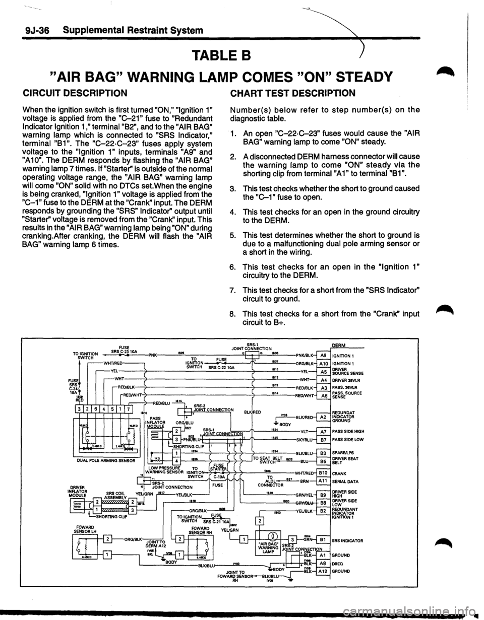
CIRCUIT DESCRIPTION
When the ignition switch is first turned "ON," "Ignition 1"
voltage is applied from the "C-21" fuse to "Redundant
Indicator Ignition 1 ,"terminal "B2", and to the "AIR BAG"
warning lamp which is connected to "SRS Indicator,"
terminal "B1". The "C-22·C-23" fuses apply system
voltage to the
"Ignition 1" inputs, terminals "A9" and
"A10". The DERM responds by flashing the "AIR BAG"
warning lamp 7 times. If "Starter" is outside of the normal
operating voltage range, the
"AIR BAG" warning lamp
will
come "ON" solid with no DTCs set. When the engine
is being cranked,
"Ignition 1" voltage is applied from the
"C-1" fuse to the DERM at the "Crank" input. The DERM
responds by grounding the
"SRS" Indicator" output until
"Starter" voltage is removed from the "Crank'' input. This
results in the
"AIR BAG" warning lamp being "ON" during
cranking.After cranking, the DERM
will flash the "AIR
BAG" warning lamp 6 times.
CHART TEST DESCRIPTION
Number(s) below refer to step number(s) on the
diagnostic table.
1. An open "C-22-C-23" fuses would cause the "AIR
BAG" warning lamp to come "ON" steady.
2. A disconnected DERM harness connector will cause
the warning
lamp to come "ON" steady via the
shorting clip from terminal "A1" to terminal "81".
3. This test checks whether the short to ground caused
the
"C-1" fuse to open.
4. This test checks for an open in the ground circuitry
to the DERM.
5. This test determines whether the short to ground is
due to a malfunctioning dual pole arming sensor or
a short
in the wiring.
6. This test checks for an open in the "Ignition 1"
circuitry to the DERM.
7. This test checks for a short from the "SRS Indicator''
circuit to ground.
8. This test checks for a short from the "Crank" input
circuit to 8+.
SRS-1 JOINT CONNECTION TO IGNITION FUSE SRS C·23 10A 1!015 '12 10 IGNITION I IGNITION 1 SWITCH
FUSE~ SRS C-24 10A .... R D
PASS.3eVLR PASS. SOURCE SENSE
PASS SlOE HIGH
PASS SlOE LOW
SERIAL DATA
SRS INDICATOR
..
Page 1666 of 1928
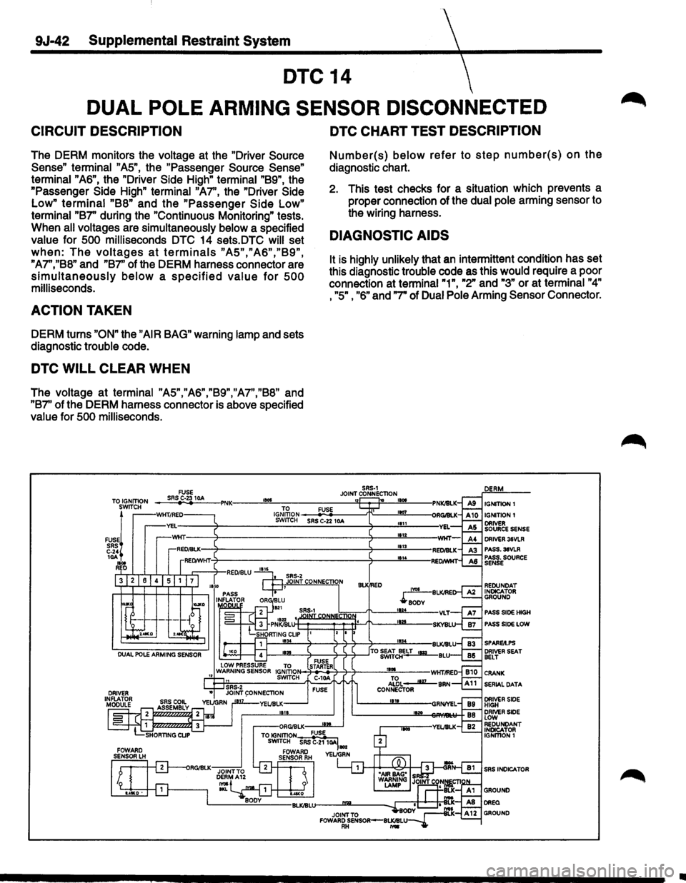
9J-42 Supplemental Restraint System
DTC 14
DUAL
POLE ARMING SENSOR DISCONNECTED
CIRCUIT DESCRIPTION
The DERM monitors the voltage at the "Driver Source
Sense" terminal
"AS", the "Passenger Source Sense"
terminal "AS",
the "Driver Side High" terminal "B9", the
"Passenger
Side High" terminal "A7'', the "Driver Side
Low" terminal
"88" and the "Passenger Side Low"
terminal "87" during the "Continuous Monitoring" tests.
When
all voltages are simultaneously below a specified
value for 500 milliseconds DTC 14 sets.DTC will set
when: The voltages at terminals "A5","A6","B9",
"A7","B8" and "B7'' of the DERM harness connector are
simultaneously below a specified value for 500
milliseconds.
ACTION TAKEN
DERM turns "ON" the "AIR BAG" warning lamp and sets
diagnostic
trouble code.
DTC WILL CLEAR WHEN
The voltage at terminal "A5","A6","B9","A7","B8" and
"87'' of the DERM harness connector is above specified
value for 500 milliseconds.
~~ 10A 1101 RD
DTC CHART TEST DESCRIPTION
Number(s) below refer to step number(s) on the
diagnostic chart.
2. This test checks for a situation which prevents a
proper connection of the
dual pole arming sensor to
the wiring harness.
DIAGNOSTIC AIDS
It is highly unlikely that an intermittent condition has set
this diagnostic
trouble code as this would require a poor
connection at
terminal"1", "2" and "3" or at terminal "4"
, "5" ,
"6" and "7" of Dual Pole Arming Sensor Connector.
IGNmDNt
PASS.38VLR PASS. SOURCE SENSE
PASS SIDE HIGH
PASS SIDE LOW
SERIAL DATA
SRS INDICATOR
Ill
Page 1668 of 1928
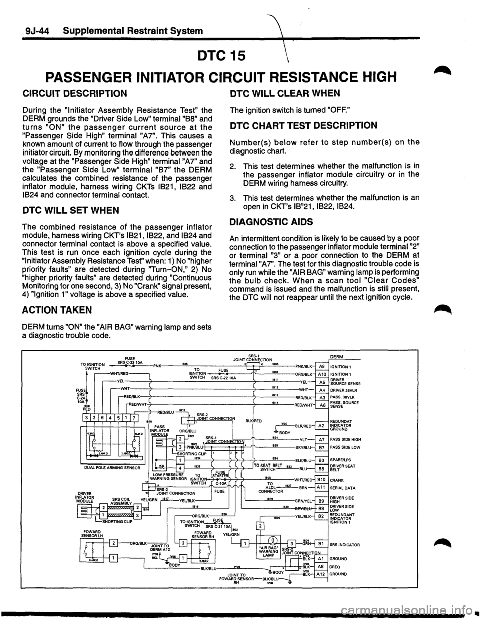
9J-44 Supplemental Restraint System
DTC 15
PASSENGER INITIATOR CIRCUIT RESISTANCE HIGH
CIRCUIT DESCRIPTION
During the "Initiator Assembly Resistance Test" the
DERM grounds the
"Driver Side Low" terminal "BB" and
turns "ON" the passenger current source at the
"Passenger Side High" terminal "A7". This causes a
known amount of current to
flow through the passenger
initiator circuit. By monitoring the difference between the
voltage at the "Passenger Side High" terminal "A7" and
the "Passenger
Side Low" terminal "B7" the DERM
calculates the combined resistance of the passenger
inflator module, harness wiring CKTs IB21, IB22 and
IB24 and connector terminal contact.
DTC WILL SET WHEN
The combined resistance of the passenger inflator
module,
harness wiring CKT's IB21, IB22, and IB24 and
connector
terminal contact is above a specified value.
This test is run once each ignition cycle during the
"Initiator Assembly Resistance Tesf' when: 1) No "higher
priority faults" are detected during "Turn-ON," 2) No
"higher priority faults" are detected during "Continuous
Monitoring for one second, 3) No "Crank" signal present,
4) "Ignition 1" voltage is above a specified value.
ACTION TAKEN
DERM turns "ON" the "AIR BAG" warning lamp and sets
a diagnostic
trouble code.
DTC WILL CLEAR WHEN
The ignition switch is turned "OFF."
DTC CHART TEST DESCRIPTION
Number(s) below refer to step number(s) on the
diagnostic chart.
2. This test determines whether the malfunction is in
the passenger inflator module circuitry or in the
DERM wiring harness circuitry.
3. This test determines whether the malfunction is an
open in CKT's IB"21, IB22, IB24.
DIAGNOSTIC AIDS
An intermittent condition is likely to be caused by a poor
connection to the passenger
inflator module terminal "2"
or terminal "3" or a poor connection to the DERM at
terminal "A7''. The test for this diagnostic trouble code is
only run while the "AIR BAG" warning lamp is performing
the
bulb check. When a scan tool "Clear Codes"
command is issued and the malfunction is still present,
the
DTC will not reappear until the next ignition cycle.
DRIVER 36VLR PASS. 36VLR PASS. SOURCE SENSE
REDUNDAT INDICATOR GROUND
PASS SIDE HIGH
PASS SIDE LOW
SERIAL DATA
SRS INDICATOR
Ill
Page 1670 of 1928
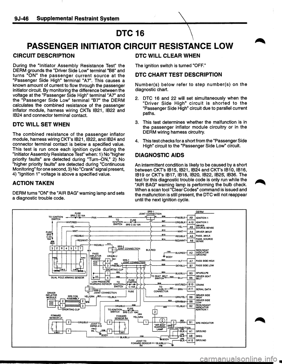
9J-46 Supplemental Restraint System
DTC 16
PASSENGER INITIATOR CIRCUIT RESISTANCE LOW
CIRCUIT DESCRIPTION
During the "Initiator Assembly Resistance Test" the
DERM grounds the "Driver
Side Low" terminal "B8" and
turns "ON" the passenger current source at the
"Passenger Side High" terminal "A7". This causes a
known amount of current to
flow through the passenger
initiator circuit. By monitoring the difference between the
voltage at the "Passenger Side High" terminal "A7" and
the "Passenger
Side Low" terminal "B7" the DERM
calculates the combined resistance of the passenger
inflator module, harness wiring CKTs IB21, IB22 and
IB24 and connector terminal contact.
DTC WILL SET WHEN
The combined resistance of the passenger inflator
module,
harness wiring CKT's IB21, IB22, and IB24 and
connector
terminal contact is below a specified value.
This test is run once each ignition cycle during the
"Initiator Assembly Resistance Test" when: 1) No "higher
priority
faults" are detected during "Turn-ON," 2) No
"higher priority
faults" are detected during "Continuous
Monitoring" for one second,
3) No "Crank" signal present,
4)
"Ignition 1" voltage is above a specified value.
ACTION TAKEN
DERM turns "ON" the "AIR BAG" warning lamp and sets
a diagnostic
trouble code.
1805
DTC WILL CLEAR WHEN
The ignition switch is turned "OFF."
DTC CHART TEST DESCRIPTION
Number(s) below refer to step number(s) on the
diagnostic chart.
2. DTC 16 and 22 will set simultaneously when the
"Driver Side High" circuit is shorted to the
"Passenger Side High" circuit due to parallel current
paths.
3. This test determines whether the malfunction is in
the passenger inflator module circuitry or in the
DERM wiring harness circuitry.
4. This test checks for a short from the "Passenger Side
High" circuit to the "Passenger Side Low" circuit.
DIAGNOSTIC AIDS
An intermittent condition is likely to be caused by a short
between CKT's
IB15, IB21, IB24 and CKT's IB10, IB16,
IB19
or CKT's IB17, IB18, IB20, IB22, IB25, IB36. The
test for this diagnostic
trouble code is only run while the
"AIR BAG" warning lamp is performing the bulb check.
When a scan
tool "Clear Codes" command is issued and
the
malfunction is still present, the DTC will not reappear
until the next ignition cycle.
SRS·1 JOINT CONNECTION 12 10 LBOe TO FUSE 1807 ~~~2~--SR~SC~-2+21-0A--~~--~---
IGNITION 1 IGNITION1 1111 1812 1813 DRIVER JeVLR
PASS. 36VLR
PASS. SOURCE
SENSE
REDUNDAT
INDICATOR
GROUND
PASS SIDE HIGH
PASS SIDE LOW
SERIAL DATA
SRS INDICATOR
•
Page 1674 of 1928
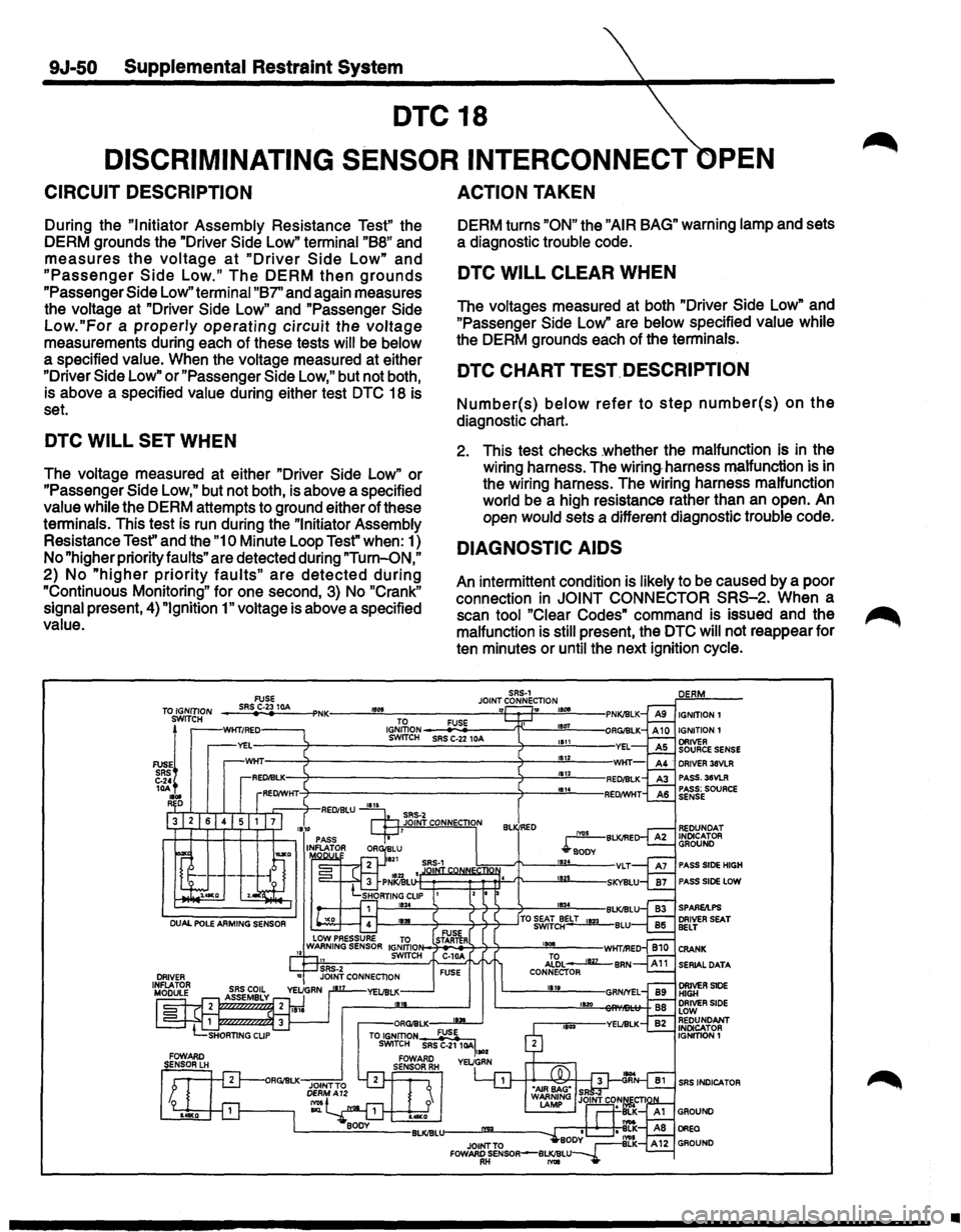
9J-50 Supplemental Restraint System
DTC 18
DISCRIMINATING SENSOR INTERCONNECT PEN
CIRCUIT DESCRIPTION
During the "Initiator Assembly Resistance Test" the
DERM grounds the "Driver
Side Low" terminal "88" and
measures the voltage at "Driver Side Low" and
"Passenger Side Low." The DERM then grounds
"Passenger Side Low" terminal "87" and again measures
the voltage at "Driver
Side Low" and "Passenger Side
Low."For a properly operating circuit the voltage
measurements during each of these tests will be below
a specified value. When the voltage measured at either
"Driver
Side Low" or "Passenger Side Low," but not both,
is above a specified value during either test
DTC 18 is
set.
DTC WILL SET WHEN
The voltage measured at either "Driver Side Low" or
"Passenger
Side Low," but not both, is above a specified
value
while the DERM attempts to ground either of these
terminals. This test is run during the
"Initiator Assembly
Resistance
Tesf' and the "1 o Minute Loop Test" when: 1)
No "higher priority faults" are detected during "Turn-ON,"
2) No "higher priority faults" are detected during
"Continuous Monitoring" for one second, 3) No "Crank"
signal present, 4) "Ignition 1" voltage is above a specified
value.
ACTION TAKEN
DERM turns "ON" the "AIR BAG" warning lamp and sets
a diagnostic trouble code.
DTC WILL CLEAR WHEN
The voltages measured at both "Driver Side Low" and
"Passenger
Side Low" are below specified value while
the DERM grounds each of the terminals.
DTC CHART TEST. DESCRIPTION
Number(s) below refer to step number(s) on the
diagnostic chart.
2. This test checks .whether the malfunction is in the
wiring harness. The wiring. harness malfunction is in
the wiring harness. The wiring harness malfunction
world be a high resistance rather than an open. An
open would sets a different diagnostic trouble code.
DIAGNOSTIC AIDS
An intermittent condition is likely to be caused by a poor
connection
in JOINT CONNECTOR SRS-2. When a
scan tool
"Clear Codes" command is issued and the
malfunction is
still present, the DTC will not reappear for
ten minutes or
until the next ignition cycle.
IGNITION1
DRIVER 3liVLR
PASS.38VLR
PASS; SOURCE SENSE
REDUNDAT INDICATOR GROUND
PASS SIDE HIGH
PASS SIDE LOW
SPARE/LPS
SERIAL DATA
SRS INDICATOR
•
Page 1678 of 1928
9J-54 Supplemental Restraint System
DTC21
DRIVER INITIATOR CIRCUIT RESISTANCE HIGH
CIRCUIT DESCRIPTION
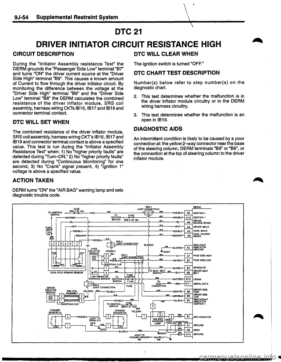
During the "Initiator Assembly resistance Test" the
DERM grounds the
"Passenger Side Low" terminal "B7"
and turns "ON" the driver current source at
the
"Driver
Side
High" terminal "B9". This causes a known amount
of Current to flow through the driver initiator circuit. By
monitoring the difference between the voltage at the
"Driver Side High" terminal "B9" and the "Driver Side
Low'' terminal "B8" the DERM calculates the combined
resistance of the driver inflator module, SRS coil
assembly, harness wiring CKTs IB16, IB17 and IB19 and
connector terminal contact.
DTC WILL SET WHEN
The combined resistance of the driver inflator module,
SRScoilassembly, harness wiring
CKT's IB16, IB17 and
IB19 and connector terminal contact is above a specified
value. This test is run during the
"Initiator Assembly
Resistance
Test" when: 1) No "higher priority faults" are
detected during
"Turn-QN," 2) No "higher priority faults"
are detected during
"Continuous Monitoring" for one
second, 3) No
"Crank" signal present, 4) "Ignition 1"
voltage is above a specified value.
ACTION TAKEN
DERM turns "ON" the "AIR BAG" warning lamp and sets
diagnostic trouble code.
FUSE
TO IGNITION SRS C-2310A 11105 SWITCH
TO
IGNITlON SWITCH
~i SRS
C-24 lOA 1800 AD
DTC WILL CLEAR WHEN
The ignition switch is turned "OFF."
DTC CHART TEST DESCRIPTION
Number(s) below refer to step number(s) on the
diagnostic chart.
2. This test determines whether the malfunction is in
the driver inflator module circuitry or
in the DERM
wiring harness circuitry.
3. This test determines whether the malfunction is an
open in IB19.
DIAGNOSTIC AIDS
An intermittent condition is likely to be caused by a poor
connection at: the yellow
2-way connector near the base
of the steering column, DERM terminals
"B8" or "B9", or
the connection at the top of steering column to the driver
inflator module.
SRS·l JOINT CONNECTION
" FUSE SRS C-2210A
BL ED
1800
1807 1111 1812 1113 11114
IGNITION! IGNITION 1
DRIVER 36VLR PASS. 36VLR PASS. SOURCE
SENSE
REDUNDAT INDICATOR GROUND
SRS·1 PASS SIDE HIGH
PASS SIDE LOW
IB34
1831 FUSE STARTER C-10A
SERIAL DATA FUSE
11120
1803
SRS INDICA TOR
•
Page 1680 of 1928
9J-56 Supplemental Restraint System
DTC22
DRIVER INITIATOR CIRCUIT RESISTANCE LOW
CIRCUIT DESCRIPTION
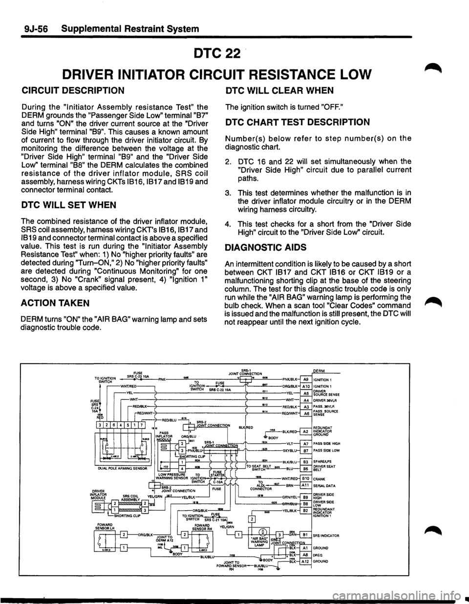
During the "Initiator Assembly resistance Test" the
DERM grounds the "Passenger
Side Low" terminal "B7"
and turns "ON" the driver current source at the "Driver
Side High" terminal "B9". This causes a known amount
of current to flow through the driver initiator circuit. By
monitoring the difference between the voltage at the
"Driver Side High" terminal "B9" and the "Driver Side
Low"
terminal "B8" the DERM calculates the combined
resistance of the driver inflator module, SRS coil
assembly, harness wiring CKTs IB16, IB17 and IB19 and
connector terminal contact.
DTC WILL SET WHEN
The combined resistance of the driver inflator module,
SRS coil assembly, harness wiring CKT's IB16, IB17 and
IB19 and connector terminal contact is above a specified
value. This test is run during the
"Initiator Assembly
Resistance
Test" when: 1) No "higher priority faults" are
detected during
"Turn-ON," 2) No "higher priority faults"
are detected during "Continuous Monitoring" for one
second,
3) No "Crank" signal present, 4) "Ignition 1"
voltage is above a specified value.
ACTION TAKEN
DERM turns "ON" the "AIR BAG" warning lamp and sets
diagnostic trouble code.
DTC WILL CLEAR WHEN
The ignition switch is turned "OFF."
DTC CHART TEST DESCRIPTION
Number(s) below refer to step number(s) on the
diagnostic chart.
2. DTC 16 and 22 will set simultaneously when the
"Driver Side High" circuit due to parallel current
paths.
3. This test determines whether the malfunction is in
the driver inflator module circuitry or in the DERM
wiring harness circuitry.
4. This test checks for a short from the "Driver Side
High"
circuit to the "Driver Side Low'' circuit.
DIAGNOSTIC AIDS
An intermittent condition is likely to be caused by a short
between CKT
IB17 and CKT IB16 or CKT IB19 or a
malfunctioning shorting
clip at the base of the steering
column. The test for this diagnostic trouble code is only
run while the "AIR BAG" warning lamp is performing the
bulb check. When a scan tool
"Clear Codes" command
is issued and the malfunction is
still present, the DTC will
not reappear until the next ignition cycle.
SAS·1 JOINT CONNECTlON FUSE SASC-2310A -. IGNITION 1 IGJ,\\oN FUSE SWrrtH SRS C-22 10A
DRIVER 38VLR PASS.30VLA PASS. SOURCE SENSE
REDUNOAT INOtcATOR GROUND
PASS SIDE HIGH PASS SIDE LOW
SPAREAPS
SERIAL DATA
DRIVER SIDE HIGH DRIVER SIDE LOW REDUNDANT INDICATOR
IGNITION 1
SRS INDICATOR
..