wiring ISUZU TROOPER 1995 Manual Online
[x] Cancel search | Manufacturer: ISUZU, Model Year: 1995, Model line: TROOPER, Model: ISUZU TROOPER 1995Pages: 1928
Page 983 of 1928
AUTOMATIC TRANSMISSION (4L30-E) 1 A-111
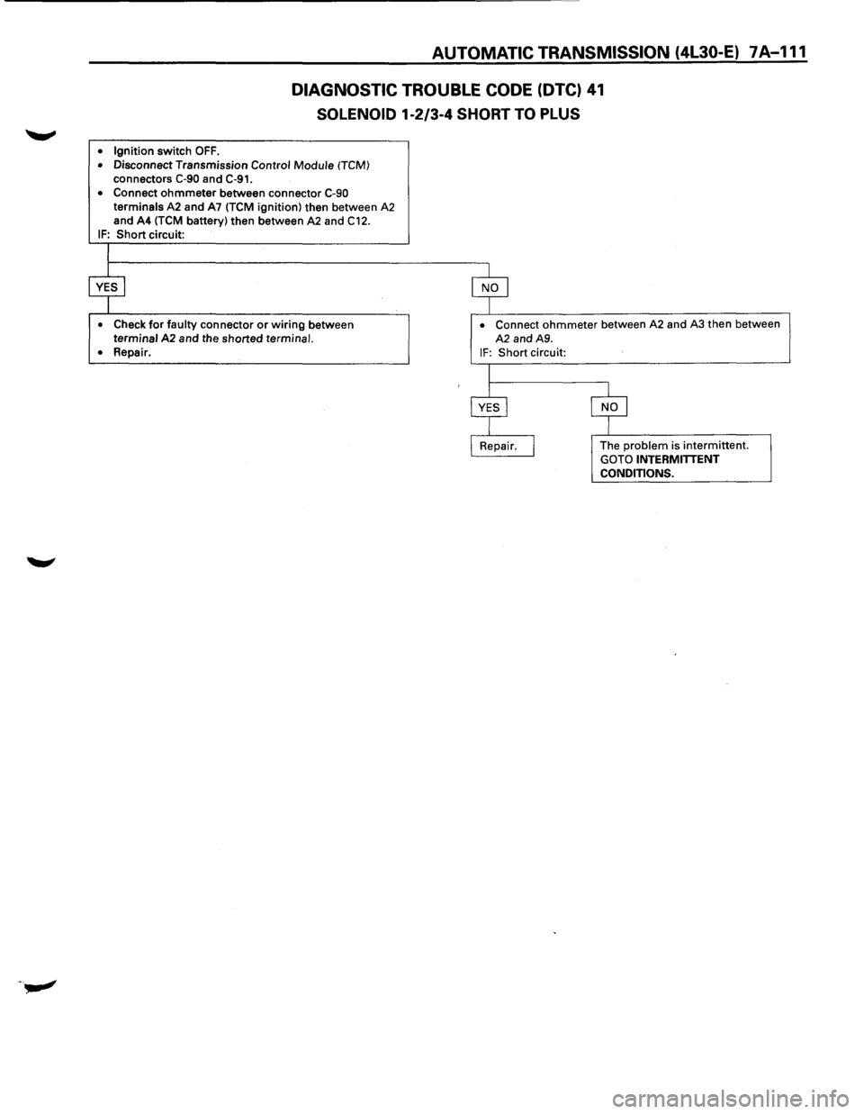
DIAGNOSTIC TROUBLE CODE (DTC) 41
SOLENOID 1·2/3-4 SHORT TO PLUS
• Ignition switch OFF.
• Disconnect Transmission Control Module (TCM)
connectors C-90 and C-91.
• Connect ohmmeter between connector C-90 terminals A2 and A7 (TCM ignition) then between A2 and A4 (TCM battery) then between A2 and C12.
IF: Short circuit:
• Check for faulty connector or wiring between terminal A2 and the shorted terminal.
• Repair.
• Connect ohmmeter between A2 and A3 then between
A2 and A9.
IF: Short circuit:
The
problem is intermittent. GOTO INTERMITTENT
CONDITIONS.
Page 985 of 1928
AUTOMATIC TRANSMISSION (4L30-E) 7A-113
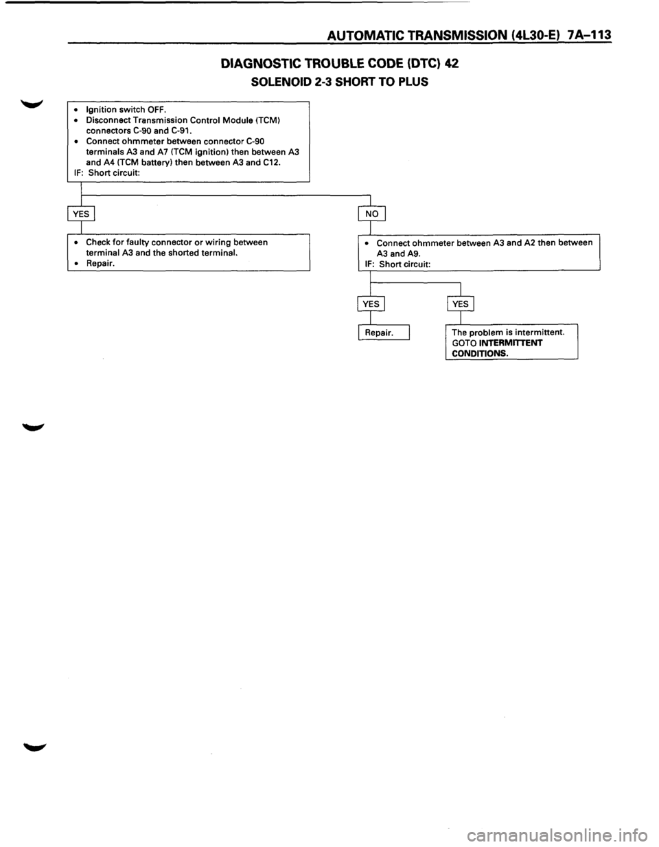
DIAGNOSTIC TROUBLE CODE (DTC) 42
SOLENOID 2-3 SHORT TO PLUS
• Ignition switch OFF.
• Disconnect Transmission Control Module (TCM)
connectors C-90 and C-91.
• Connect ohmmeter between connector C-90 terminals A3 and A7 (TCM ignition) then between A3
and A4 (TCM battery) then between A3 and C12.
IF: Short circuit:
• Check for faulty connector or wiring between terminal A3 and the shorted terminal.
•
Repair.
• Connect ohmmeter between A3 and A2 then between
A3 and A9.
IF: Short circuit:
The
problem is intermittent. GOTO INTERMmENT CONDITIONS.
Page 987 of 1928
AUTOMATIC TRANSMISSION (4L30•E) 7A-115
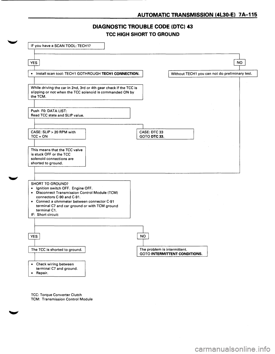
IF you have a SCAN TOOL: TECH1?
$
DIAGNOSTIC TROUBLE CODE (OTC) 43
TCC HIGH SHORT TO GROUND
$
• Install scan tool: TECH1 GOTHROUGH TECH1 CONNECTION . I Without TECH1 you can not do preliminary test.
While driving the car in 2nd, 3rd or 4th gear check if the TCC is slipping or not when the TCC solenoid is commanded ON by the TCM.
Push FO: DATA LIST:
I Read TCC state and SLIP value.
CASE: SLIP
> 20 RPM with I CASE: DTC 33
I TCC =ON GOTO DTC33.
This means that the TCC valve is stuck OFF or the TCC solenoid connections are shorted to ground.
SHORT TO GROUND?
• Ignition switch OFF. Engine OFF .
• Disconnect Transmission Control Module ITCM) connectors C-90 and C-91.
• Connect a ohmmeter between connector C-91 terminal C7 and car ground or with TCM ground terminal C1.
IF: Short circuit:
~ $
The TCC is shorted to ground. I The problem is intermittent.
I GOTO INTERMITTENT CONDITIONS.
• Check wiring between terminal C7 and ground.
• Repair .
TCC: Torque Converter Clutch
TCM: Transmission Control Module
I
Page 989 of 1928
AUTOMATIC TRANSMISSION (4L30-E) 7A-117
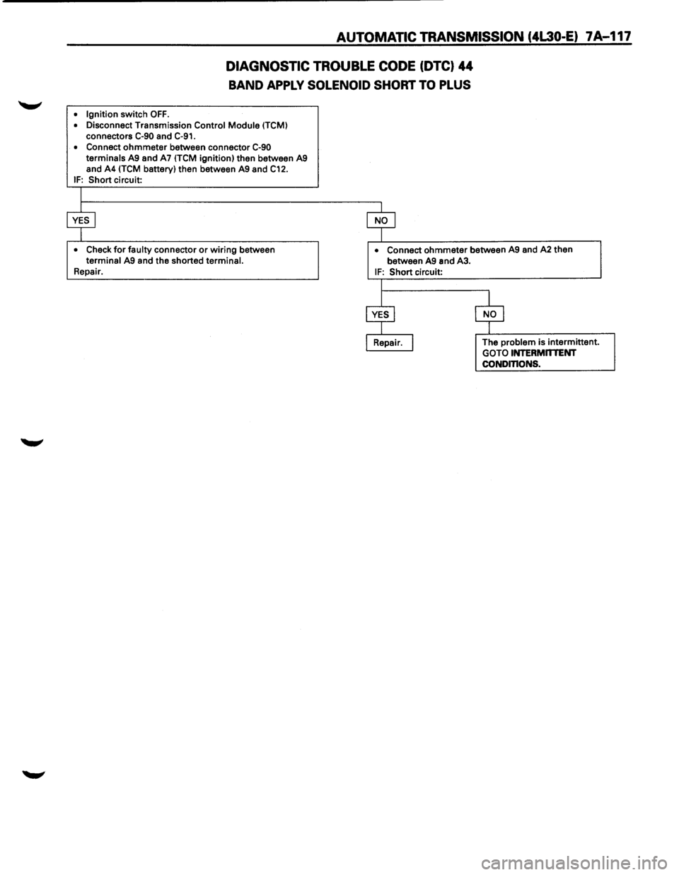
DIAGNOSTIC TROUBLE CODE (DTC) 44
BAND APPLY SOLENOID SHORT TO PLUS
• Ignition switch OFF.
• Disconnect Transmission Control Module (TCM)
connectors C-90 and C-91.
• Connect ohmmeter between connector C-90 terminals A9 and A7 ITCM ignition) then between A9
and A4 (TCM battery) then between A9 and C12. IF: Short circuit:
• Check for faulty connector or wiring between terminal A9 and the shorted terminal. Repair.
• Connect ohmmeter between A9 and A2 then
between A9 and A3.
IF: Short circuit:
The
problem is intermittent.
GOTO INTERMnTENT CONDinONS.
Page 991 of 1928
AUTOMATIC TRANSMISSION (4L30-E) 7A-119
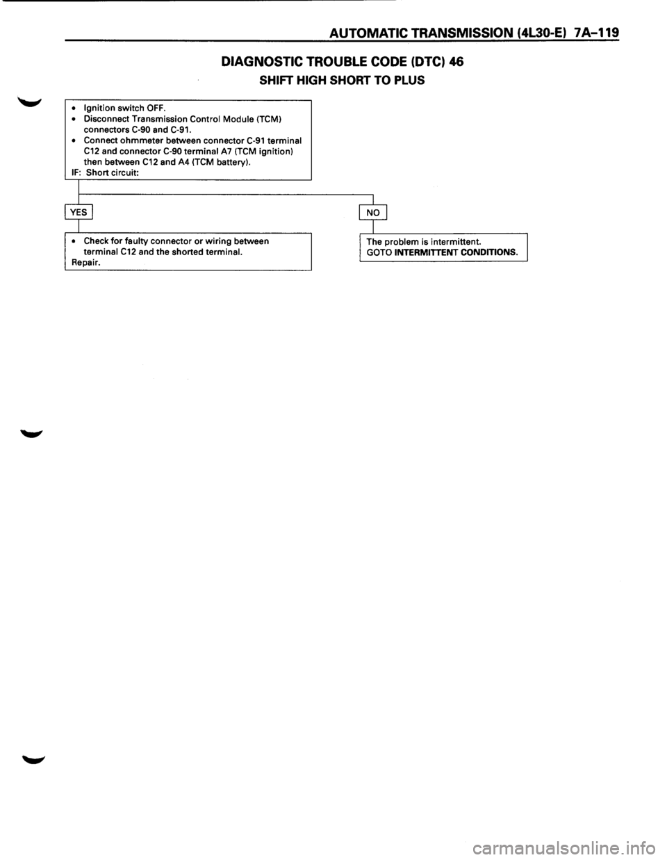
DIAGNOSTIC TROUBLE CODE (DTC) 46
SHIFT HIGH SHORT TO PLUS
• Ignition switch OFF .
• Disconnect Transmission Control Module (TCM) connectors C-90 and C-91.
• Connect ohmmeter between connector C-91 terminal C12 and connector C-90 terminal A7 (TCM ignition)
then between C12 and A4 (TCM battery). IF: Short circuit:
I
$ $
• Check for faulty connector or wiring between I The problem is intermittent. J terminal C12 and the shorted terminal.
GOTO INTERMITTENT CONDITIONS. Repair.
Page 996 of 1928
7A-124 AUTOMATIC TRANSMISSION (4L30-E)
DIAGNOSTIC TROUBLE CODE (DTC) 53
MODE SWITCH IN P OR N OR R BAD POSITION
This DTC does NOT flash the CHECK TRANS
indicator and does NOT set the BACKUP MODE.
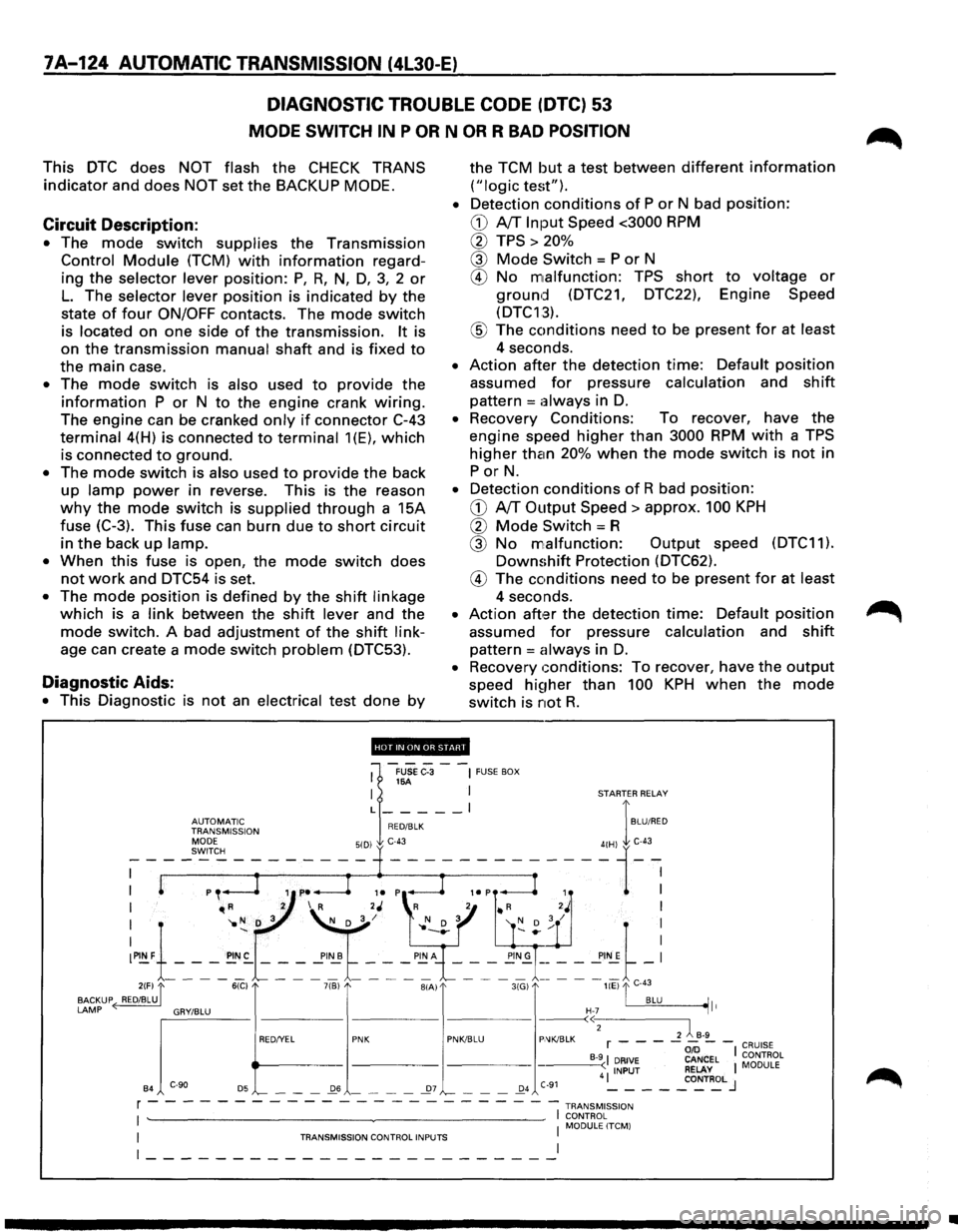
Circuit Description:
• The mode switch supplies the Transmission
Control Module (TCM) with information regard
ing
the selector lever position: P, R, N, D, 3, 2 or
L. The selector lever position is indicated by the
state
of four ON/OFF contacts. The mode switch
is located on one side of the transmission. It is
on
the transmission manual shaft and is fixed to
the main case.
• The mode switch is also used to provide the
information P or N to the engine crank wiring.
The engine can be cranked only if connector C-43
terminal 4(H) is connected to terminal 1(E), which
is connected to ground.
• The mode switch is also used to provide the back
up lamp power in reverse. This is the reason
why the mode switch is supplied through a 15A
fuse
(C-3). This fuse can burn due to short circuit
in the back up lamp.
•
When this fuse is open, the mode switch does
not work and DTC54 is set.
• The mode position is defined by the shift linkage
which is a link between the shift lever and the
mode switch. A bad adjustment of the shift link
age can create a mode switch problem (DTC53).
Diagnostic Aids:
• This Diagnostic is not an electrical test done by
the TCM but a test between different information
("logic test").
•
Detection conditions of P or N bad position:
CD A/T Input Speed <3000 RPM
0 TPS > 20%
@ Mode Switch = P or N
® No malfunction: TPS short to voltage or
ground (DTC21, DTC22), Engine Speed
(DTC13).
® The conditions need to be present for at least
4 seconds.
• Action after the detection time: Default position
assumed for pressure calculation and shift
pattern =always in D.
• Recovery Conditions: To recover, have the
engine speed higher than 3000 RPM with a TPS
higher than 20% when the mode switch is not in
PorN.
• Detection conditions of R bad position:
CD A/T Output Speed> approx. 100 KPH
0 Mode Switch= R
@ No malfunction: Output speed (DTC11).
Downshift Protection (DTC62).
® The conditions need to be present for at least
4 seconds.
• Action aft,:H the detection time: Default position
assumed for pressure calculation and shift
pattern = always in D.
• Recovery conditions: To recover, have the output
speed hi~1her than 100 KPH when the mode
switch is not R.
'''·"'·'lllfHJi'.!d'
1
-FUSe C-3 --~ FUSE BOX 16A I I STARTER RELAY
L _____ l I
~~J~Jr'~~~ION RED/BLK BLU/RED
I "'R 2 I R 2J 'R 2 • R 2J I
I '1o N D 3 ~/ l' N D 3 '( D ; / I
:~1-_-_-_~:-~ ~ ~'~t ~-: ~"~\_-_-~-_!!;~= = = ==~-: 2(F) "[ 6(C) 7(B) BIA) 3(G) liE) "'I C-43
BACKUP ( RED/BLU. . BLU ~It
LAMP ~'"""" "'""" "' e>
B4 '-- - -_Q6 - - - -_27 '-- - -_Q4 C-91 4 ~ - - -_co~T~L J
r - - - - - - - - - - - - - - - - - --- -- -1 TRANsM1ss1oN
I ~~~0RL~LITCM) I TRANSMISSION CONTROL INPUTS I
~-----------------------~
•
Page 998 of 1928
7A-126 AUTOMATIC TRANSMISSION (4L30-E)
DIAGNOSTIC TROUBLE CODE (DTC) 54
MODE SWITCH ILLEGAL POSITION
This DTC flashes the CHECK TRANS indicator and
sets the BACKUP
MODE.
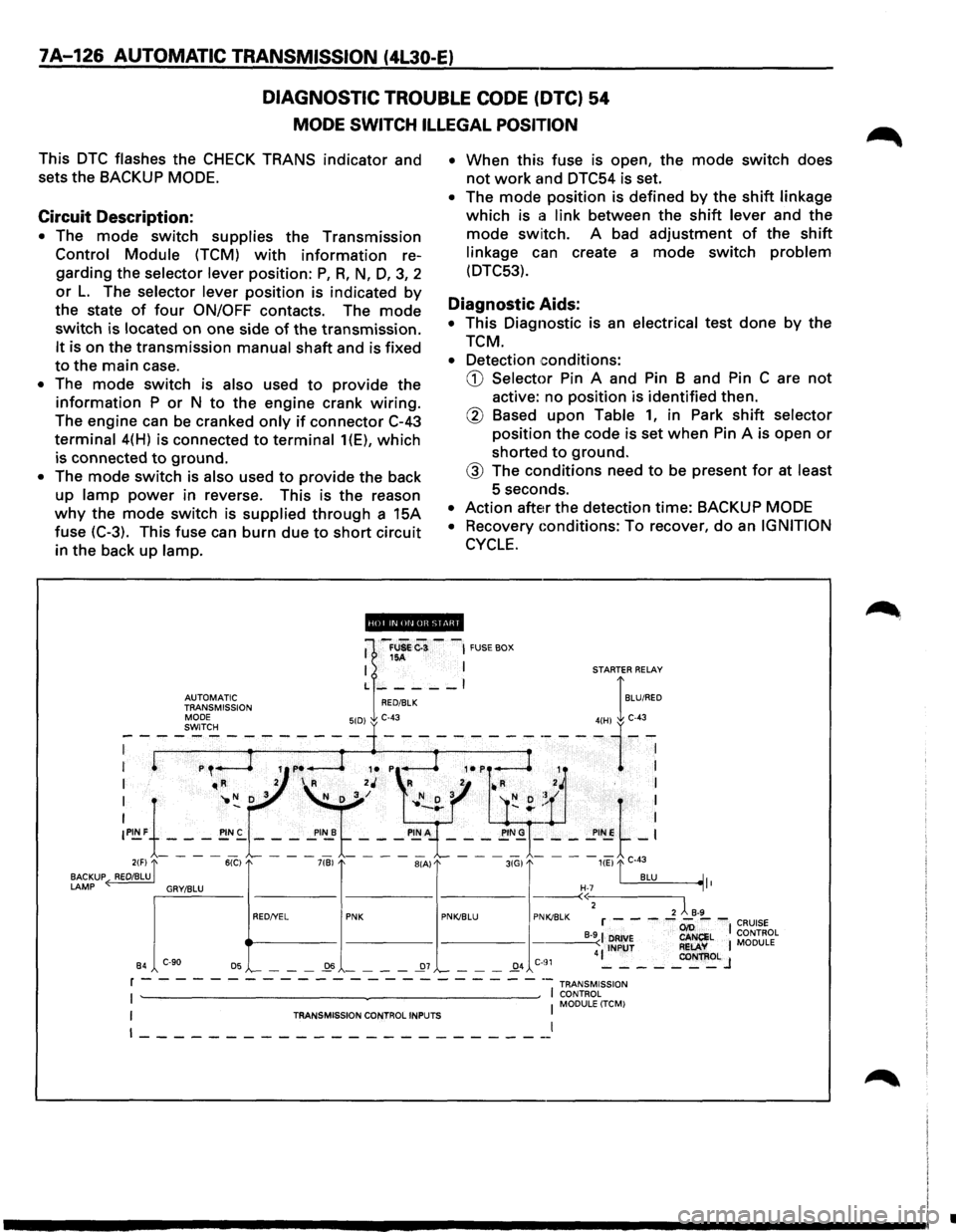
Circuit Description:
• The mode switch supplies the Transmission
Control Module (TCM) with information re
garding the
selector lever position: P, R, N, D, 3, 2
or L. The selector lever position is indicated by
the state of four ON/OFF contacts. The mode
switch is located on one side of the transmission.
It is on the transmission manual shaft and is fixed
to the main case.
• The mode switch is also used to provide the
information P or N to the engine crank wiring.
The engine can be cranked only if connector C-43
terminal 4(H) is connected to terminal 1(E), which
is connected to ground.
• The mode switch is also used to provide the back
up
lamp power in reverse. This is the reason
why the mode switch is supplied through a 15A
fuse (C-3). This fuse can burn due
to short circuit
in the back
up lamp. •
When
this fuse is open, the mode switch does
not work and DTC54 is set.
• The mode position is defined by the shift linkage
which is a link between the shift lever and the
mode switch. A bad adjustment of the shift
linkage can create a mode switch problem
(DTC53).
Diagnostic Aids:
• This Diagnostic is an electrical test done by the
TCM.
• Detection conditions:
CD Selector Pin A and Pin B and Pin C are not
active: no position is identified then.
@ Based upon Table 1, in Park shift selector
position the code is set when Pin A is open or
shorted to ground.
@ The conditions need to be present for at least
5 seconds.
• Action after the detection time: BACKUP MODE
•
Recovery Gonditions: To recover, do an IGNITION
CYCLE.
ii!Qpi.lifiiUI@ii!ll
•
Page 1018 of 1928
7A-146 AUTOMATIC TRANSMISSION (4L30-E)
INTERMITTENT CONDITIONS
If the TECH1 displays a diagnostic trouble code as
intermittent, or if after a test drive a DTC does not
reappear though the detection conditions for this
DTC are present: the problem is most likely a faulty
electrical connection or loose wiring. Terminals
and
grounds should always be the prime suspect.
lntermittents rarely occur inside sophisticated
electronic components such
as the TCM.
Use the
DTC information to understand which wires
and sensors are involved.
When an
intermittent problem is encountered,
check suspect circuits for:
(1) Poor terminal to wire connection.
(2) Terminals not fully seated in the connector
body (backed out).
(3) Improperly formed or damaged terminals.
(4) Loose, dirty, or corroded ground connections:
HINT: Any time you have an intermittent in
more than one circuit, check whether the circuits
share a
common ground connection.
(5) Pinched or damaged wires.
(6) Electro-Magnetic Interference (EMI):
HINT:
Check that all wires are properly routed
away from spark plug wires, distributor wires,
coil, and generator. Also check
for improperly
installed electrical options, such as lights, 2-way
radios, etc. Use
the
F3: SNAPSHOT mode of the TECH 1 to help
isolate the cause
of an intermittent fault. The
snapshot
mode will record information before and
after the problem occurs. Set the snapshot
to
"trigger" on the suspect DTC or, if you notice the
reported
symptom during test drive, trigger the
snapshot
manually.
(1) NOTE: When TECH1 is plugged the shifts are
always
done at the maximum pressure. This
means
that if you do SNAPSHOT while driving
you will! notice firm shifts.
After the snapshot has been triggered, command
the TECH1 to play back the flow of data recorded
from each of the various sensors. Signs of an
intermittent fault in a sensor circuit are sudden
unexplainable jump in data values out of the
normal range.
CASE:
problem still not solved GOTO TCM MEM
CAL REPLACEMENT.
•
Page 1022 of 1928
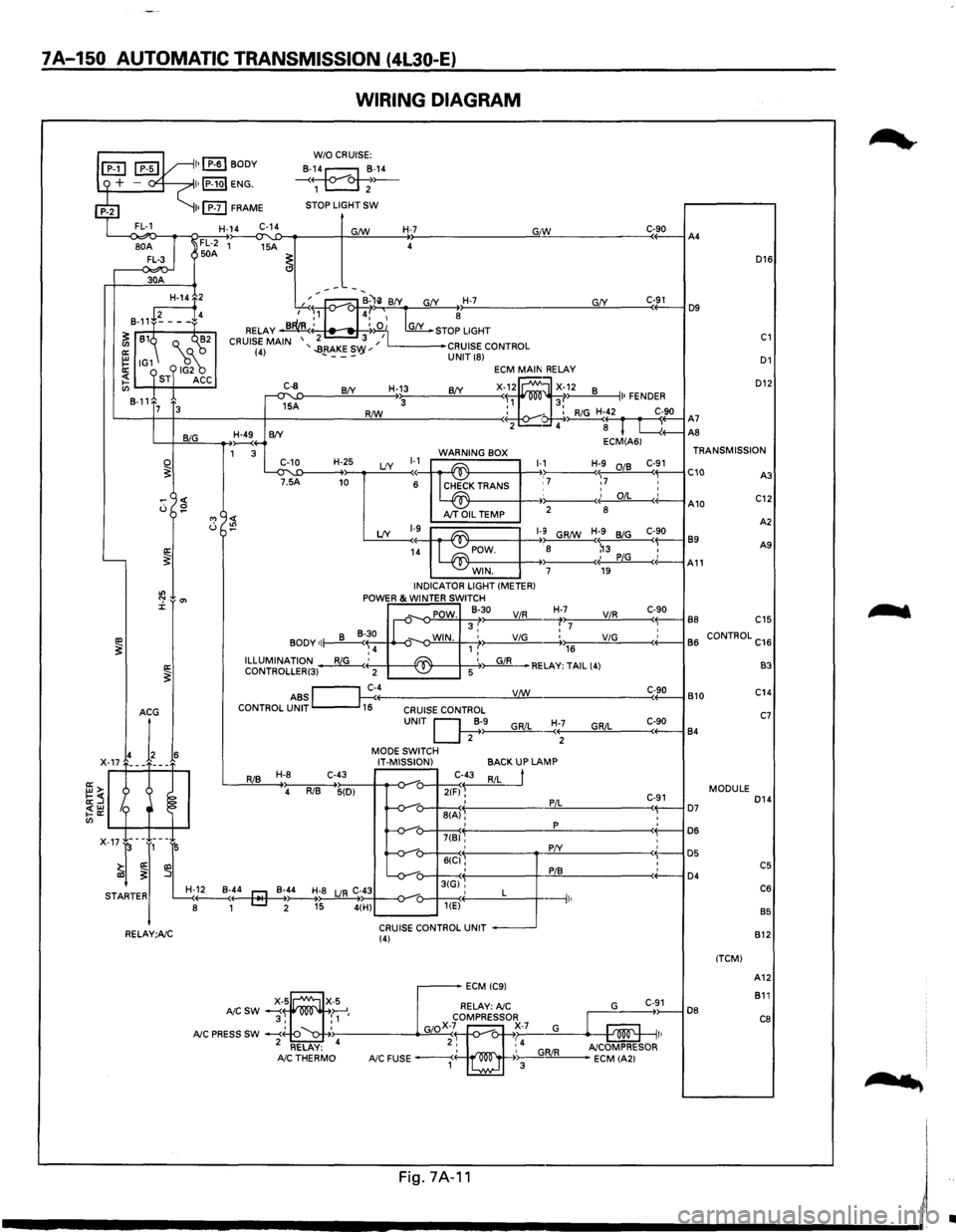
7A-150 AUTOMATIC TRANSMISSION (4L30-E)
WIRING DIAGRAM
L--<~o-~~~~~~--~~~----~~~----~~--------------~G"IW~------------C«-9_0--iA4
D16
30A
D12
GfY ---~:at--B-'li BfY G(Y H-7 ,...-..~., 4,' ~ ~
RELAY ~' ~:iO 1 [my_ STOP LIGHT
2 3 I CRUISE MAIN '..BRAKES '' L------•CRUISE CONTROL (4) - ---vy UNIT (8) D1
~2
8-11+~---f4
~ 81~ Q._ ("'~2
~ IG1 18~ ~ ST ACC en 8-11
C-91 D9
C1
ECM MAIN RELAY
X-f~ ~X~~2 8 II• FENDER R/W : - : RiG H-42 C-90 '-----t--t------+-------!:!Lll----------< • ~( r fl A7 2 4 8 L....{+--AS
C-8
~A
H-13 BfY BfY 3 7 3
L-+-JB~~I,_IG __ __....,~4-B(Y ECM(A61 1 3 WARNING BOX TRANSMISSION
~T'~5'-'1:D----H-+~2~5 LfY ~~~ ~K TRANS 1-,17 Hr7 :~ C-~1 C10 C::
0 ~
"' <( u :!?
'----~
"' ":' 0'> J:
IXl ~ a: ~
I~ A10 AJT OIL TEMP 2
8
A
2
LfY 1-9~ ~1-9 GR/W H;9 BiG C-90 89 1~ POW. : 8 ~3 , A9
- -~· PiG c(-A11 WIN. 7 19 INDICATOR LIGHT (METER) POWER & WINTER SWITCH
_,. POW. 8-30 ViR H-,>,7:;-----'V"-'iR.!..,_ ___ c<-~9-0-l B8 C15 II-v 3, :7 • BODY of~~ ~-o-WIN. 1 ,' ViG -----.+.,.,176 __ ____;;V.:..;iG=-----<+'-----1 B
6 CONTROL C16 ,4 ILLUMINATION~' ~ '~RELAY: TAIL (4) CONTROLLER(3) 2 -~ 5
ABS ~c~4----------------__yV:J..:!:!._/W ______________ ___:C<-~9:..::0-l B 10 CONTROL UNIT 16 CRUISE CONTROL
RiB H-8 C-43
4 RiB 5(D)
UNIT Q;·>-9------"G,_,Ri_,L_~:+--;-----'G""R""iL::,_ ___ c,-+-9-0----j 84
MODE SWITCH
IT-MISSION)
C-43
2(F) ~ ' 8(A), '
BACKUP LAMP
RiL
t
PiL
p
C-91 ( D7 : D6
B3
C14
C7
MODULE D14
: D5 : C5 ( D4 C6
B5
7(B)'
X-17-l-~J,-~L -v-: 6((:1§': :
r! -v-u-3tGi'', STARTER H-~..._:4---4r::J-Mo~-_B~;~;8 LJR C;~434--o-_,_-o---+---<·' L ---1 8 1 [::::J 2 15 4(H) u---~< 1 '
CRUISE CONTROL UNIT RELAY;A/C (4)
DB
(TCM) 812
A12
811
C8
....
'
Fig.7A·11 I
------------------------~~
•
Page 1023 of 1928
A4
D16
D9
C1
D1
D12
A7
AB
TRANSMISSION
A3 C10 C12
B9
A2
All A9 A10
BB C15
B6 C16
CONTROL
B3
B10 C14
C7
B4
D14
MODULE
D7 D6
D5
C5 D4 C6
B5
B12
(TCMI
A12 B11
DB
CB
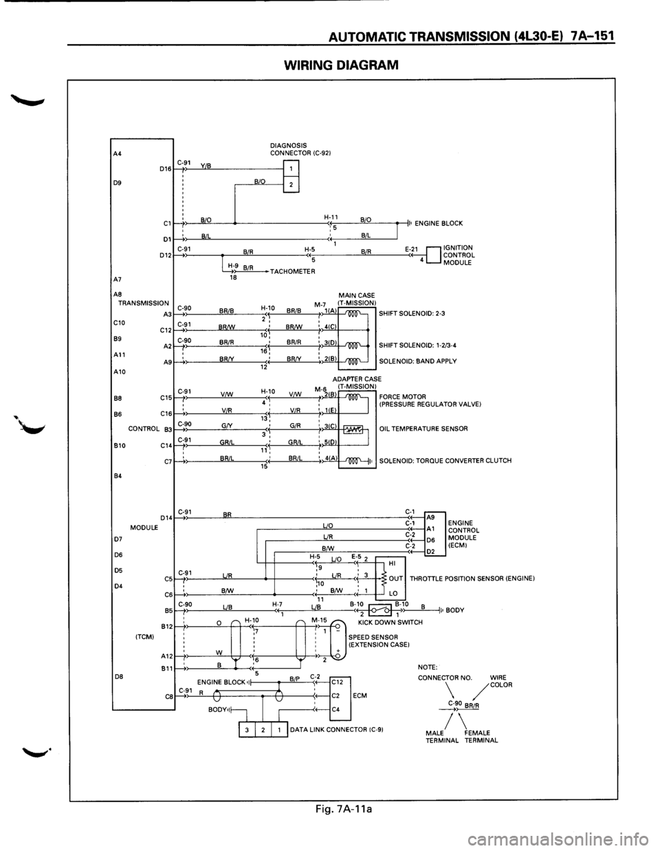
AUTOMATIC TRANSMISSION (4l30-E) 7 A-151
WIRING DIAGRAM
DIAGNOSIS
CONNECTOR (C-921 C-91
1: : j
B/0 B
I
I B/L
C-91 BIR :
G9 BIR 18
C-90 BRIB )
C-91 ) BR!W
C-90
BRIR I
I BR/Y )
C-91 V/W
'
' VIR )
C-90 G/Y
C-91 GRIL ) '
' BRIL :
C-91 BR
C-91 UR
: B/W
C-90 LIB )
;&"
r-r ,7 ' '
' '
' '
rt' w ,6
' B '
1---+: 5
ENGINE BLOCK •I C-91 R v
BODY•I~
H-11 B/0
'::5 B/L
1
H-5 BIR
(( 5
J
II• ENGINE B LOCK
E-~1 GNITION
ONTROL
MODULE ( 4 c
TACHOMETER
H-10
BRIB 'I 2 I
,J BR!W
I BRIR 16, ' BR/Y (( 12
H-10
4 ~ VC:!:f._
,j VIR
' GIR 3, ' GRIL ,,'~ ' BRIL (( 15
H-7 ((1
---
'r
B/P
1
v
I
MAIN CASE M-71(1 IT-MISSION) /1 A -'m'-SHIFT SOLENOID: 2-3 I I 4(C
: 3(0 -'m'-SHIFT SOLENOID: 1-2 /3-4
:, 21B -'100"'--SOLENOID: BAND AP PLY
ADAPTER
CASE
M-6211 IT-MISSION) FORCE MOTOR I 2 B
~ : liE (PRESSURE REGULAT OR VALVE)
I : 31C rAAUr1 '-== : SID I :, 41A ~I•
uo
UR
B/W
H-5
E 1-5 2 ~9 LIO
'
OIL TEMPERATURES
SOLENOID:
TORQUE
C-1 ..---A9 C-1 A1 C-2 D6 C-2
.-----.£L HI .?
ENSOR
CONVERTER CLUTCH
ENGINE CONTROL
MODULE (ECMI
\,o LIR < 3 OUT THROTTLE P OSITION SENSOR (ENGINE) ; B/W
' 1 LO 11 B-~10 LIB B ( 2 1 ~) II• BODY
"] "" oow' ""''" 1 -
: SPEED SENSOR : (EXTENSION CASE I ' + 2 NOTE:
't]
CONNEC
C12
: C2 ECM
C4 TOR
NO. WIRE /COLOR
~90 BRIR
I 3 I 2 I 1 I DATA LINK CONNECTOR (C-91 / MALE FEMALE TERMINAL TERMINAL
Fig.
7A-11a