wiring ISUZU TROOPER 1995 Workshop Manual
[x] Cancel search | Manufacturer: ISUZU, Model Year: 1995, Model line: TROOPER, Model: ISUZU TROOPER 1995Pages: 1928
Page 1202 of 1928
8-12 CHASSIS ELECTRICAL
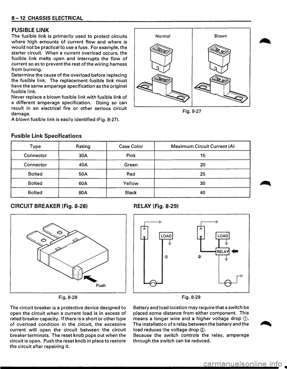
FUSIBLE LINK
The fusible link is primarily used to protect circuits
where high amounts
of current flow and where is
would not be practical to use a fuse. For example, the
starter circuit. When a current
overload occurs, the
fusible link melts open and interrupts the flow of
current so as to prevent the rest of the wiring harness
from burning.
Determine the cause
ofthe overload before replacing
the fusible link. The replacement fusible link must
have the same amperage specification as the original
fusible link.
Never replace a blown fusible link with fusible link of
a different amperage specification. Doing so can
result in an electrical fire or other serious circuit
damage.
A
blown fusible link is easily identified (Fig. 8-27).
Fusible Link Specifications
Normal Blown
Fig.
8-27
Type Rating
Case Color Maximum Circuit Current (A)
Connector
30A Pink 15
Connector 40A Green 20
Bolted 50 A Red 25
Bolted 60A Yellow 30
Bolted
BOA Black 40
CIRCUIT BREAKER (Fig. 8-28)
Push
Fig. 8-28
The circuit breaker is a protective device designed
to
open the circuit when a current load is in excess of
rated breaker capacity. If there is a short or other type
of overload condition in the circuit, the excessive
current
will open the circuit between the circuit
breaker
terminals. The reset knob pops out when the
circuit is open. Push the reset knob in
place to restore
the circuit after repairing it.
RELAY (Fig. 8-29)
Fig. 8-29
Battery and
load location may require that a switch be
placed some distance from either component. This
means a
longer wire and a higher voltage drop G).
The installation of a relay between the battery and the
load reduces the voltage drop®.
Because the switch controls the relay, amperage
through the switch can be reduced.
..
Page 1203 of 1928
CHASSIS ELECTRICAL 8-13
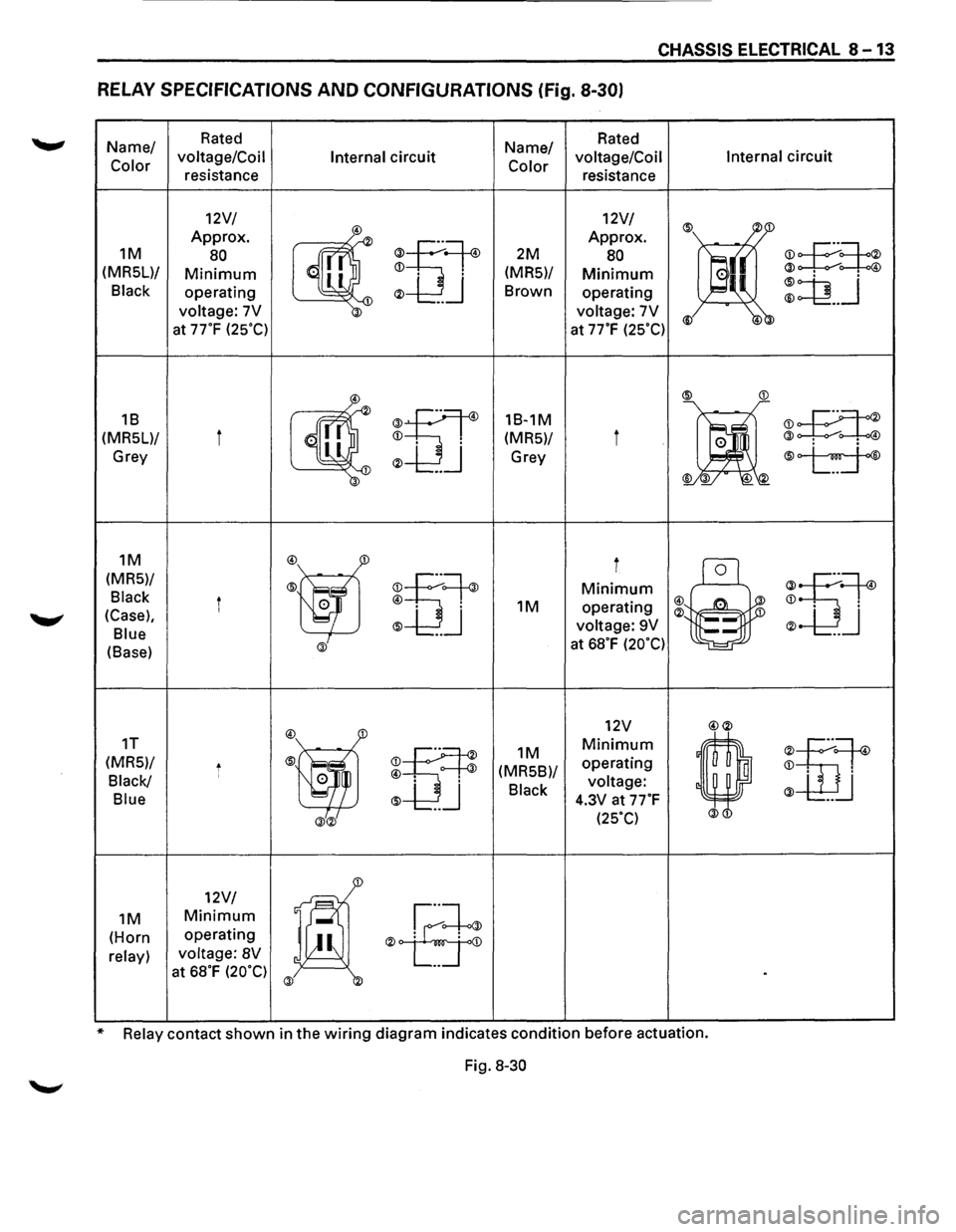
RELAY SPECIFICATIONS AND CONFIGURATIONS (Fig. 8-30)
Name/ Rated Name/ Rated
Color voltage/Coil
Internal circuit Color voltage/Coil Internal circuit
resistance resistance
12V/ 12V/
® ~1 Approx.
~
®u~
Approx.
~£:=!:~ 1M 80 2M 80
a(( (MRSL)/ Minimum
operating ® ... J Brown operating ::Q __ j
voltage: 7V voltage: 7V ® 4 at 77°F (2S°C) at 77"F (2SOC)
~
®
®tiT
18-1M
•
:E:t:
(MR5)/ i @ . . @
Grey Grey ®~ 4
1M
:@ff
i
®~
(MRS)/
rou~ Minimum
u~ Black i 0 @ . 1M operating ~ : 4
(Case), ® ... J ® 1
® J Blue voltage:
9V
(Base) @ at 68°F (20°C)
:@j
12V @®
1T
m
1M Minimum
'
m~
(MRS)/ t (MRSB)/ operating ~ : Black/ ' 0 @ voltage: @ u
Blue ® 4.3V at 77°F
@® (2SOC)
1
12V/
1@ .ff
1M Minimum
(Horn operating ®
at 68°F (20°C) @ .
* Relay contact shown in the wiring diagram indicates condition before actuation.
Fig.
8-30
Page 1465 of 1928
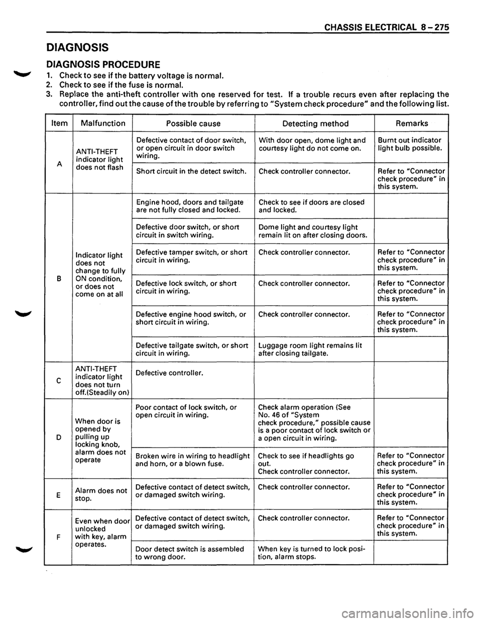
DIAGNOSIS
DIAGNOSIS PROCEDURE
.......,. 1. Check to see ifthe battery voltage is normal.
2. Check to see if the fuse is normal.
CHASSIS ELECTRICAL 8 -275
3. Replace the anti-theft controller with one reserved for test. If a trouble recurs even after replacing the
controller, find
out the cause of the trouble by referring to "System check procedure" and the following list.
Item Malfunction
Possible
cause Detecting method Remarks
Defective
contact of door switch,
With door open, dome light and Burnt
out indicator
ANTI-THEFT or open circuit in door switch courtesy light do not come on. light bulb possible.
indicator light wiring.
A does
not flash Short circuit in the detect switch.
Check controller connector. Refer to "Connector check procedure" in
this system.
Engine hood, doors and
tailgate Check to see if doors are closed are not fully closed and locked. and locked.
Defective door switch, or short Dome light and courtesy light circuit in switch wiring.
remain lit on after closing doors.
Indicator light Defective tamper switch, or short Check controller connector. Refer
to "Connector
does not circuit in wiring. check procedure" in
change to
fully this system.
B
ON condition, Defective lock switch, or short Check controller connector. Refer
to "Connector or does not come on at all circuit in wiring. check procedure" in
this system.
Defective engine hood switch, or Check
controller connector. Refer
to "Connector
short circuit in wiring. check
procedure" in
this system.
Defective
tailgate switch, or short Luggage room light remains lit circuit in wiring. after closing tailgate.
ANTI-THEFT
Defective controller.
c indicator light
does not turn off.(Steadily on) Poor contact
of lock switch, or Check alarm operation (See
When
door is open
circuit in wiring. No. 46 of "System
check procedure," possible cause
opened by
is a poor contact of lock switch or D pulling up
a open circuit in wiring. locking knob, alarm does not Broken wire in wiring to headlight Check to see if headlights go Refer
to "Connector operate
and horn, or a blown fuse. out. check procedure" in
Check
controller connector. this
system.
Alarm does not Defective contact of detect switch, Check controller connector.
Refer to "Connector
E
stop. or damaged switch wiring. check procedure" in
this system.
Even when
door Defective contact of detect switch, Check controller connector. Refer
to "Connector
unlocked
or damaged switch wiring. check procedure" in
F
with key, alarm this system.
operates. Door detect switch is
assembled When key is turned to lock posi-
to
wrong door. tion, alarm stops.
Page 1466 of 1928
8-276 CHASSIS ELECTRICAL
Item Malfunction
Possible cause
Detecting method Remarks
Alarm
does not
Defective contact of tailgate switch When luggage room light switch
G operate even or defective wiring. is turned on with tailgate open, with tailgate
luggage room light does not open
come on.
Even when
Defective contact
of tailgate detect Check controller connector. Refer to "Connector tailgate is open-
switch, or damaged wiring.
check procedure" in H ed with key, this system.
alarm does not
stop.
Even when en-
Damaged engine hood switch or gine hood is wiring.
opened with
I remote release,
alarm does not
operate
Even when
Defective contact
of starter switch. With starter switch turned to
J starter switch is II ACC" position, audio, cigarette
turned, alarm
lighter and door mirrors (on
does not stop
II ACC" circuit) do not operate.
Damaged
door switch, or a short After closing door, dome light
circuit in wiring. and courtesy light remain on.
K Indicator light
continues Damaged tamper switch, or a
Check controller connector. Refer to "Connector flashing
short circuit in wiring. check
procedure" in
this system.
..
Page 1625 of 1928
Supplemental Restraint System 9J-1
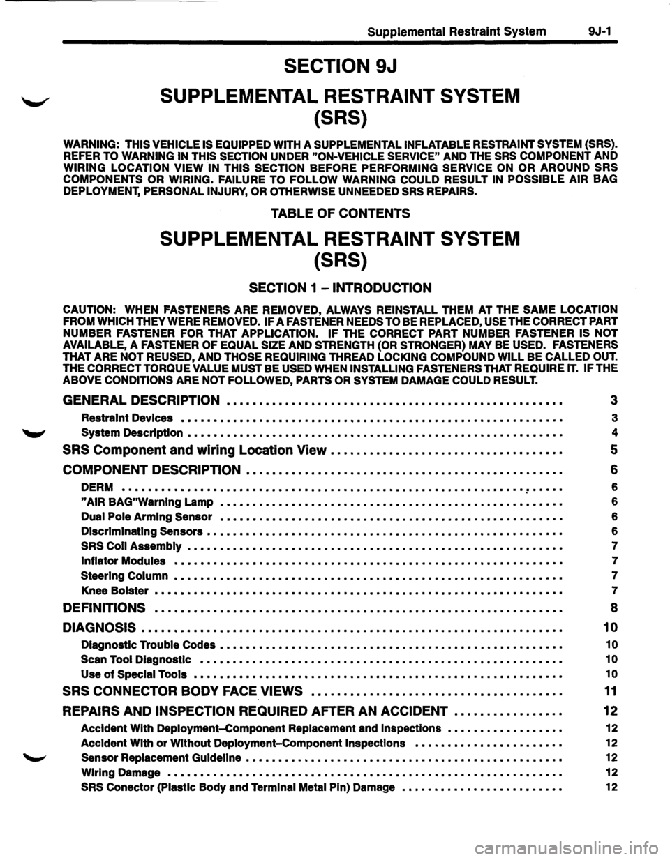
SECTION 9J
SUPPLEMENTAL RESTRAINT SYSTEM
(SRS)
WARNING: THIS VEHICLE IS EQUIPPED WITH A SUPPLEMENTAL INFLATABLE RESTRAINT SYSTEM (SRS).
REFER TO WARNING IN THIS SECTION UNDER "ON-VEHICLE SERVICE" AND THE SRS COMPONENT AND
WIRING LOCATION VIEW IN THIS SECTION BEFORE PERFORMING SERVICE ON OR AROUND SRS
COMPONENTS OR WIRING. FAILURE TO FOLLOW WARNING COULD RESULT IN POSSIBLE AIR BAG
DEPLOYMENT, PERSONAL INJURY, OR OTHERWISE UNNEEDED SRS REPAIRS.
TABLE OF CONTENTS
SUPPLEMENTAL RESTRAINT SYSTEM
(SRS)
SECTION 1 -INTRODUCTION
CAUTION: WHEN FASTENERS ARE REMOVED, ALWAYS REINSTALL THEM AT THE SAME LOCATION
FROM WHICH THEY WERE REMOVED. IF A FASTENER NEEDS TO BE REPLACED, USE THE CORRECT PART
NUMBER FASTENER FOR THAT APPLICATION. IF THE CORRECT PART NUMBER FASTENER IS NOT
AVAILABLE, A FASTENER OF EQUAL SIZE AND STRENGTH (OR STRONGER) MAY BE USED. FASTENERS
THAT ARE NOT REUSED, AND THOSE REQUIRING THREAD LOCKING COMPOUND WILL BE CALLED OUT.
THE CORRECT TORQUE VALUE MUST BE USED WHEN INSTALLING FASTENERS THAT REQUIRE IT. IF THE
ABOVE CONDITIONS ARE NOT FOLLOWED, PARTS OR SYSTEM DAMAGE COULD RESULT.
GENERAL DESCRIPTION • • • . • . . . . • . . . . . . . . . • . . . . • . . . . . . . . • . . . . . . . . • . . . . • . • . . 3
Restraint Devices • • • • • • • • • • • • • • • • • • • • • • • • • • .. • • • • • • • • • • • • • • • • • • • • • • • • • • • • • • • • 3
'W' System Description • • • • • • • • • • • • • • • • • • • • • • • • • • • • • • • • • • • • • • • • • • • • • • • • • • • • • • • • • • 4
SRS Component and wiring Location View . . . . . . • . . . . . . . . . . . • . . . . • . . . . . . . . . . • • 5
COMPONENT DESCRIPTION • • . .
. .
• . . • . .
.
• . . • . . . . . . . . . . . . . . . . . • . • . • . . . . • . • • . . 6
DERM ••••••••••••••••••\
••••••••••••••••••\
••••••••••••••••••\
•••••••• ~ • • • • • 6
"AIR BAG"Warnlng Lamp • • • • • • • • • • • • • • • • • • • • • • • • • • • • • • • • • • • • • • • • .. • • • • • • • • • • • • 6
Dual Pole Arming Sensor • • • • • • • • • • • • • • • • • • • • • • • • • • • • • • • • • • • • • • • • • • • • • • • • • • • • • 6
Discriminating Sensors • • • • • • • • • • • • • • • • • • • • • • • • • • • • • • • • • • • • • • • • • • • • • • • • • • • • • • • 6
SRS Coli Assembly • • • • • • • • • • • • • • • • • • • • • • • • • • • • • • • • • • • • • • • • • • • • • • • • • • • • • • • • • • 7
Inflator Modules • • • • • • • • • • • • • • • • • • • • • • • • • • • • • • • • • • • • • • • • • • • • • • • • • • • • • • • • • • • • 7
Steering Column • • • • • • • • • • • • • • • • • • • • • • • • • • • • • • • • • • • • • • • • • • • • • • • • • • • • • • • • • • • • 7
Knee Bolster • • • • • • • • • • • • • • • • • • • • • • • • • • • • • • • • • • • • • • • • • • • • • • • • • • • • • • • • • • • • • • • 7
DEFINITIONS • • . • . . • • • . • • . • • • • • . • . . • • . • . . . . . . . . . . . . . . . . . . . . . . . . . . . • . . . • • • • • • 8
DIAGNOSIS • • • • • • • • • • • • • • • • • • • • • • • • • • • . • • • • • • . • • • • • . . • • . . . . • • • • • . • • • • • • • • • • • 1 0
Diagnostic Trouble Codes • • • • • • • • • • • • • • • • • • • • • • • • • • • • • • • • • • • • • • • • • • • • • • • • • • • • • 1 0
Scan Tool Diagnostic • • • • • • • • • • • • • • • • • • • • • • • • • • • • • • • • • • • • • • • • • • • • • • • • • • • • • • • • 1 0
Use of Special Tools • • • • • • • • • • • • • • • • • • • • • • • • • • • • • • • • • • • • • • • • • • • • • • • • • • • • • • • • • 1 0
SRS CONNECTOR BODY FACE VIEWS . . . . . . . . . . . • . . . . . . . . . . . . . . . . . . . . . • . . . . . 11
REPAIRS AND INSPECTION REQUIRED AFTER AN ACCIDENT . . . . . • . . . . . . . . . . . 12
Accident With Deployment-component Replacement and Inspections • • • • • • • • • • • • • • • • • • 12
Accident With or Without Deployment-Component Inspections • • • • • • • • • • • • • • • • • • • • • • • 12
Sensor Replacement Guideline ••••••••• II • • • • • • • • • • • • • • • • • • • • • • • • • • • • • • • • • • • • • • • 12
Wiring Damage ••••••••••••••••••\
••• II • • • • • • • • • • • • • • • • • • • • • • • • • • • • • • • • • • • • • • • 12
SRS Conector (Plastic Body and Terminal Metal Pin) Damage • • • • • • • • • • • • • • • • • • • • • • • • • 12
Page 1630 of 1928
9J-6 Supplemental Restraint System <
COMPONENT DESCRIPTION
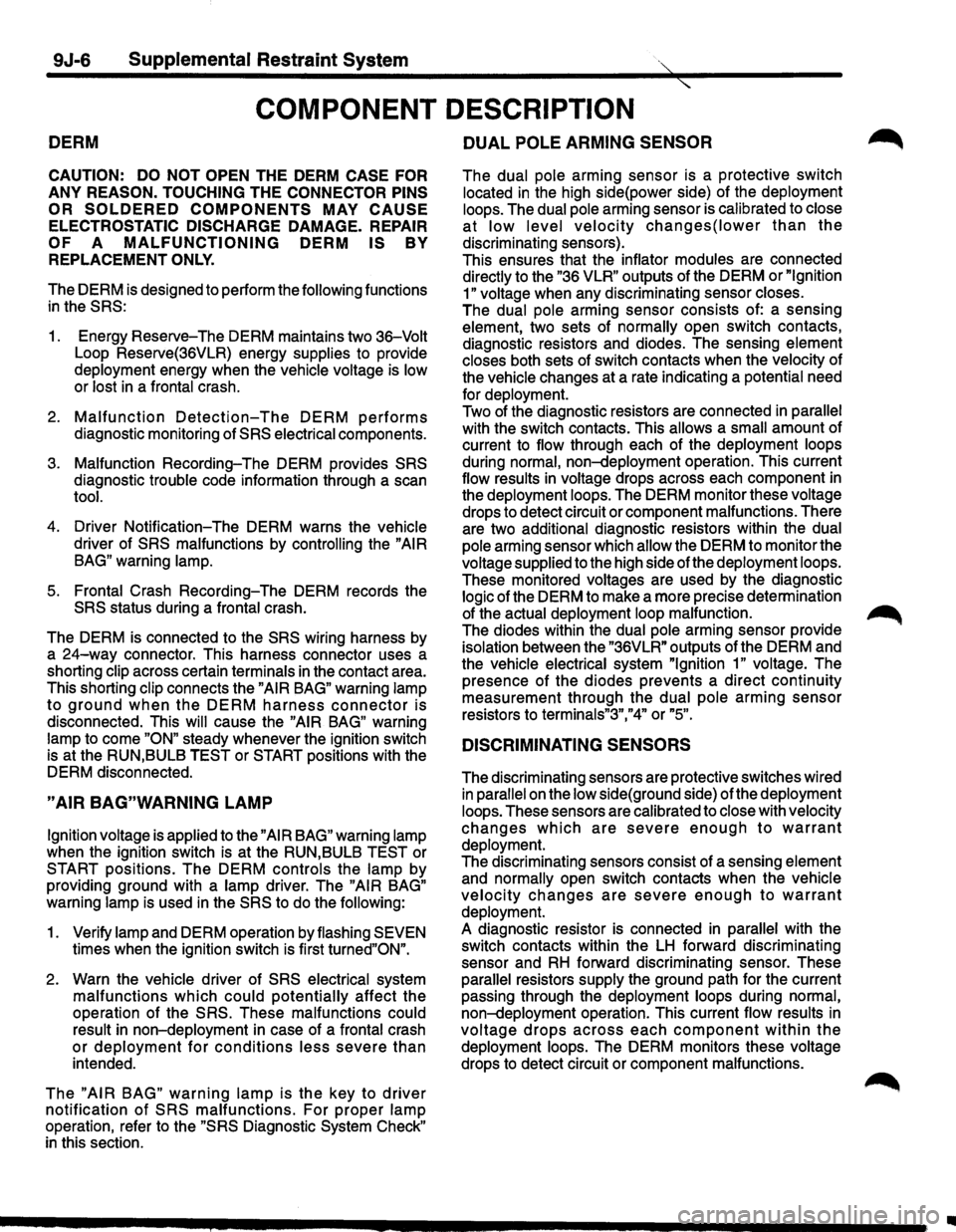
DERM
CAUTION: DO NOT OPEN THE DERM CASE FOR
ANY REASON. TOUCHING THE CONNECTOR PINS
OR SOLDERED COMPONENTS MAY CAUSE
ELECTROSTATIC DISCHARGE DAMAGE. REPAIR
OF A MALFUNCTIONING DERM IS BY
REPLACEMENT ONLY.
The DERM is designed to perform the following functions
in the SRS:
1. Energy Reserve- The DERM maintains two 36-Volt
Loop Reserve(36VLR) energy supplies to provide
deployment energy when the vehicle voltage is low
or lost in a frontal crash.
2. Malfunction Detection-The DERM performs
diagnostic monitoring of SRS electrical components.
3. Malfunction Recording- The DERM provides SRS
diagnostic trouble code information through a scan
tool.
4. Driver Notification- The DERM warns the vehicle
driver of SRS malfunctions by controlling the "AIR
BAG"
warning lamp.
5. Frontal Crash Recording- The DERM records the
SRS status during a frontal crash.
The DERM is connected to the
SRS wiring harness by
a
24-way connector. This harness connector uses a
shorting
clip across certain terminals in the contact area.
This shorting
clip connects the "AIR BAG" warning lamp
to ground when the DERM harness connector is
disconnected. This will cause the "AIR BAG" warning
lamp to come "ON" steady whenever the ignition switch
is at the RUN,BULB
TEST or START positions with the
DERM disconnected.
"AIR BAG"WARNING LAMP
Ignition voltage is applied to the "AIR BAG" warning lamp
when the ignition switch is at the RUN,BULB TEST or
START positions. The DERM controls the lamp by
providing ground with a
lamp driver. The "AIR BAG"
warning lamp is used in the SRS to do the following:
1. Verify lamp and DERM operation by flashing SEVEN
times when the ignition switch is first turned"ON".
2. Warn the vehicle driver of SRS electrical system
malfunctions which could potentially affect the
operation of the
SRS. These malfunctions could
result
in non-deployment in case of a frontal crash
or deployment for conditions less severe than
intended.
The "AIR BAG" warning lamp is the key to driver
notification of SRS malfunctions. For proper lamp
operation, refer to the "SRS Diagnostic System Check"
in this section.
DUAL POLE ARMING SENSOR ~
The dual pole arming sensor is a protective switch
located in the high side(power side) of the deployment
loops.
The dual pole arming sensor is calibrated to close
at low level velocity changes(lower than the
discriminating sensors).
This ensures that the
inflator modules are connected
directly to the "36 VLR" outputs of the DERM or "Ignition
1" voltage
when any discriminating sensor closes.
The dual pole arming sensor consists of: a sensing
element, two sets of normally open switch contacts,
diagnostic resistors and diodes. The sensing
element
closes
both sets of switch contacts when the velocity of
the
vehicle changes at a rate indicating a potential need
for
deployment.
Two of the diagnostic resistors are connected in parallel
with the switch contacts. This allows a small amount of
current to
flow through each of the deployment loops
during normal, non-deployment operation. This current
flow results in voltage drops across each component in
the
deployment loops. The DERM monitor these voltage
drops to detect circuit or component malfunctions. There
are two
additional diagnostic resistors within the dual
pole
arming sensor which allow the DERM to monitor the
voltage supplied to the high side ofthe deployment loops.
These monitored voltages are used by the diagnostic
logic of the DERM to make a more precise determination
of the
actual deployment loop malfunction. ~
The diodes within the dual pole arming sensor provide
isolation between the "36VLR" outputs of the DERM and
the
vehicle electrical system "Ignition 1" voltage. The
presence of the diodes prevents a direct continuity
measurement through the
dual pole arming sensor
resistors to
terminals"3","4" or "5".
DISCRIMINATING SENSORS
The discriminating sensors are protective switches wired
in parallel on the low side(ground side) of the deployment
loops.
These sensors are calibrated to close with velocity
changes which are severe enough to warrant
deployment.
The discriminating sensors consist of a sensing element
and normally open switch contacts when the vehicle
velocity changes are severe enough to warrant
deployment.
A diagnostic resistor is connected in parallel with the
switch contacts within the
LH forward discriminating
sensor and
RH forward discriminating sensor. These
parallel resistors supply the ground path for the current
passing through the
deployment loops during normal,
non-deployment operation. This current flow results in
voltage drops across each component within the
deployment loops. The DERM monitors these voltage
drops to detect circuit or component malfunctions.
II
Page 1631 of 1928
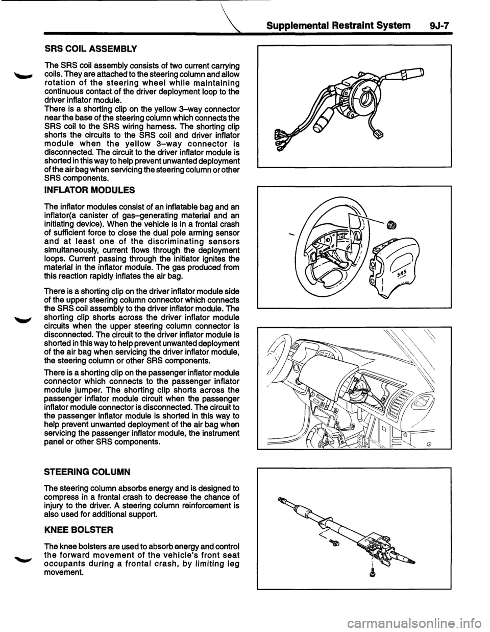
SRS COIL ASSEMBLY
The SRS coil assembly consists of two current carrying
coils. They are attached to the steering column and allow
rotation of the steering wheel while maintaining
continuous contact of the driver deployment loop to the
driver inflator module.
There is a shorting clip on the yellow
3-way connector
near the base of the steering column which connects the
SRS coil to the SRS wiring harness. The shorting clip
shorts the circuits to the
SRS coil and driver inflator
module when the yellow 3-way connector is
disconnected. The circuit to the driver inflator module is
shorted
in this way to help prevent unwanted deployment
of the air bag when servicing the steering column or other
SRS components.
INFLATOR MODULES
The inflator modules consist of an inflatable bag and an
inflator(a canister of gas-generating material and an
initiating device). When the vehicle is in a frontal crash
of sufficient force to close the dual pole arming sensor
and at least one of the discriminating sensors
simultaneously, current flows through the deployment
loops. Current passing through the initiator ignites the
material
in the inflator module. The gas produced from
this reaction rapidly inflates the air bag.
There is a shorting clip
on the driver inflator module side
of the upper steering column connector which connects
the
SRS coil assembly to the driver inflator module. The
shorting clip shorts across the driver inflator module
circuits when the upper steering column connector is
disconnected. The circuit to the driver inflator module is
shorted
in this way to help prevent unwanted deployment
of the air bag when servicing the driver inflator module,
the steering column
or other SRS components.
There is a shorting clip on the passenger inflator module
connector which connects to the passenger inflator
module jumper. The shorting clip shorts across the
passenger inflator module circuit when the passenger
inflator module connector is disconnected. The circuit to
the passenger inflator module is shorted in this way to
help prevent unwanted deployment of the air bag when
servicing the passenger inflator module, the instrument
panel or other
SRS components.
STEERING COLUMN
The steering column absorbs energy and is designed to
compress in a frontal crash to decrease the chance of
injury to the driver. A steering column reinforcement is
also used for additional support.
KNEE BOLSTER
The knee bolsters are used to absorb energy and control
the forward movement of the vehicle's front seat
occupants during a frontal crash, by limiting leg
movement.
Supplemental Restraint System 9J-7
Page 1632 of 1928
9J-8 Supplemental Restraint System
DEFINITIONS
AIR BAG -An inflatable cloth cushion designed to
deploy in certain frontal crashes. It supplements the
protection offered by the seat belts by distributing the
impact load more evenly over the vehicle occupant's
head and torso.
ASYNCHRONOUS -Performed in a non-periodic
fashion,i.e.no defined time or interval.
B+-Battery voltage, the voltage available at the battery
at the time of the indicated measurement. With the key
"ON" and the engine not running, the system voltage will
likely be between 12 and 12.5 volts. At idle the voltage
may be 14 to 16 volts. The voltage could be as low as 1
0
volts during engine cranking.
BULB
CHECK-The DERM will cause the "AIR BAG"
warning lamp to flash seven times and then go "OFF"
whenever the ignition switch transitions to the RUN
position from any other ignition switch position and no
malfunctions are detected.
"CONTINUOUS MONITORING"-Tests performed by
the DERM on the
SRS every 1 00 milliseconds while
"Ignition
1" voltage is in the normal operating voltage
range at the DERM.
DATA LINK CONNECTOR(DLC)-Formerly "ALDL'', a
connector which allows communication with an
off-board computer, such as a scan
tool.
DATUM LINE-A base line parallel to the plane of the
underbody or frame from which all vertical
measurements originate.
DEPLOY-To inflate the air bag.
DEPLOYMENT
LOOPS - The circuits which supply
current to the inflator modules to deploy the air bag.
DERM -Diagnostic
energy reserve module which
provides reserve energy to the deployment loops and
performs diagnostic monitoring of
all SRS components.
DIAGNOSTIC TROUBLE CODE(DTC) -Formerly
"Code,"a numerical designator used by the DERM to
indicate specific
SRS malfunctions.
DRIVER CURRENT SOURCE-An output of the DERM
which injects current into the driver inflator module circuit
during the "Initiator Assembly Resistance
Test."
DRIVER INFLATOR
MODULE-An assembly located in
the steering wheel hub consisting of an inflatable air bag,
an inflator and an initiator.
DUAL
POLE ARMING SENSOR-A sensor on the high
side(power side) of the deployment loops that is
calibrated to supply voltage to the inflator modules when
the vehicle velocity changes are severe enough to
warrant arming of the air bags in preparation for
deployment.
EEPROM -Electrically Erasable Programmable Read ~
Only Memory. Memory which retains its contents when
power
is removed from the DERM.
FORWARD LH DISCRIMINATING SENSOR-A sensor
on the low side(ground side) of the deployment loops
which is calibrated to ground the inflator modules when
the vehicle velocity changes are severe enough to
warrant deployment of the air bags.
FORWARD RH DISCRIMINATING SENSOR-A sensor
on the low side(ground side) of the deployment loops
which
is calibrated to ground the inflator modules when
the vehicle velocity changes are severe enough
to
warrant deployment of the air bag.
FORWARD LH SENSOR Eng-Room HARNESS-An
assembly of two correct carrying wires which connects
the Forward
LH discriminating sensor to SRS harness.
FORWARD RH SENSOR Eng-Room HARNESS
JUMPER-An assembly of two current carrying wires
which connects the Forward
RH discriminating sensor to
the
SRS harness.
HIGHER PRIORITY FAULT-Each diagnostic trouble
code
is assigned a priority based on the detectability with
other DTCs present. The priority corresponds to the
detectability of the malfunction ONLY, and does NOT
relate to the criticality of the malfunction with respect to ~
deployment or non-deployment under any given
condition.
IGNITION CYCLE -The voltage at the PERM "Ignition
1"
inputs, with ignition switch "ON," is within the normal
operating voltage range for at least ten seconds before
turning ignition switch
"OFF."
IGNITION1
-A battery voltage(B+)circuit which is only
powered with the ignition switch in the RUN,BULB
TEST,or START positions.
INITIATOR-The electrical component inside the inflator
module which, when sufficient current flows, sets off the
chemical reaction that inflates the air bag.
"INITIATOR ASSEMBLY RESISTANCE TEST"-Tests
performed once each ignition cycle when no
malfunctions are detected during "Turn-ON" or
"Continuous Monitoring." This test checks for the correct
DERM configuration for the vehicle, shorts to
"Ignition 1"
in the deployment loops, high resistance or opens in the
"Driver
Side High," "Driver Side Low," "Passenger Side
High"
and "Passenger Side Low" circuits and measures
the resistance of the inflator assembly consisting of: 1)
Initiators, 2) SRS coil assembly(driver side only), 3)
Connectors and associated wiring.
NORMAL OPERATING VOLTAGE RANGE-The ~
voltage measured between the DERM "Ignition 1" ·
terminals and "Ground" terminals is between 7.25 and 16
volts.
•
Page 1633 of 1928
PASSENGER CURRENT SOURCE -An output of the
DERM which injects current into the passenger inflator
module circuit during the
~Initiator Assembly Resistance
'--"" Test."
PASSENGER INFLATOR MODULE -An assembly
located in the right side of the 1/P consisting of an
inflatable bag, an inflator and an initiator.
SCAN TOOL -An off-board computer used to read
diagnostic information from on-board computers via the
data
link connector.
SERIAL DATA -Information representing the status of
the
SRS.
SRS
-Supplemental Restraint System.
SRS COIL ASSEMBLY-An assembly of two current
carrying coils in the driver deployment loop that allows
the rotation of the steering wheel while maintaining the
continuous contact
of the driver deployment loop to the
driver inflator module.
SRS WIRING HARNESS-The wires and connectors
that electrically connect the components in the
SRS.
1 Supplemental Restraint System 9J-9
"10 MINUTE LOOP TEST' -Portions of the "Initiator
Assembly Resistance Test" are repeated every ten
minutes during an ignition cycle. These are the check for
shorts to
"Ignition 1" in the deployment loops and the
check for an open discriminating sensor interconnect
circuit.
''TURN-ON" -Test which the DERM performs on the
SRS once during each ignition cycle immediately after
"Ignition 1" voltage is applied to the DERM and before
"Continuous Monitoring."
36VLR-The 36-volt loop reserve energy supplies from
the DERM which provide deployment power when
vehicle voltage is
low or lost in a frontal crash.
36 VLR DELAY
-Changing of the 36 VLR power supplies
is
inhibited briefly during "Turn-ON." This allows
detection of certain malfunctions related to "Ignition 1"
voltage which cannot be tested with 36 volts present.
Page 1636 of 1928
9J-12 Supplemental Restraint System
REPAIRS AND INSPECTIONS REQUIRED AFTER AN
ACCIDENT
NOTE
• If
any SRS components are damaged, they must be
replaced. If SRS component mounting points are
damaged, they must be
replaced.
•
Never use SRS parts from another vehicle. This
does not
include remanufactured parts purchased
from an authorized
dealer; they may be used for SRS
repairs.
• Do not attempt to service discriminating sensors, the
dual pole arming sensor, the DERM, the SRS coil
assembly,
or the inflator modules. Service of these
items is by
replacement only.
•
Verify the part number of replacement inflator
modules.
CAUTION: PROPER OPERATION OF THE
SENSORS AND SUPPLEMENTAL RESTRAINT
SYSTEM (SRS) REQUIRES THAT ANY REPAIRS TO
THE VEHICLE STRUCTURE RETURN IT TO THE
ORIGINAL PRODUCTION CONFIGURATION.
DEPLOYMENT REQUIRES, AT A MINIMUM,
REPLACEMENT OF THE SENSORS, THE INFLATOR
MODULE,
AND DIMENSIONAL INSPECTION OF THE
STEERING COLUMN. ANY VISIBLE DAMAGE TO
THE DERM MOUNTING BRACKET(S) REQUIRES
REPLACEMENT, SENSORS MUST BE REPLACED,
AND THE
STEERING COLUMN MUST BE
DIMENSIONALLY INSPECTED, WHETHER
DEPLOYMENT
OCCURRED OR NOT.
ACCIDENT WITH DEPLOYMENT-COMPONENT
REPLACEMENT AND
INSPECTIONS
Certain SRS components must be replaced for damage
after a
frontal crash involving air bag deployment. Those
components are:
• Inflator modules.
• All
sensors. It is include among the Dual pole Arming
Sensor.
CAUTION
•
Refer to "Sensor Replacement Guidelines"
below for Important Information on sensor
replacement In both deployment and
non-deployment crashes.
• SRS coil assembly, Inspect wiring and connector for
any signs of scorching,
melting, or damage due to
excessive heat.
Replace if damaged. Refer to this in
section
3.
ACCIDENT WITH OR WITHOUT DEPLOYMENT
COMPONENT INSPECTIONS
Certain SRS and restraint system components must be
inspected after any crash, whether the air bag
deployed
or not. Those components are:
• Steering column-Dimensionally inspect per
"Checking Steering Column for Accident Damage" in
section 3.
• Sensors, if in the area of accident damage. If with
deployment, All sensors must be replaced.
CAUTION
•
Refer to "Sensor Replacement Guidelines"
below for Important information on sensor
replacement in both deployment and
non-deployment crashes.
• Knee bolsters and mounting points-Inspect for any
distortion, bending, cracking, or other damage.
• 1/P steering column reinforcement plate-Inspect for
any distortion, bending, cracking, or other damage.
• liP braces-Inspect for any distortion, bending,
cracking, or other damage.
~
• Seat belts and mounting points-Refer to "Seat Belts"
in SECTION 10.
SENSOR REPLACEMENT GUIDELINES
SRS sensor replacement policy requires replacement of
the all sensors, after crash Involving Air Bag
Deployment.
WIRING DAMAGE
If any SRS wire harness is damaged, it should be
replaced. Don't repair SRS HARNESS. It is replace only.
SRS CONNECTOR {PLASTIC BODY AND
TERMINAL METAL PIN) DAMAGE
If any connector or terminal in the SRS wire harness
(except
pigtails) is damaged, it should be replaced.
SRS WIRE PIGTAIL DAMAGE
If the wiring pigtail (a wire or wires attached directly to the
device,
not by a connector)is damaged, the entire
component(with pigtail)must be replaced. Examples of
"pigtail" components are the driver inflator module, the
passenger
inflator module, the discriminating sensors,
the
dual pole arming sensor and the SRS coil assembly. ~
SRS WIRE DAMAGE
If any wire except the pigtail is damaged, the wire should
be replaced.
Ill