wiring ISUZU TROOPER 1995 Workshop Manual
[x] Cancel search | Manufacturer: ISUZU, Model Year: 1995, Model line: TROOPER, Model: ISUZU TROOPER 1995Pages: 1928
Page 1045 of 1928
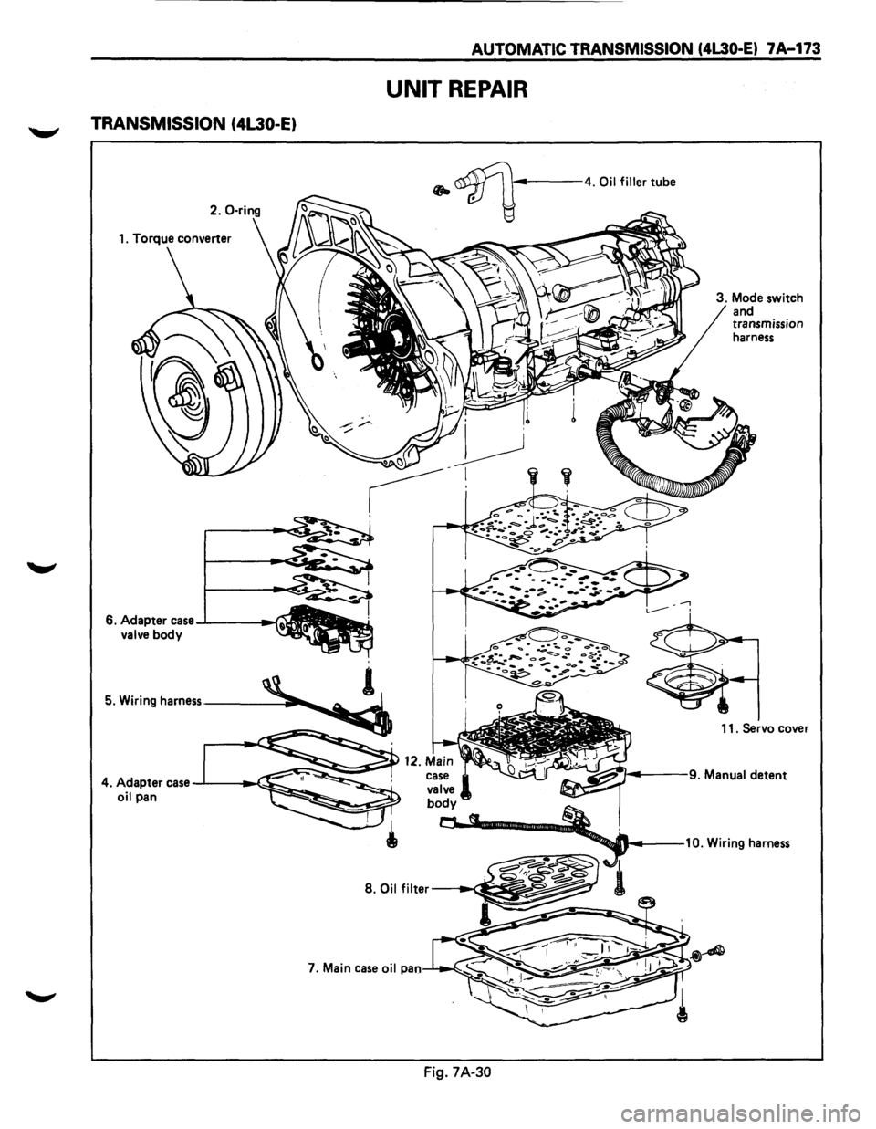
TRANSMISSION (4L30-E)
6. Adapter case -l------f valve body
AUTOMATIC TRANSMISSION (4L30-E) 7 A-173
UNIT REPAIR
• ~-----4. Oil filler tube
3. Mode switch
and
transmission
harness
11. Servo cover
case
valve body
~ §,.::•·• ~~--... ---10. Wiring harness
---1 ..... ~ 1 S.Oilfilter -~
I
Fig. 7A-30
Page 1046 of 1928
7A-174 AUTOMATIC TRANSMISSION (4L30·E)
1•!•1 biSASSEMBLV
During the disassembly and reassembly of the
following components, perform the following:
• Wash each part thoroughly and blow air
through each oil passage and groove to
eliminate blockage.
• Seal rings, roll pins and gaskets should be
replaced
with new parts.
• When assembling the components, apply
DEXRON®-m Automatic Transmission Fluid
(ATF)
to each seal, rotating part and sliding
part.
• Do not dip those parts having a facing, such as
drive plate for clutch or brake, in the cleaner
when washing it with solvent.
Also, always wash
it with new ATF two or
three times after cleaning with solvent.
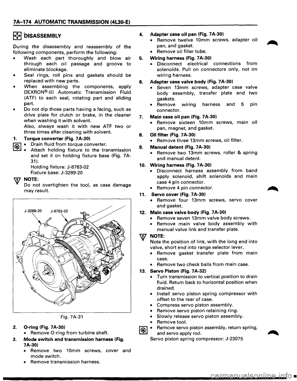
1. Torque converter (Fig. 7A-30)
l"i:\1 • Drain fluid from torque converter.
~ • Attach holding fixture to the transmission
and set it on holding fixture base (Fig. 7A-
31).
Holding fixture: J-8763-02
Fixture base: J-3289-20
w NOTE:
Do
not overtighten the tool, as case damage
may result.
Fig. 7A-31
2. 0-ring (Fig. 7 A-30)
•
Remove 0-ring from turbine shaft.
3. Mode switch and transmission harness (Fig.
7A-30)
•
Remove two 10mm screws, cover and
mode switch.
• Remove transmission harness.
4.
5.
6.
7.
8.
9.
10.
11.
12.
Adapter case oil pan (Fig. 7 A-30)
•
Remove twelve 10mm screws, adapter oil
pan, and gasket.
• Remove oil filler tube.
Wiring harness (Fig. 7 A-30)
•
Disconnect electrical connections from
solenoids. Pull on connectors only, not on
wiring harness.
Adapter case valve body (Fig. 7A-30)
• Seven
13mm screws, adapter case valve
body assembly, transfer plate and two
gaskets.
• Remove wmng harness and 5 pin
connector.
Main case oil pan (Fig. 7 A-30)
•
Remove sixteen 10mm screws, main oil
pan, magnet, and gasket.
Oil filter· (Fig. 7 A-30)
•
Remove three 13mm screws, oil filter.
Manual detent (Fig. 7 A-30)
•
Remove two 13mm screws, roller & spring
and manual detent.
Wiring harness (Fig. 7 A-30)
•
Disconnect harness assembly from band
apply solenoid, shift solenoids and main
case 4 pin connector.
• Remove 4 pin connector.
Servo cover (Fig. 7 A-30)
•
Remove four 13mm screws, servo cover
and
~1asket.
Main case valve body (Fig. 7 A-30)
•
Remove seven 13mm valve body screws.
• Remove main valve body assembly with
manual valve link and transfer plate.
NOTE: Note
thE! position of link, with the long end into
valve, short end into range selector lever.
• Remove gasket transfer plate from main
case.
• Remove two check balls from main case.
13.
Servo Piston (Fig. 7A-32)
• Turn transmission to vertical position to drain
fluid. Return back
to horizontal position when
drained.
• Install servo piston spring compressor with
offset to the rear of case.
• Compress servo piston assembly.
• Remove servo piston retaining ring.
• Slowly release servo piston assembly.
• Remove tool.
1®.1 • Remove servo piston assembly, return spring,
and servo apply rod.
Servo piston spring compressor: J-23075
•
Page 1059 of 1928
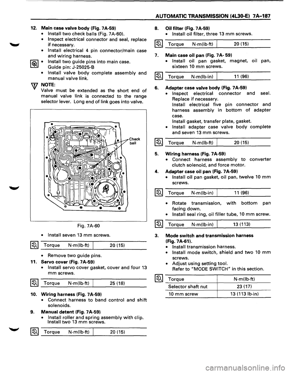
12. Main case valve body (fig. 7A-59)
• Install two check balls (Fig. 7A-60).
• Inspect electrical
connector and seal, replace
if necessary.
• Install electrical 4 pin connector/main case
and
wiring harness.
1®..1 • Install two guide pins into main case.
Guide pin:
J-25025-B
• Install valve
body complete assembly and
manual valve link.
W NOTE:
Valve must be extended as the short end of
manual valve link is connected to the range
selector lever. Long end of link goes into valve.
Fig. 7A-60
• Install
seven 13 mm screws.
~~~ Torque N·mOb·ft) I 20 (15)
• Remove two guide pins.
11.
Servo cover (fig. 7 A-59)
Check ball
• Install servo cover gasket, cover and four 13
mm screws.
~~~ Torque N·mOb·ft) I 25 ( 18)
10. Wiring harness (fig. 7A-59)
• Connect harness to band control and shift
solenoids.
9. Manual detent (fig. 7 A-59)
• Install roller and spring assembly with clip.
Install two 13 mm screws.
~~~ Torque N·mOb·ft) 20 (15)
AUTOMATIC TRANSMISSION (4L30-E) 7A-187
8. Oil filter (Fig. 7 A-59)
• Install oil filter, three 13 mm screws.
~~~ Torque N.m(lb·ft) I 20 (15)
7. Main
case oil pan (Fig. 7 A- 59)
• Install oil pan gasket, magnet, oil pan,
sixteen
10 mm screws.
~~~ Torque N·m(lb·in) I 11 (96)
6. Adapter case valve body (fig. 7 A-59)
• Inspect electrical connector and seal.
Replace
if necessary.
Install electrical five pin connector and
harness
assembly in bottom of adapter
case.
Install gasket, transfer plate, gasket.
• Install adapter case valve body complete
and seven 13 mm screws.
~~~ Torque N.m(lb.ft) I 20 (15)
5. Wiring harness (fig. 7A-59)
• Connect harness assembly to converter
clutch solenoid, and force motor.
4. Adapter case oil pan (fig. 7 A-59)
• Install oil pan gasket, oil pan, twelve 10 mm
screws.
~~~ Torque N·mOb·in) 11 (96)
• Rotate transmission, with bottom pan
facing
down.
• Install seal ring, oil filler tube, 10 mm screw.
~~~ Torque N·mOb·in) I 13 (113)
3. Mode switch and transmission harness
(Fig. 7A-61).
• Install transmission harness.
• Install mode switch, shield and two 10 mm
screws.
• Adjust using setting tool.
Refer to "MODE SWITCH" in this section.
~~~ Torque
Selector shaft nut
10 mm screw
N·mOb·ft)
23 (17)
13 (113 lb·in)
Page 1161 of 1928
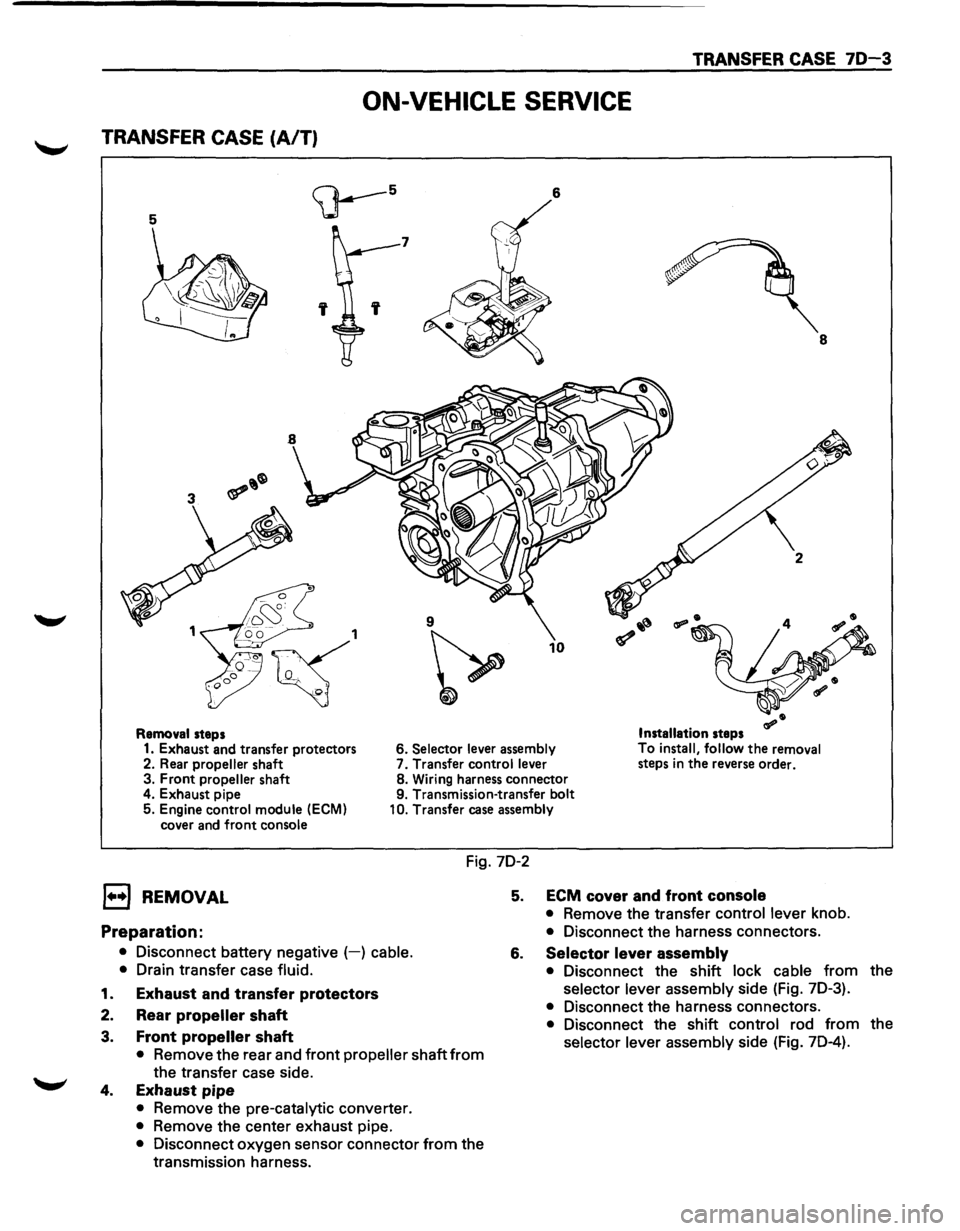
TRANSFER CASE 70-3
ON-VEHICLE SERVICE
TRANSFER CASE (A/T)
5
<;J---5 6
7
' 8
9
~
10
Removal steps Installation steps
1. Exhaust and transfer protectors 6. Selector lever
assembly To
install, follow the removal
steps in the reverse order.
2. Rear propeller shaft 7.
Transfer control lever
3. Front propeller shaft 8.
Wiring harness connector
4. Exhaust pipe 9. Transmission-transfer bolt
5. Engine control module
(ECM)
cover and front console 10.
Transfer case assembly
Fig. 7D-2
l••l REMOVAL
Preparation:
• Disconnect battery negative (-) cable.
•
Drain transfer case fluid.
1. Exhaust and transfer protectors
2. Rear propeller shaft
3. Front propeller shaft
• Remove the rear and front propeller shaft from
the transfer case side.
4. Exhaust pipe
• Remove the pre-catalytic converter.
• Remove the center exhaust pipe.
• Disconnect oxygen sensor connector from the
transmission harness.
5. ECM cover and front console
• Remove the transfer control lever knob.
• Disconnect the harness connectors.
6. Selector lever assembly
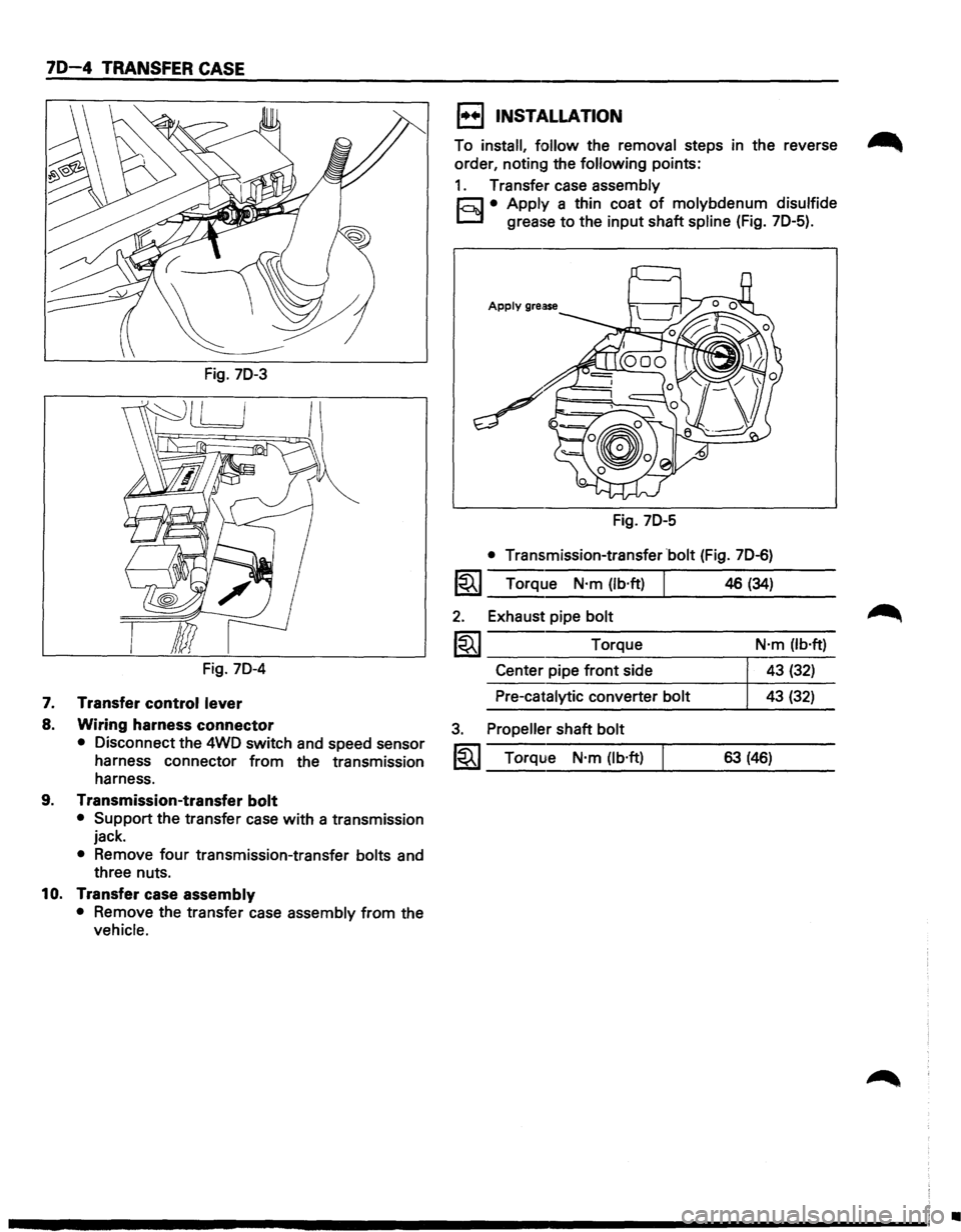
• Disconnect the shift lock cable from the
selector lever assembly side (Fig. 7D-3).
• Disconnect the harness connectors.
• Disconnect the shift control rod from the
selector lever assembly side (Fig. 7D-4).
Page 1162 of 1928
70-4 TRANSFER CASE
Fig. 70-3
Fig. 70-4
7. Transfer control lever
8. Wiring harness connector
• Disconnect the 4WD switch and speed sensor
harness connector from the transmission
harness.
9. Transmission-transfer bolt
• Support the transfer case with a transmission
jack.
• Remove four transmission-transfer bolts and
three nuts.
10. Transfer case assembly
• Remove the transfer case assembly from the
vehicle.
1••1 INSTALLATION
To install, follow the removal steps in the reverse ~
order, noting the following points:
1. Transfer case assembly
r;:;J • Apply a thin coat of molybdenum disulfide
D grease to the input shaft spline (Fig. 70-5).
Fig. 70-5
• Transmission-transfer bolt (Fig. 70-6)
1~1 Torque N·m (lb·ft)
2. Exhaust pipe bolt
1~1 Torque
Center pipe front side
Pre-catalytic converter bolt
3. Propeller shaft bolt
1~1 Torque N·m (lb·ft)
46 (34)
N·m (lb·ft)
43 (32)
43 (32)
63 (46)
•
Page 1191 of 1928

CHASSIS ELECTRICAL 8-1
·SECTION 8
CHASSIS ELECTRICAL
'\f CAUTION: .
When fasteners are removed, always reinstall them at the same location from which they were removed.
If a fastener needs to be replaced, use the correct part number fastener for that application. If the correct
part number fastener is not
available, a fastener of equal size and strength (or stronger) may be used.
Fasteners that are not reused, and those requiring thread
locking compound, will be called out. The correct
torque
values must be used when installing fasteners that require it. If the above conditions are not
followed, parts or system damage could result.
CONTENTS
General Information .................................... 8-2
Notes for Working on Electrical
Items .................................................... 8-2
Symbols and Abbreviations ................. 8-8
Symbols ............................................ 8-8
Abbreviations ................................... 8-9
Parts for Electrical Circuit ..................... 8-10
Wiring ............................................... 8-10
Fuse .................................................. 8-11
Fusible Link ....................................... 8-12
Circuit Breaker ................................... 8-12
Relay ................................................. 8-12
Relay Specifications and
Configurations ................................ 8-13
Diode ................................................. 8-14
Connector ......................................... 8-15
Reading the Circuit Diagram ................ 8-17
Main Data and Specifications .................... 8-19
Bulb Specifications ................................ 8-19
Fuse,
Fusible Link and
Circuit Breaker Location ..................... 8-21
Fuse
Block Circuit .................................. 8-22
Reference Table of Fuse, Fusible
Link and Circuit Breaker ..................... 8-23
Relay Location ....................................... 8-27
Diode Location .......................................
8-28
Grounding Point .................................... 8-29
Reference Table ................................ 8-29
Location ............................................ 8-31
Cable Harness Routing .......................... 8-34
System Repair .............................................. 8-38
Start and Charging ................................ 8-38
Engine Control Module
(ECM) ................................................... 8-47
Headlight and Fog Light ........................ 8-58
Front Side Marker Light, Parking Light,
Taillight, License Plate Light and
Illumination Light .............................. 8-76
Stoplight and Rear Defogger .............. 8-92
Turn Signal Light, Hazard
Warning
Light, Cornering Light,
Backup
Light and Horn ..................... 8-106
Dome Light, Luggage room Light,
Courtesy Light, Map Light,
Seat Belt Switch and
Warning Buzzer ................................. 8-128
Power Door Lock ................................. 8-142
Power
Window .................................... 8-156
Cruise
Control ...................................... 8-172
Anti-Lock Brake
System (ABS) ........... 8-178
Rear
Wheel Anti-Lock Brake
System (RWAL) ................................. 8-185
Transmission
Control Module
(TCM) ................................................. 8-192
A/T Shift Lock ...................................... 8-200
Windshield
Wiper/Washer and
Rear
Wiper/Washer .......................... 8-205
Headlight wiper /washer ..................... 8-232
Audio, Auto Antenna,
Cigarette
Lighter and digital clock ... 8-246
Power Door Mirror ............................... 8-254
Anti-theft System ................................ 8-270
Meter and Warning/Indicator Light ... 8-288
A/T Shift Indicator ............................... 8-336
Heater and
Air Conditioning ............... 8-340
Sun
Roof ............................................... 8-346
Power Seat ........................................... 8-360
Seat
Heater .......................................... 8-37 4
Supplemental Restraint
System (SRS) -AIR BAG ................... 8-382
Page 1195 of 1928
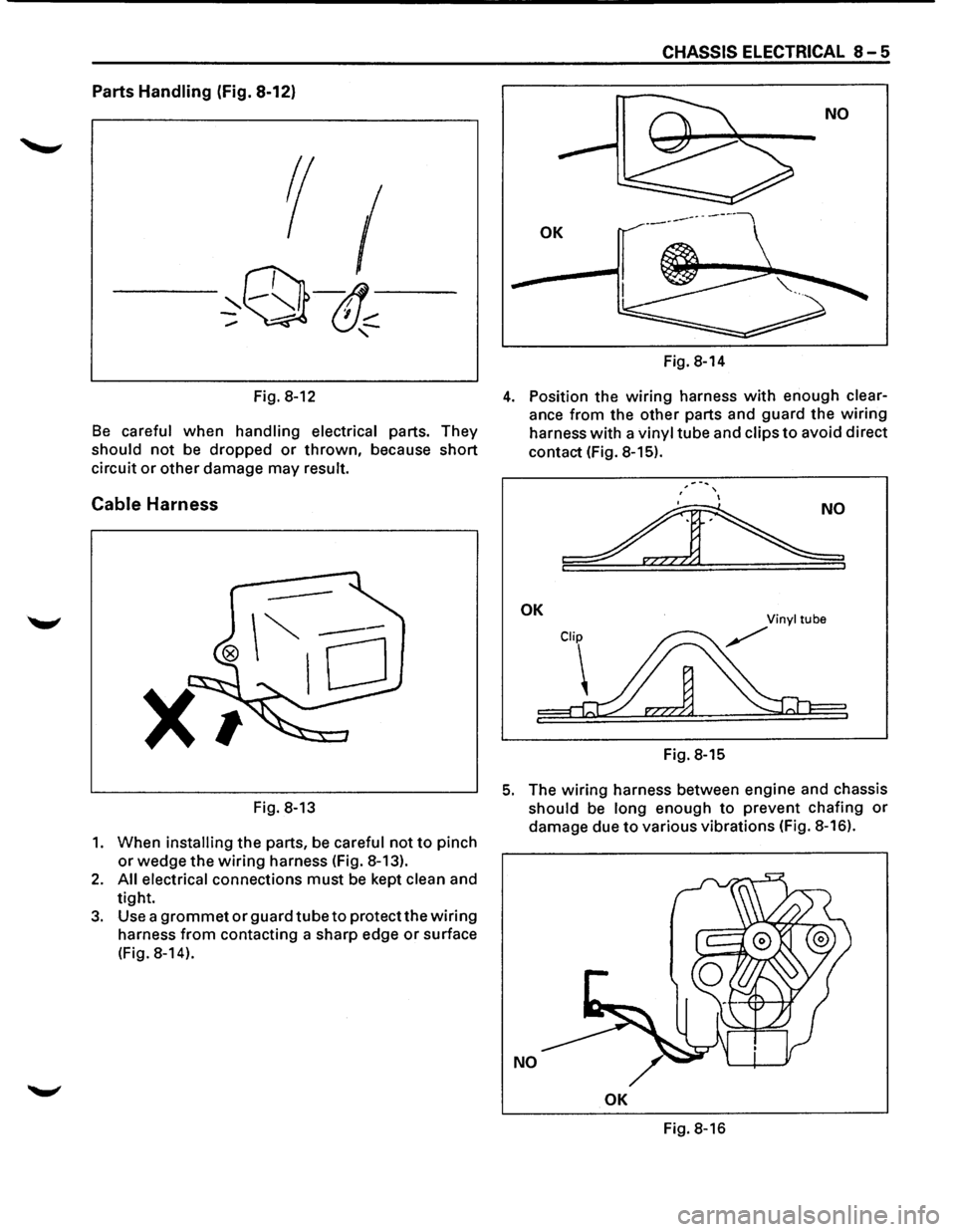
Parts Handling (Fig. 8-12)
Fig. 8-12
Be careful when handling electrical parts. They
should
not be dropped or thrown, because short
circuit
or other damage may result.
Cable Harness
--
Xt
Fig. 8-13
1. When installing the parts, be careful not to pinch
or wedge the wiring harness (Fig. 8-13).
2. All electrical connections must be kept clean and
tight.
3. Use a grommet orguardtubeto protect the wiring
harness from contacting a sharp edge or surface
(Fig.
8-14).
CHASSIS ELECTRICAL 8-5
Fig. 8-14
4. Position the wiring harness with enough clear
ance from the other parts and guard the wiring
harness with a vinyl tube and clips to avoid direct
contact (Fig.
8-15).
', '
~
OK
Fig. 8-15
5. The wiring harness between engine and chassis
should be long enough
to prevent chafing or
damage due to various vibrations (Fig. 8-16).
NO
OK
Fig. 8-16
Page 1198 of 1928
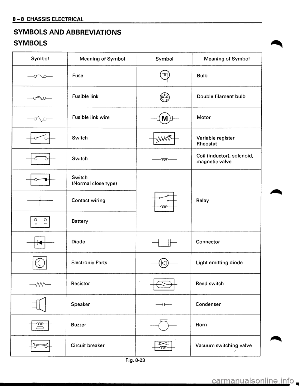
8-8 CHASSIS ELECTRICAL
SYMBOLS AND ABBREVIATIONS
SYMBOLS
Symbol Meaning of Symbol
~ Fuse
~ Fusible link
----if\p-Fusible link wire
~ Switch
~ Switch
-a-
Switch
(Normal close type)
j Contact wiring I
[I] -I
Battery
~
Diode
~
Electronic Parts
--Nt-Resistor
=Q] Speaker
1~1 Buzzer I
-EJ-Circuit breaker
I Symb•:>l Meaning of Symbol
~
Bulb
~ Double filament bulb
-r@[}-Motor
~j-Variable register
Rheostat
Coil (inductor), solenoid,
~-magnetic valve I
§
Relay
-or-Connector
----@-Light emitting diode
~8-
Reed switch
---11----Condenser
I -o-Horn
~t Vacuum switching valve I
Fig. 8-23
•
Page 1200 of 1928
8-10 CHASSIS ELECTRICAL
PARTS FOR ELECTRICAL CIRCUIT
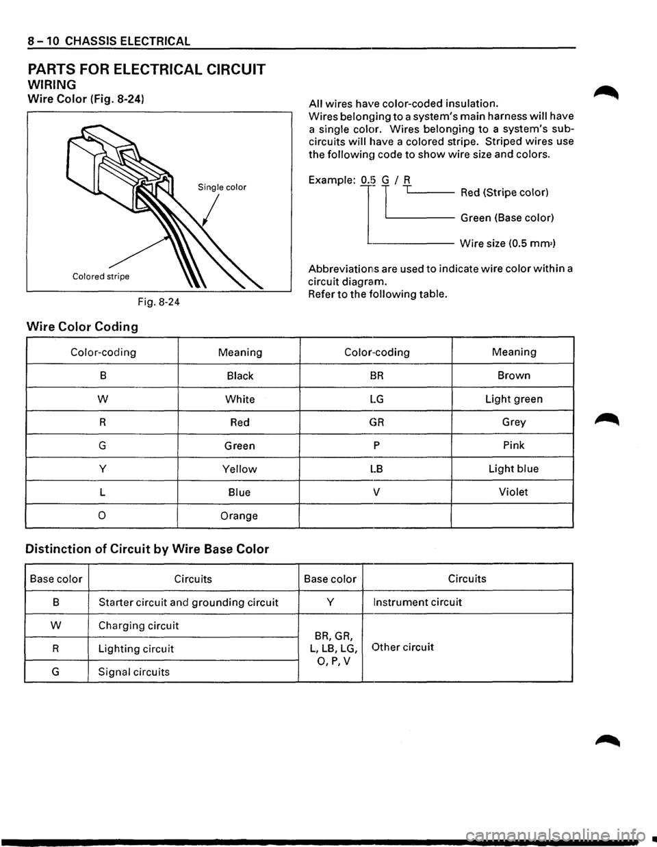
WIRING
Wire Color (Fig. 8-24)
Fig. 8-24
Wire Color Coding
Color-coding Meaning
B Black
w White
R
Red
G Green
y
Yellow
L Blue
0 Orange
Distinction of Circuit by Wire Base Color
Base color Circuits
B
Starter circuit and grounding circuit
w Charging circuit
R Lighting circuit
G Signal circuits
All wires have color-coded insulation.
Wires belon{)ing to a system's main harness will have
a
single color. Wires belonging to a system's sub
circuits will have a colored stripe. Striped wires use
the followinu code to show wire size and colors.
j '-----Red (Stripe color) Example:
1
0.!~ TL.-~-~---
Green (Base color)
------Wire size (0.5 mm•)
Abbreviations are used to indicate wire color within a
circuit diagram.
Refer to the following table.
Color-coding Meaning
BR Brown
LG Light green
GR Grey
p Pink
LB Light blue
v Violet
Base color Circuits
y
Instrument circuit
BR, GR,
L, LB, LG, Other circuit
O,P,V
Page 1201 of 1928
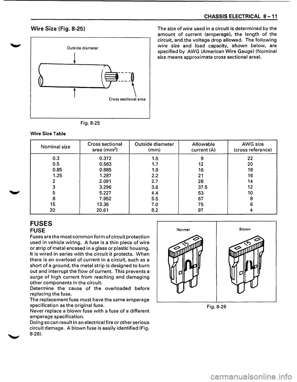
Wire Size (Fig. 8-25)
Outside diameter
Fig. 8-25
Wire Size Table
----,
Cross sectional area
CHASSIS ELECTRICAL 8 -11
The size of wire used in a circuit is determined by the
amount of current (amperage), the length of the
circuit, and the voltage drop allowed. The following
wire size and load capacity, shown below, are
specified
by AWG (American Wire Gauge) (Nominal
size means approximate cross sectional area).
Nominal size Cross sectional
Outside diameter Allowable AWG size
area
(mm2 ) (mm)
0.3
0.5
0.85
1.25
2
3
5 8
15
20
FUSES
FUSE
0.372
0.563
0.885
1.287
2.091
3.296
5.227
7.952
13.36
20.61
Fuses are the most common form of circuit protection
used in vehicle wiring. A fuse is a thin piece of wire
or strip of metal encased in a glass or plastic housing.
It is wired in series with the circuit it protects. When
there is an overload of current in a circuit, such as a
short of a ground, the metal strip is designed to burn
out and interrupt the flow of current. This prevents a
surge
of high current from reaching and damaging
other components in the circuit.
Determine the cause of the overloaded before
replacing the fuse.
The
replacement fuse must have the same amperage
specification as the original fuse.
Never replace a blown fuse with a fuse of a different
amperage specification.
Doing so can result in an electrical fire or other serious
circuit damage. A blown fuse is easily identified (Fig.
8-26). 1.5
1.7
1.9
2.2
2.7
3.6 4.4
5.5
7.0
8.2
current (A) (cross
reference)
9
22
12 20
16 18
21 16
28 14
37.5
12
53 10
67 8
75 6
97 4
Normal Blown
Fig.
8-26