wiring ISUZU TROOPER 1995 Owners Manual
[x] Cancel search | Manufacturer: ISUZU, Model Year: 1995, Model line: TROOPER, Model: ISUZU TROOPER 1995Pages: 1928
Page 1028 of 1928
7A-156 AUTOMATIC TRANSMISSION (4L30-E)
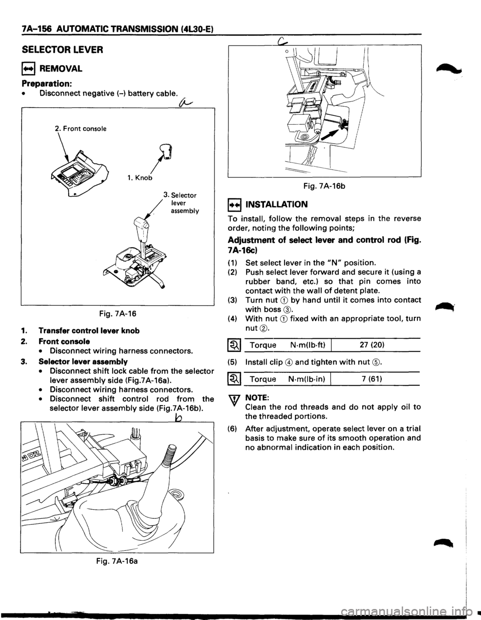
SELECTOR LEVER
B REMOVAL
Preparation:
• Disconnect negative (-) battery cable.
(}-
2. Front console
)3
1. Knob
Fig. 7A-16
1. Transfer control lever knob
2. Front console
3. Selector
lever
assembly
• Disconnect wiring harness connectors.
3. Selector lever assembly
• Disconnect shift lock cable from the selector
lever assembly
side (Fig.7A-16a).
• Disconnect wiring harness connectors.
• Disconnect shift control rod from the
selector lever assembly side (Fig.7A-16b).
Fig. 7A-16a Fig.
7A-16b
I••IINSTALLATION
To install, follow the removal steps in the reverse
order,
notin!~ the following points;
Adjustment of select lever and control rod (Fig.
7A-16c)
(1) Set sele1ct lever in the "N" position.
(2) Push select lever forward and secure it (using a
rubber band, etc.) so that pin comes into
contact with the wall of detent plate.
(3) Turn nut CD by hand until it comes into contact
with boss@.
(4) With nut CD fixed with an appropriate tool, turn
nut®.
~~~ Torque N·mOb·ft) I 27 (20)
(5) Install clip @ and tighten with nut @.
~~~ Torque N·m(lb·in) I 7 (61)
w NOTE:
Clean the rod threads and do not apply oil to
the threaded portions.
(6) After adjustment, operate select lever on a trial
basis to make sure of its smooth operation and
no
abnormal indication in each position.
.......
..._.
II
Page 1029 of 1928
Rubber band
Fig. 7A-16c
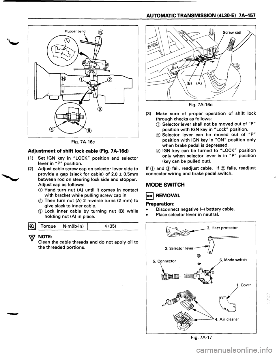
Adjustment of shift lock cable (Fig. 7A-16d)
(1) Set IGN key in "LOCK" position and selector
lever
in "P" position.
(2)
Adjust cable screw cap on selector lever side to
provide a gap (slack for cable) of 2.0 ± O.Smm
between rod on steering lock side and stopper.
Adjust cap as follows:
CD Hand turn nut (A) until it comes in contact
with bracket while pulling screw cap in
® Then turn nut (A) 2 reverse turns (2 mm) to
give slack to inner cable.
@ Lock inner cable by turning nut (8) while
holding nut (A) in place.
~~~ Torque N-m(lb-in) j 4 (35)
W NOTE:
Clean the cable threads and do not apply oil to
the threaded portions.
AUTOMATIC TRANSMISSION (4L30·E) 7A-157
Fig. 7A-16d
(3) Make sure of proper operation of shift lock
through checks as follows:
CD Selector lever shall not be moved out of "P"
position with IGN key in "Lock" position.
® Selector lever can be moved out of "P"
position with IGN key in "ON" position only
when brake pedal is depressed.
@ IGN key can be turned to "LOCK" position
only when selector lever is in "P" position
(key can be
pulled out).
If CD and @ fail, readjust cable. If ® fails, readjust
connector
wiring and brake pedal switch.
MODE SWITCH
1++1 REMOVAL
Preparation:
• Disconnect negative (-) battery cable.
• Place selector lever
in neutral.
~3. Heat protector
2. Selector lever
6. Mode switch
1. Cover
~
Fig. 7A-17
Page 1033 of 1928
1••1 REMOVAL
Preparation:
• Remove engine hood.
• Disconnect negative (-) battery cable.
1. Skid plate
2. Exhaust and transfer protectors
3. Rear propeller shaft
4. Front propeller shaft
5. Exhaust pipe
• Remove pre-catalytic converter, center pipe
and
front pipe.
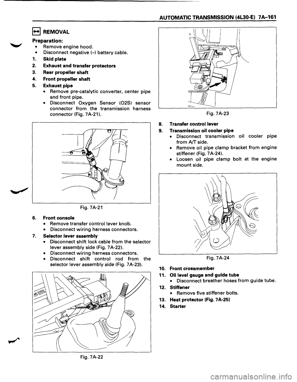
• Disconnect Oxygen Sensor (025) sensor
connector
from the transmission harness
connector (Fig.
7A-21).
Fig. 7A-21
6. Front console
• Remove transfer control lever knob.
• Disconnect wiring harness connectors.
7. Selector lever assembly
• Disconnect shift lock cable from the selector
lever assembly
side (Fig. 7 A-22).
• Disconnect wiring harness connectors.
• Disconnect shift control rod from the
selector lever assembly side (Fig. 7 A-23).
Fig. 7A-22
AUTOMATIC TRANSMISSION (4L30·E) 7A-161
Fig. 7A-23
8. Transfer control lever
9. Transmission oil cooler
pipe
• Disconnect transmission oil cooler pipe
from AfT side.
• Remove oil pipe clamp bracket from engine
stiffener (Fig.
7 A-24).
• Loosen oil pipe clamp bolt at the engine
mount side.
Fig.
7A-24
10. Front crossmember
11.
Oil level gauge and guide tube
• Disconnect breather hoses from guide tube.
12.
Stiffener
• Remove five stiffener bolts.
13. Heat protector (Fig. 7A-25}
14.
Starter
Page 1036 of 1928
7A-164 AUTOMATIC TRANSMISSION (4L30-E)
20. Third crossmember
~~~ Torque N·m(lb.ft) 50 (37)
19. Rear mount nut
~~~ Torque N·mOb·ft) 41 (30)
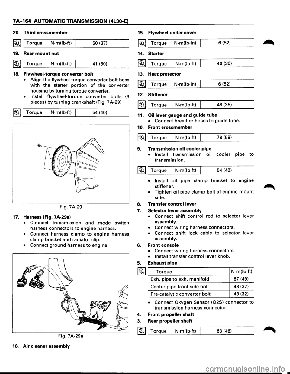
18. Flywheel-torque converter bolt
• Align
the flywheel-torque converter bolt boss
with the starter portion of the converter
housing
by turning torque converter.
• Install flywheel-torque converter bolts (3
pieces) by turning crankshaft (Fig. 7 A-29)
~~~ Torque N·mOb·ft) 54 (40)
Fig. 7A-29
17. Harness (fig. 7A-29a)
• Connect transmission and mode switch
harness connectors to engine harness.
• Connect harness clamp to engine harness
clamp bracket and radiator clip.
•
Connect ground harness to engine.
Fig. 7A-29a
16. Air
cleaner assembly
15. Flywheel under cover
~~~ TorqUte N·mOb·in)
14. Starter
~~~ Torqu,e N·m(lb·ft)
13. Heat protector
~~~ Torqu'e N·m(lb·in)
12. Stiffener
N·m(lb·ft)
11. Oil lever gauge and guide tube 6
(52)
40 (30)
6 (52)
48 (35)
• Connect breather hoses to guide tube.
10. Front crossmember
~~~ Torque N·m(lb·ft) I 78 (58)
9. Transmission oil cooler pipe
• Install transmission oil cooler pipe to
transmission.
~~~ Torqwe N·m(lb·ft) I 54 (40)
•
lnsta1ll oil pipe clamp bracket to engine
stiffener. .~
• Tighten oil pipe clamp bolt at engine mount
side.
8. Transfer control lever
7. Selector lever assembly
•
Connect shift control rod to selector lever
assembly.
•
Connect wiring harness connectors.
• Connect shift lock cable to selector lever
assembly.
6. Front cc>nsole
• Connect wiring harness connectors.
• Install transfer control lever knob.
5. Exhaust pipe
I~I ___ T_o_r_q~_ue __________________ 4-N_·_m_(l_b_·ft __ )
Exh. pipe
to exh. manifold 67 (49)
Center pipe
front side bolt 43 (32)
Pre-catalytic converter bolt 43 (32)
• Connect Oxygen Sensor (025) connector to
transmission harness connector.
4. Front propeller shaft
3. Rear propeller shaft
~~~ Torqwe N·mOb·ft) 63 (46)
Page 1037 of 1928
2. Exhaust and transfer protectors
~~~ Torque N-m(lb.ft) 37 (27)
1. Skid plate
• Connect negative (-) battery cable.
• Install
engine hood.
• Adjust shift lock cable.
Refer to "Selector lever" in this section.
SOLENOID VALVE
(MAIN CASE VALVE BODY)
l••l REMOVAL
Preparation:
• Disconnect negative {-) battery cable.
•
Remove exhaust protector and exhaust pipe.
1. Main case oil pan
• Remove sixteen 10 mm screws, main case
oil pan, magnet, and gasket.
• Drain fluid.
Refer to "CHANGING TRANSMISSION
FLUID".
2. Oil filter
• Remove three 13 mm screws, oil filter.
3. Wiring harness
• Disconnect wiring harness from band control
solenoid,
shift solenoids and main case 4 pin
connector.
Pull only on connectors, not on
wiring harness.
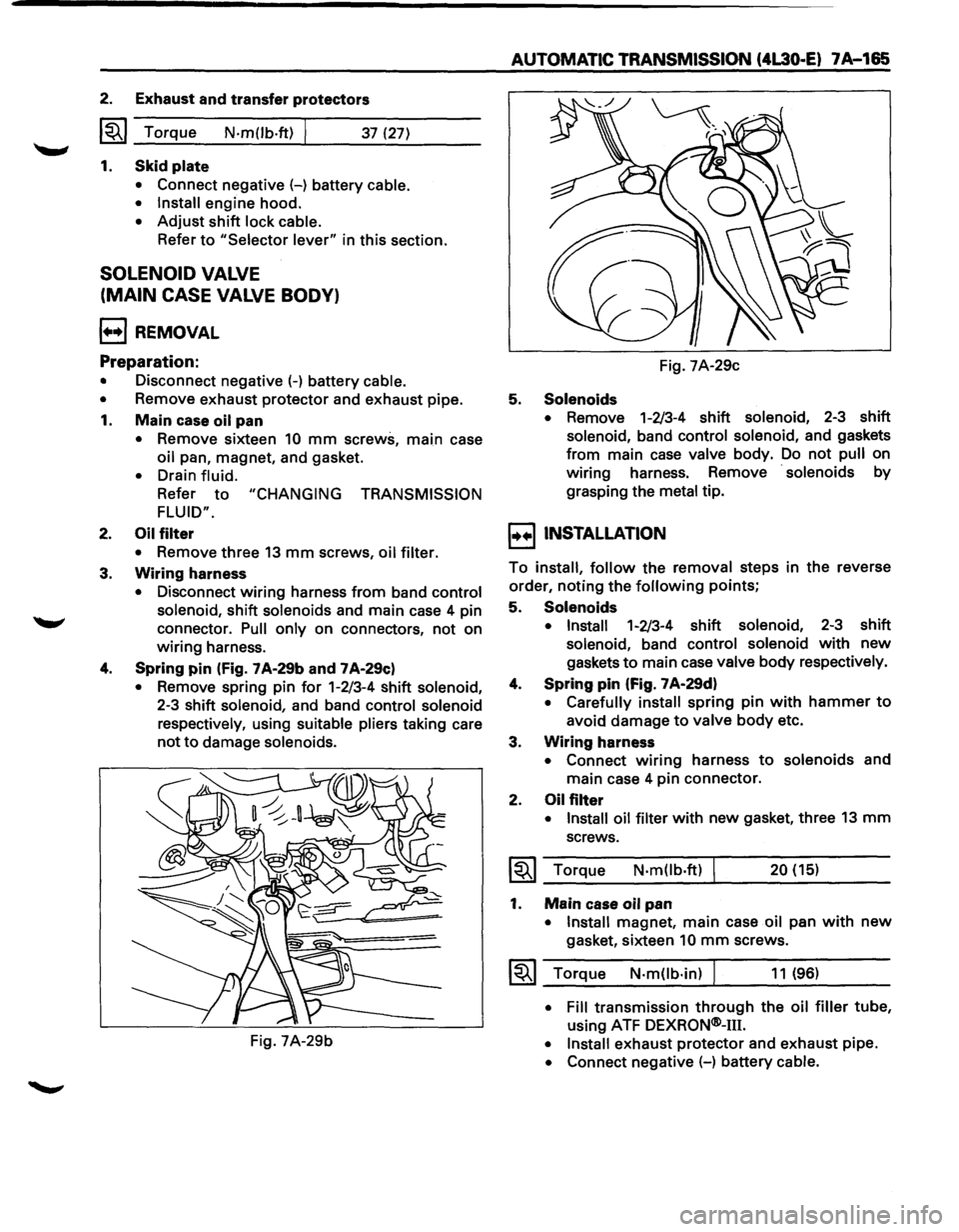
4. Spring pin (Fig. 7 A-29b and 7 A-29c)
• Remove spring pin for 1-2/3-4 shift solenoid,
2-3 shift solenoid, and band control solenoid
respectively,
using suitable pliers taking care
not to damage solenoids.
Fig. 7A-29b
AUTOMATIC TRANSMISSION (4L30 .. E) 7A-165
Fig. 7A-29c
5. Solenoids
• Remove 1-2/3-4 shift solenoid, 2-3 shift
solenoid, band control solenoid, and gaskets
from main case valve body. Do not pull on
wiring harness. Remove
· solenoids by
grasping the
metal tip.
I••! INSTALLATION
To install, follow the removal steps in the reverse
order,
noting the following points;
5. Solenoids
• Install 1-2/3-4 shift solenoid, 2-3 shift
solenoid, band control solenoid with new
gaskets to main case valve body respectively.
4. Spring pin (Fig. 7 A·29d)
• Carefully install spring pin with hammer to
avoid damage to valve body etc.
3. Wiring harness
• Connect wiring harness to solenoids and
main case 4 pin connector.
2. Oil filter
• Install oil filter with new gasket, three 13 mm
screws.
~~~ Torque N·m(lb.ft) 20 (15)
1. Main case oil pan
•
Install magnet, main case oil pan with new
gasket, sixteen 10 mm screws.
1~1 Torque N·m(lb·in) J 11 (96)
• Fill transmission through the oil filler tube,
using ATF DEXRQN®-m.
• Install exhaust protector and exhaust pipe.
• Connect negative (-) battery cable.
Page 1038 of 1928
7A-166 AUTOMATIC TRANSMISSION (4l30-E)
Fig. 7A-29d
SOLENOID VALVE
(ADAPTER CASE VALVE BODY)
l++l REMOVAL
Preparation:
• Disconnect negative(-) battery cable.
• Remove exhaust protector and exhaust pipe.
• Drain fluid.
• Refer to "CHANGING TRANSMISSION FLUID".
1. Adapter case oil pan
• Remove twelve 10 mm screws, adapter case
oil pan, and gasket.
NOTE:
Oil pan still contains transmission fluid. Place a
large
drain container under the oil pan.
Drain
the fluid carefully.
2. Wiring harness
• Disconnect wiring harness from force motor
solenoid, converter clutch solenoid and 5
pin
connector of adapter case. Pull only on
connectors,
not on wiring harness.
Fig. 7A-29e Fig.
7A-29f
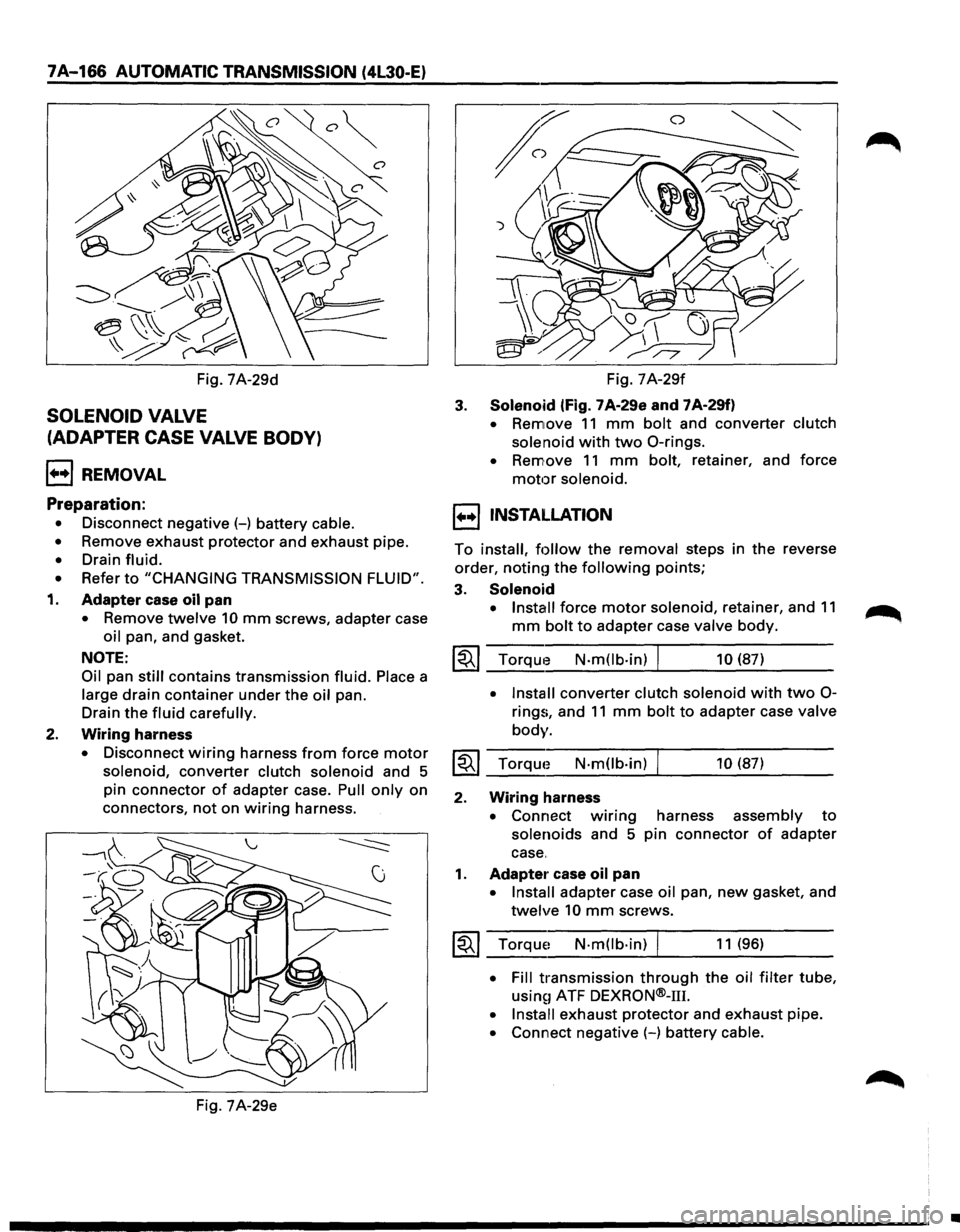
3. Solenoid (fig. 7 A-29e and 7 A-29f)
• Remove 11 mm bolt and converter clutch
solenoid
with two 0-rings.
• Remove 11 mm bolt, retainer, and force
motor solenoid.
1••1 INSTALLATION
To install, follow the removal steps in the reverse
order,
noting the following points;
3. Solenoid
• Install force motor solenoid, retainer, and 11
mm bolt to adapter case valve body.
~~~ Torque N-m(lb-in) I 10 (87)
• Install converter clutch solenoid with two 0-
rings, and 11 mm bolt to adapter case valve
body.
~~~ Torque N-mOb·in) 10 (87)
2. Wiring harness
• Connect w1nng harness assembly to
solenoids and 5 pin connector of adapter
case.
1. Adapter case oil pan
• Install adapter case oil pan, new gasket, and
twelve 10 mm screws.
~~~ Torque~ N·mOb·in) I 11 (96)
• Fill transmission through the oil filter tube,
usin~1 ATF DEXRON®-111.
• Install exhaust protector and exhaust pipe.
• Connect negative (-) battery cable.
•
Page 1039 of 1928
VALVE BODY ASSEMBLY (MAIN CASE)
1••1 REMOVAL
Preparation:
• Disconnect negative (-) battery cable.
• Remove exhaust protector and exhaust pipe.
1. Main case oil pan
• Remove sixteen 10 mm screws, main case
oil pan,
magnet and gasket.
• Drain fluid.
Refer
to "CHANGING TRANSMISSION
FLUID".
2. Oil filter
•
Remove three 13 mm screws, oil filter.
3. Manual detent
• Remove two 13 mm screws, roller and
spring assembly.
4. Wiring harness
• Disconnect wiring harness from band control
solenoid, shift solenoids and main
case 4 pin
connector.
Pull only on connectors, not on
wiring harness.
5.
Servo cover
• Remove four 13 mm screws, servo cover
and gasket.
6. Main case valve body
• Remove seven 13 mm valve body screws.
• Remove main valve body assembly with
manual valve link and transfer plate.
NOTE:
Note the position of link, with the long end into
valve, short end into range selector lever.
• Remove transfer plate gasket from main
case.
• Remove two check balls from main case.
I••IINSTALLATION
To install, follow the removal steps in the reverse
order,
noting the following points;
6. Main
case valve body
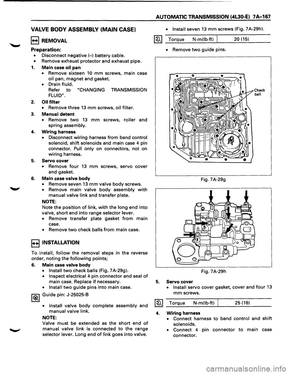
• Install two check balls (Fig. 7 A-29g).
• Inspect electrical 4 pin connector and seal of
main case. Replace if necessary.
• Install two guide pins into main case.
1®.1 Guide pin: J-25025-B
• Install
valve body complete assembly and
manual valve link.
NOTE:
Valve must be extended as the short end of
manual valve link is connected to the range
selector lever. Long end
of link goes into valve.
AUTOMATIC TRANSMISSION (4L30-E) 7A-167
• Install seven 13 mm screws (Fig. 7A-29h).
~~~ Torque N·m(lb·ft) I 20 (15)
5.
4.
• Remove two guide pins.
Fig. 7A-29g
Fig. 7A-29h
Servo cover
Check ball
• Install servo cover gasket, cover and four 13
mm screws.
Torque
N·mOb·ft) I 25 (18)
Wiring harness
• Connect harness to band control and shift
solenoids.
• Connect 4 pin connector to main case
connector.
Page 1040 of 1928
7A-168 AUTOMATIC TRANSMISSION (4L30-E)
3. Manual detent
• Install roller and spring assembly.
• Install
two 13 mm screws.
~~~ Torque N·m(lb.ft) I 20 (15)
2. Oil filter
• Install oil filter and three 13 mm screws.
~~~ Torque N-m(lb.ft) I 20 (15)
1. Main case oil pan
• Install oil pan gasket, magnet, oil pan and
sixteen
10 mm screws.
~~~ Torque N·m(lb-in) I 11 (96)
• Fill transmission through the oil filler tube,
using ATF
DEXRON®-111.
• Install exhaust pipe and exhaust protector.
• Connect negative (-) battery cable.
VALVE BODY ASSEMBLY (ADAPTER CASE)
1++1 REMOVAL
Preparation:
• Disconnect negative (-) battery cable.
•
Remove exhaust protector and exhaust pipe.
• Drain fluid.
•
Refer to "CHANGING TRANSMISSION FLUID".
1. Adapter case oil pan
• Remove twelve 10 mm screws, adapter case
oil pan and gasket.
NOTE:
Oil pan still contains transmission fluid. Place a
large drain container under the oil pan.
Drain the
fluid carefully.
2. Wiring harness
• Disc;:mnect wiring harness from force motor
solenoid, converter clutch solenoid and 5
pin
connector of adapter case. Pull only on
connectors,
not on wiring harness.
• Remove wiring harness.
3. Adapter case valve body
• Seve~n 13 mm screws, adapter case valve
body assembly, transfer plate and two
gaskets.
1++1 INSTALLATION
To install, follow the removal steps in the reverse
order,
notin~r the following points;
3. Adapter case valve body
• Inspect electrical 5 pin connector and seal of
adapter case. Replace if necessary.
• Install wiring harness assembly in bottom
of adapter case.
• Install gasket, transfer plate and gasket.
• Install adapter case valve body complete
and seven 13 mm screws.
~~~ Torque1 N·mOb·ft) 20 (15)
2. Wiring harness
• Connect harness assembly to converter
clutch solenoid and force motor.
1. Adapter case oil pan
• Instal!! oil pan gasket, oil pan and twelve 10
mm screws.
~~~ Torque N-m(lb-in) I 11 (96)
• Fill transmission through the oil filter tube,
using1 ATF DEXRON®-m.
• Install exhaust pipe and exhaust protector. ~
• Connect negative (-) battery cable.
•
Page 1041 of 1928
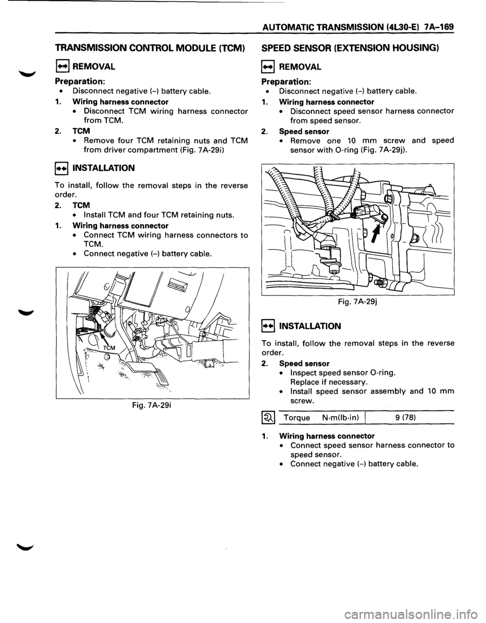
TRANSMISSION CONTROL MODULE (TCM)
1+•1 REMOVAL
Preparation:
• Disconnect negative (-) battery cable.
1. Wiring harness connector
• Disconnect TCM wiring harness connector
from TCM.
2. TCM
• Remove four TCM retaining nuts and TCM
from driver compartment (Fig. 7A-29i)
!•+I INSTALLATION
To install, follow the removal steps in the reverse
order.
2. TCM
• Install TCM and four TCM retaining nuts.
1. Wiring harness connector
• Connect TCM wiring harness connectors to
TCM.
• Connect negative (-) battery cable.
Fig. 7A-29i
AUTOMATIC TRANSMISSION (4L30-El 7A-169
SPEED SENSOR (EXTENSION HOUSING)
1+•1 REMOVAL
Preparation:
• Disconnect negative (-) battery cable.
1. Wiring harness connector
• Disconnect speed sensor harness connector
from speed sensor.
2. Speed sensor
• Remove one 10 mm screw and speed
sensor
with 0-ring (Fig. 7 A-29j).
Fig. 7A-29j
I•+IINSTALLATION
To install, follow the removal steps in the reverse
order.
2. Speed sensor
• Inspect speed sensor 0-ring.
Replace if necessary.
• Install speed sensor assembly and 10 mm
screw.
~~~ Torque N·mOb·in) 9 (78)
1. Wiring harness connector
• Connect speed sensor harness connector to
speed sensor.
• Connect negative (-) battery cable.
Page 1042 of 1928
7 A-170 AUTOMATIC TRANSMISSION (4L30-E)
TRANSMISSION OIL TEMPERATURE
SENSOR (ADAPTER CASE)
1•+1 REMOVAL
Preparation:
• Disconnect negative (-) battery cable.
•
Remove exhaust protector and exhaust pipe.
• Drain fluid.
•
Refer to "CHANGING TRANSMISSION FLUID".
1. Adapter case oil pan
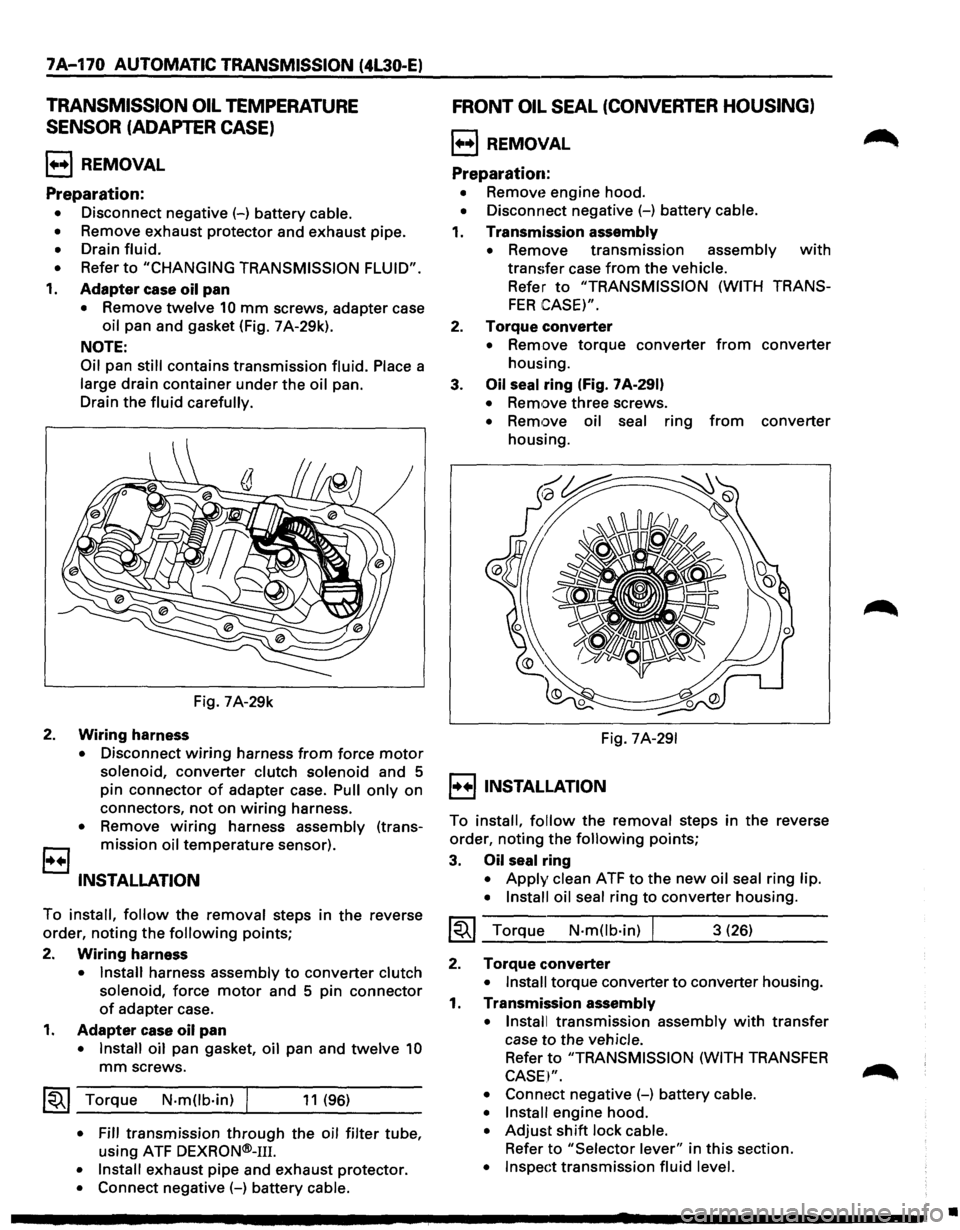
• Remove twelve 10 mm screws, adapter case
oil pan and gasket (Fig. 7 A-29k).
NOTE:
Oil
pan still contains transmission fluid. Place a
large drain container under the oil pan.
Drain the
fluid carefully.
Fig. 7A-29k
2. Wiring harness
• Disconnect wiring harness from force motor
solenoid, converter clutch solenoid and 5
pin connector
of adapter case. Pull only on
connectors,
not on wiring harness.
• Remove wiring harness assembly (trans
B mission oil temperature sensor).
INSTALLATION
To install, follow the removal steps in the reverse
order, noting the
following points;
2.
Wiring harness
• Install harness assembly to converter clutch
solenoid,
force motor and 5 pin connector
of adapter case.
1. Adapter case oil pan
• Install oil pan gasket, oil pan and twelve 10
mm screws.
~~~ Torque N·mOb·in) I 11 (96)
• Fill transmission through the oil filter tube,
using ATF
DEXRON®-111.
• Install exhaust pipe and exhaust protector.
• Connect negative (-) battery cable.
FRONT OIL SEAL (CONVERTER HOUSING)
l++l REMOVAL
Preparation:
• Removt~ engine hood.
• Disconnect negative (-) battery cable.
1. Transmission assembly
•
Remove transmission assembly with
transfer case from the vehicle.
Refer to "TRANSMISSION (WITH TRANS
FER CASE)".
2. Torque converter
• Remove torque converter from converter
housing.
3.
Oil seal ring (Fig. 7 A-291)
• Remove three screws.
• Remove oil seal ring from converter
housing.
Fig.
7A-291
I++IINSTALLATION
To install, follow the removal steps in the reverse
order, noting the
following points;
3. Oil seal ring
• Apply clean ATF to the new oil seal ring lip.
• Install oil seal
ring to converter housing.
~~~ Torque N·mOb·in) I 3 (26)
2. Torque converter
• Install torque converter to converter housing.
1. Transmission assembly
• Install
transmission assembly with transfer
case
to the vehicle.
Refer to "TRANSMISSION (WITH TRANSFER
CASE I".
• Connoct negative (-) battery cable.
• Install
engine hood.
• Adjust shift lock cable.
Refer to "Selector lever" in this section.
• Inspect transmission fluid level.
•