check oil ISUZU TROOPER 1995 Workshop Manual
[x] Cancel search | Manufacturer: ISUZU, Model Year: 1995, Model line: TROOPER, Model: ISUZU TROOPER 1995Pages: 1928
Page 1148 of 1928
7C 14 CLUTCH
1••1 REMOVAL
1. Pin and jaw joint pin
2. Pedal assembly and switch
3. Oil line pipe
4. Slave cylinder assembly and heat protector
5. Master cylinder assembly
6. Damper cylinder assembly
ll.•l INSPECTION AND REPAIR
Make necessary adjustments, repairs, and part
replacement
if wear, damage or other problems are
discovered during inspection.
1••1 INSTALLATION
To install, follow the removal steps in the reverse
order, noting the
following points:
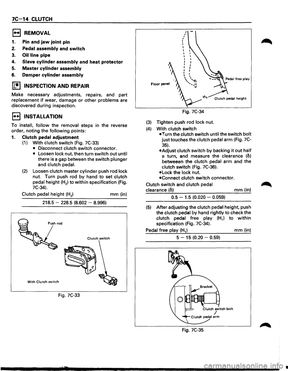
1. Clutch pedal adjustment
(1) With clutch switch (Fig. 7C-33)
• Disconnect clutch switch connector.
• Loosen lock nut, then turn switch out until
there is a gap between the switch plunger
and
clutch pedal.
(2) Loosen clutch master cylinder push rod lock
nut. Turn push rod by hand to set clutch
pedal height (H2) to
within specification (Fig.
7C-34).
Clutch
pedal height (H2 ) mm (in)
218.5
-228.5 (8.602 -8.996)
Clutch switch
With Clutch switch
Fig. 7C-33
Floor panel
Fig. 7C-34
(3) Tighten push rod lock nut.
(4) With clutch switch
Clutch pedal height
•Turn the clutch switch until the switch bolt
justtouches the clutch pedal arm (Fig. 7C
:~5).
•Adjust clutch switch by backing it out half
a
turn, and measure the clearance (o)
betweeen the clutch pedal arm and the
c:lutch switch (Fig. 7C-36).
•Lock the lock nut.
•Connect clutch switch connector.
Clutch switch and clutch
pedal
clearance
(o) mm (in)
0.5 -1.5 (0.020 -0.059)
(5) After adjusting the clutch pedal height, push
the clutch pedal
by hand rightly to check the
clutch pedal free play (H1) to within
specification (Fig. 7C-34).
Pedal free play (H1) mm (in)
5 -
15 (0.20 -0.59)
Fig. 7C-35
•
Page 1179 of 1928
GEARS
• Inspect all gear teeth for signs of excessive wear
'--" or damage and check all gear splines for burrs,
nicks,
wear or damage. Remove minor nicks or
scratches on an oil stone. Replace any part
exhibiting excessive wear or damage.
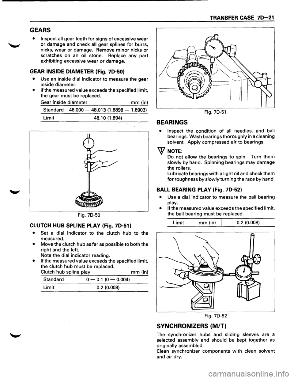
GEAR INSIDE DIAMETER (Fig. 7D-50}
• Use an inside dial indicator to measure the gear
inside diameter.
• If the measured value exceeds the specified limit,
the gear
must be replaced.
Gear inside diameter
mm (in)
Standard
48.000 -48.013 (1.8898 -1.8903)
Limit 48.1 0 (1.894)
Fig.
70-50
CLUTCH HUB SPLINE PLAY (Fig. 7D-51)
• Set a dial indicator to the clutch hub to the
measured.
• Move the clutch hub as far as possible to both the
right and the left.
Note the dial indicator reading.
• If the measured value exceeds the specified limit,
the clutch hub
must be replaced.
Clutch hub spline play
mm (in)
Standard
0 -0.1 (0 -0.004)
Limit 0.2 (0.008)
TRANSFER CASE 7D-21
I I
Fig. 70-51
BEARINGS
• Inspect the condition of all needles, and ball
bearings. Wash bearings thoroughly in a cleaning
solvent.
Apply compressed air to bearings.
W NOTE:
Do not allow the bearings to spin. Turn them
slowly by hand. Spinning bearings may damage
the
rollers.
Lubricate bearings with a light oil and check them
for roughness by slowly turning the race by hand.
BALL BEARING PLAY (Fig. 7D-52}
• Use a dial indicator to measure the ball bearing
play.
• If the measured value exceeds the specified limit,
the
ball bearing must be replaced.
Limit
mm (in) I 0.2 (0.008)
Fig. 70-52
SYNCHRONIZERS (MIT)
The synchronizer hubs and sliding sleeves are a
selected assembly and should be kept together
as
originally assembled.
Clean synchronizer components
with clean solvent
and air dry.
Page 1209 of 1928
CHASSIS ELECTRICAL 8-19
MAIN DATA AND SPECIFICATIONS
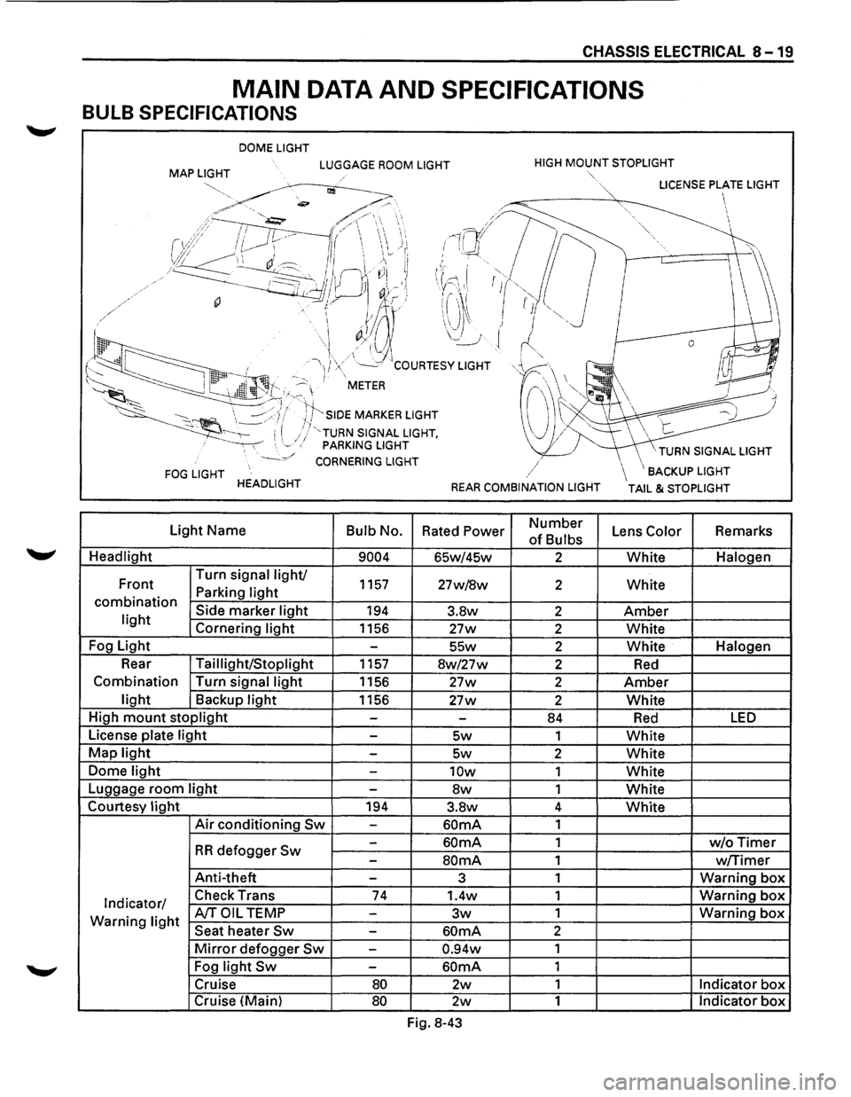
BULB SPECIFICATIONS
DOME LIGHT
MAP LIGHT LUGGAGE ROOM LIGHT HIGH MOUNT STOPLIGHT
FOG LIGHT HEADLIGHT
Light Name
Bulb No.
Headlight
9004
Front Turn
signal light/ 1157 Parking light combination Side marker light 194 light Cornering light 1156
Fog Light
-
Rear Taillight/Stoplight 1157
Combination Turn signal
light 1156
light Backup light 1156
High
mount stoplight -
License plate light -
Map light -
Dome light -
Luggage room light -
Courtesy light 194
Air conditioning Sw -
-
RR defogger Sw -
Anti-theft -
Indicator/ Check
Trans 74
Warning light A/TOIL TEMP -
Seat heater Sw -
Mirror defogger Sw -
Fog light Sw -
Cruise 80
Cruise (Main) 80
""·
,/
REAR COMBINATION LIGHT
Rated Power Number
of Bulbs
65w/45w 2
27w/8w 2
3.8w 2
27w 2
55w 2
8w/27w 2
27w 2
27w 2
-84
5w 1
5w 2
10w 1
8w 1
3.8w 4
60mA 1
60mA 1
SOmA 1
3 1
1.4w 1
3w 1
60mA 2
0.94w 1
60mA 1
2w 1
2w 1
Fig. 8-43
\BACKUP LIGHT
TAIL & STOPLIGHT
Lens Color Remarks
White Halogen
White
Amber
White
White Halogen
Red
Amber
White
Red LED
White
White
White
White
White
w/oTimer
w/Timer
Warning box
Warning box
Warning box
Indicator box
Indicator box
Page 1210 of 1928
8-20 CHASSIS ELECTRICAL
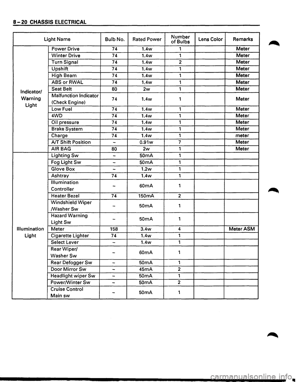
Light Name Bulb No. Rated Power Number Lens Color Remarks of Bulbs
Power Drive 74 1.4w 1
Meter
Winter Drive 74 1.4w
1 Meter
Turn Signal 74 1.4w 2 Meter
Upshift
74 1.4w 1 Meter
High Beam
74 1.4w 1 Meter
ABSorRWAL 74 1.4w 1 Meter
Indicator/ Seat Belt 80 2w 1 Meter
Warning Malfunction Indicator 74 1.4w
1 Meter
Light (Check
Engine)
Low Fuel 74 1.4w 1 Meter
4WD
74 1.4w 1 Meter
Oil pressure 74 1.4w 1 Meter
Brake System 74 1.4w 1 Meter
Charge 74 1.4w 1
meter
A/T Shift Position -0.91w 7 Meter
AIR BAG 80 2w 1 Meter
Lighting Sw -SOmA 1
Fog Light
Sw -SOmA 1
Glove Box -1.2w 1
Ashtray
74 1.4w 1
Illumination
60mA 1 -Controller
Heater Bezel 74 1SOmA 2
Windshield
Wiper SOmA 1 -/WasherSw
Hazard Warning SOmA 1 -Light Sw
Illumination Meter 158 3.4w 4 MeterASM
Light
Cigarette Lighter
74 1.4w
1
Select Lever -1.4w 1
Rear
Wiper/ 60mA 1 -WasherSw
Rear Defogger Sw -SOmA 1
Door
Mirror Sw -45mA 2
Headlight
wiper Sw -SOmA 1
Power/Winter
Sw -SOmA 2
Cruise Control
SOmA 1 -Main sw
II
Page 1214 of 1928
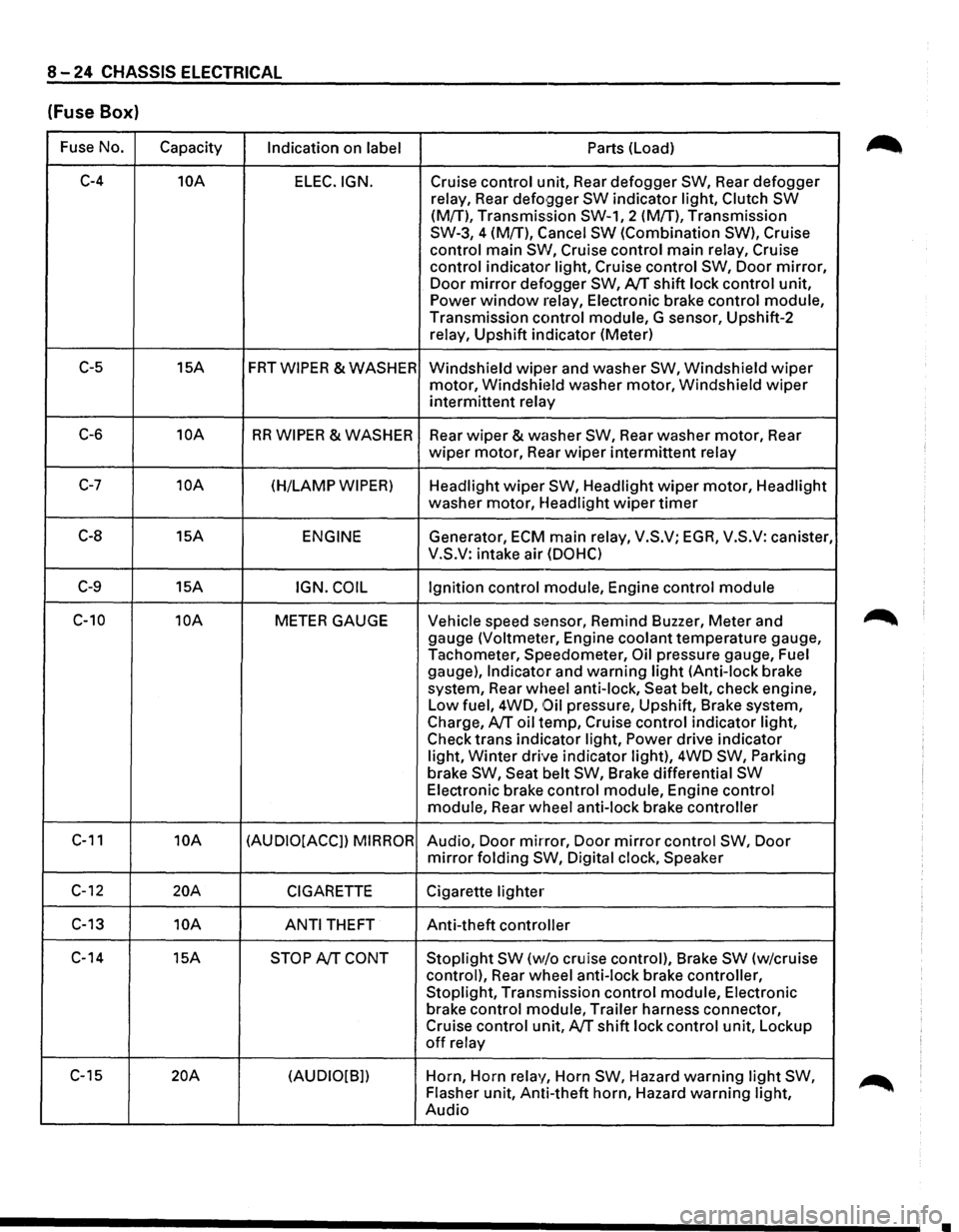
8-24 CHASSIS ELECTRICAL
(Fuse Box)
Fuse No.
Capacity Indication on label Parts (Load)
C-4 10A
ELEC.IGN. Cruise control unit, Rear defogger SW, Rear defogger
relay, Rear
defo9ger SW indicator light, Clutch SW
(M{T), Transmission SW-1, 2 (M!T), Transmission
SW-3, 4 (M{T), Cancel
SW (Combination SW), Cruise
control main
SW, Cruise control main relay, Cruise
control indicator light, Cruise control
SW, Door mirror,
Door mirror defogger SW, AfT shift lock control unit,
Power window relay, Electronic brake control module,
Transmission control module, G sensor, Upshift-2
relay, Upshift indicator (Meter)
C-5 15A FRTWIPER &WASHER
Windshield wipt~r and washer SW, Windshield wiper
motor, Windshit~ld washer motor, Windshield wiper
intermittent relay
C-6 10A RR WIPER & WASHER
Rear wiper & washer SW, Rear washer motor, Rear
wiper motor, Rear wiper intermittent relay
C-7 10A (H/LAMP WIPER) Headlight wiper SW, Headlight wiper motor, Headlight
washer motor, Headlight
wiper timer
C-8 15A ENGINE Generator, ECM main relay, V.S.V; EGA, V.S.V: canister,
V.S.V: intake air
(DOHC)
C-9 15A IGN. COIL Ignition control module, Engine control module
C-10 10A METER GAUGE Vehicle speed stmsor, Remind Buzzer, Meter and
gauge
(Voltmeter, Engine coolant temperature gauge,
Tachometer, Speedometer,
Oil pressure gauge, Fuel
gauge),
Indicator and warning light (Anti-lock brake
system, Rear wheel anti-lock, Seat belt, check engine,
Low fuel, 4WD,
Oil pressure, Upshift, Brake system,
Charge,
AfT oil temp, Cruise control indicator light,
Check trans indicator light,
Power drive indicator
light,
Winter drive indicator light), 4WD SW, Parking
brake SW, Seat belt SW, Brake differential SW
Electronic brake control module, Engine control
module, Rear wheel anti-lock brake controller
C-11 10A (AUDIO[ACCJ) MIRROR Audio, Door mirror, Door mirror control SW, Door
mirror folding SW, Digital clock, Speaker
C-12 20A CIGARETTE Cigarette lighter
C-13 10A
ANTI THEFT Anti-theft controller
C-14 15A
STOP AfT CONT Stoplight SW (w/o cruise control), Brake SW (w/cruise
control), Rear wheel anti-lock brake controller,
Stoplight, Transmission control module, Electronic
brake control module, Trailer harness connector,
Cruise control unit,
AfT shift lock control unit, Lockup
off relay
C-15
20A (AUDIO[B]) Horn,
Horn relay, Horn SW, Hazard warning light SW,
Flasher unit, Anti-theft horn, Hazard warning light,
Audio
•
Page 1260 of 1928
I ..
8 -70 CHASSIS ELECTRICAL
When placing a live inflator module on a bench
or other surface, always face the bag and trim
cover up, away from the surface. This is neces
sary so that a free space is provided to allow the
air bag to expand in the unlikely event of acci·
dental
deployment.
4. Steering wheel
• Refer to STEERING WHEEL REPLACEMENT in
Section 3F4.
5. Lighting switch (Combination switch)
• Disconnect the switch connector.
• Remove four screws.
• Remove the lighting switch together with SRS
coil assembly.
'\f CAUTION:
Do not remove SRS coil assembly from the com·
bination switch assembly.
E) INSTALLATION
To install, follow the removal steps in the reverse
order, noting the
following points.
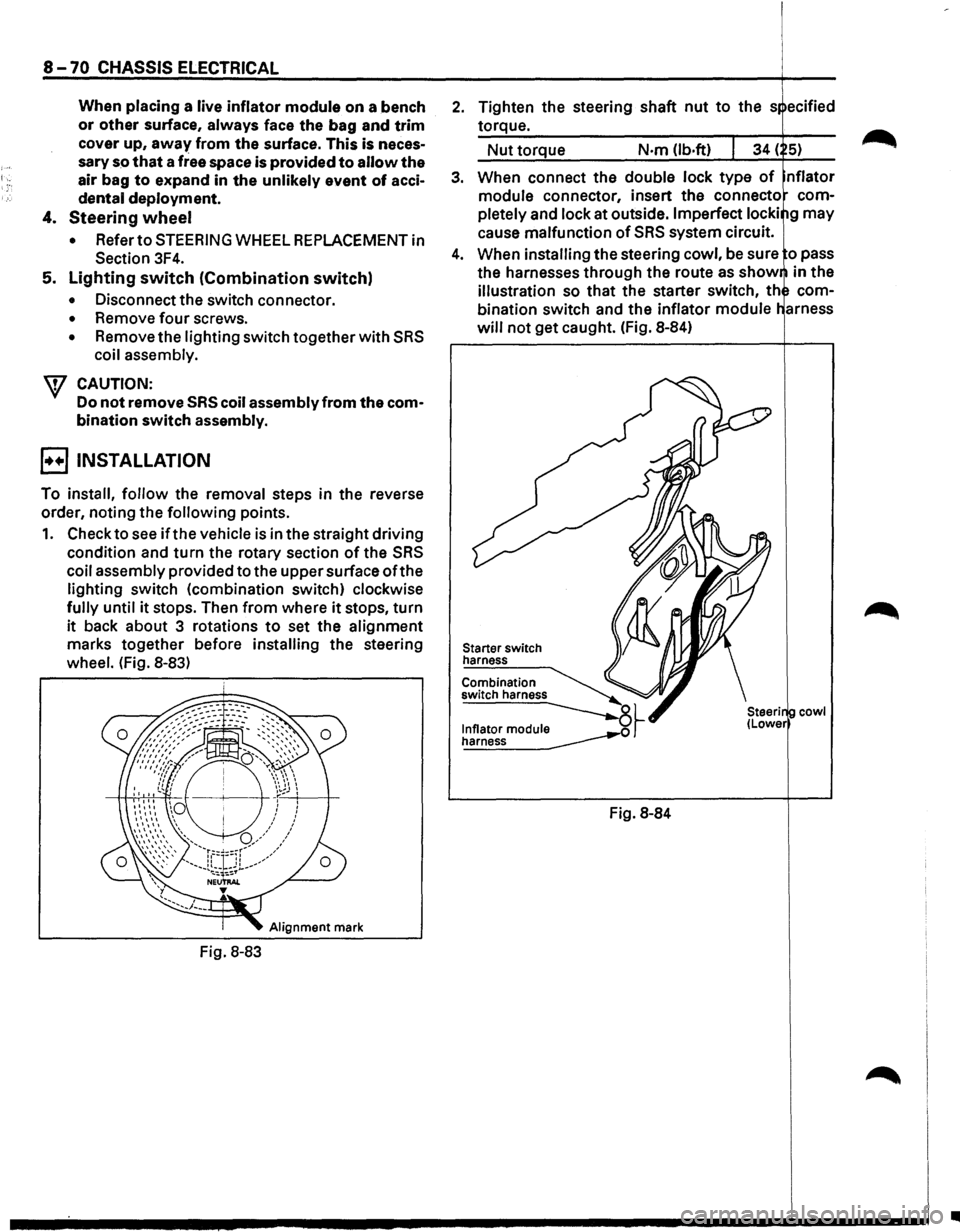
1. Check to see if the vehicle is in the straight driving
condition and turn the rotary section of the SRS
coil assembly provided to the upper surface ofthe
lighting switch (combination switch) clockwise
fully until it stops. Then from where it stops, turn
it back about 3 rotations to set the alignment
marks together before installing the steering
wheel. (Fig. 8-83)
Alignment mark
Fig. 8-83
2. Tighten the steering shaft nut to the s ecified
torque.
Nut torque N·m (lb.ft)
3. When connect the double lock type of nflator
module connector, insert the connecto com
pletely
and lock at outside. Imperfect locki g may
cause malfunction of SRS system circuit.
4. When installing the steering cowl, be sure o pass
the harnesses
through the route as show in the
illustration so that the starter switch, th com
bination switch and the inflator module
will not get caught. (Fig. 8-84)
Starter switch
harness
Combination
switch harness
~~ ~
Fig. 8-84
cowl
•
Page 1293 of 1928
![ISUZU TROOPER 1995 Workshop Manual REAR DEFOGGER SWITCH
(1!] INSPECTION
I~~ Check to see if there is any continuity between
the terminals
of the defogger switch. (Fig. 8-127)
Replace the switch, when the result
of inspecti](/img/61/57183/w960_57183-1292.png "ISUZU TROOPER 1995 Workshop Manual REAR DEFOGGER SWITCH
(1!] INSPECTION
I~~ Check to see if there is any continuity between
the terminals
of the defogger switch. (Fig. 8-127)
Replace the switch, when the result
of inspecti")
REAR DEFOGGER SWITCH
(1!] INSPECTION
I~~ Check to see if there is any continuity between
the terminals
of the defogger switch. (Fig. 8-127)
Replace the switch, when the result
of inspection
is found abnormal.
a [~~·~] ]]
r ~)
~0. s 1
4
ON o-r--0---
OFF o-~
Fig. 8-127
B REMOVAL (FIG. 8-128)
5. Rear defogger switch
Fig. 8-128
[ill
5 2 1 s
-o
~
4. Instrument panel
.cluster assembly
CHASSIS ELECTRICAL 8-103
Preparation: Disconnect the battery ground cable.
1.
Front console assembly
2. Lower cluster assembly
3. Instrument panel driver lower cover
4. Instrument panel cluster assembly
• Refer to FOG LIGHT SWITCH removal steps
in
this section.
5.
Rear defogger switch
• To remove the switch, pushing the lock from
the back side of the cluster assembly.
E) INSTALLATION
To install, follow the removal steps in the reverse
order, noting
the following point.
1. Push in the switch with your fingers until it locks
securely.
REAR DEFOGGER HEAT WIRES
w CAUTION:
• Heat wires are printed on the inner side of
the rear glass.
To clean, use a
soft cloth and wipe horizon
tally along the wires.
• Never use glass cleaner or equivalent.
~ INSPECTION
It~ I Measure the voltage of heat wire.
Repair the heat wire
when the result of inspection
is found abnormal.
'f CAUTION:
• When measuring voltage, wind a piece of
tin foil around the tip of the negative probe
and press
the foil against the wire with your
finger (Fig. 8-129).
1. Turn the starter switch on.
2. Turn the rear defogger switch on.
3. Measure the voltage between the three points
on
the heat wire and the(-) terminal with a voltmeter.
4. Check that the voltage becomes smaller from ®
to @to© (Fig. 8-130).
5. If there is a place where the voltage suddenly
changes
to OV, there is a OPEN CIRCUIT between
there and the
prior point.
Page 1382 of 1928
8-192 CHASSIS ELECTRICAL
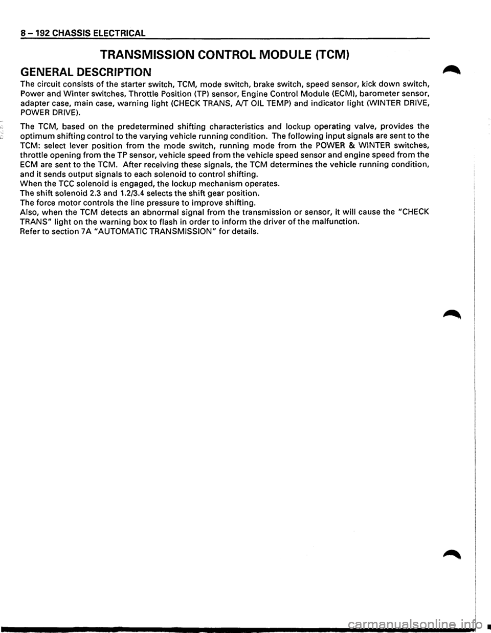
TRANSMISSION CONTROL MODULE (TCM)
GENERAL DESCRIPTION
The circuit consists of the starter switch, TCM, mode switch, brake switch, speed sensor, kick down switch,
Power and
Winter switches, Throttle Position (TP) sensor, Engine Control Module (ECM), barometer sensor,
adapter case, main case,
warning light (CHECK TRANS, NT OIL TEMP) and indicator light (WINTER DRIVE,
POWER DRIVE).
The TCM, based on the predetermined shifting characteristics and lockup operating valve, provides the
optimum shifting control to the varying vehicle running condition. The following input signals are sent to the
TCM: select lever position from the mode switch, running mode from the POWER & WINTER switches,
throttle opening from the TP sensor, vehicle speed from the vehicle speed sensor and engine speed from the
ECM are sent to the TCM. After receiving these signals, the TCM determines the vehicle running condition,
and
it sends output signals to each solenoid to control shifting.
When the
TCC solenoid is engaged, the lockup mechanism operates.
The shift
solenoid 2.3 and 1.2/3.4 selects the shift gear position.
The force
motor controls the line pressure to improve shifting.
Also, when the TCM detects an abnormal signal from the transmission or sensor, it will cause the "CHECK
TRANS"
light on the warning box to flash in order to inform the driver of the malfunction.
Refer to section 7 A "AUTOMATIC TRANSMISSION" for details.
•
Page 1480 of 1928
•
, ce· CX) I w w .....
..
~ m
0
z
0 0 <
m
n
"'
-1
:D
"'
:z:
= ~~ :;; )
O.SIItll 2B
O.&B
ID
-,~
r
-•3
'
.. '
'
' ' IGNITION
CONTROL
MODULECTO
PAGE
S.S1,
531
ECMCASI
(TO PAGE
11-51,
531
TCMihl (TO PAGE
8-1t41
TCMIA111 (TO PAGE
11-1141
~[~} m[i] ~ .:. II
. 0 j[~}l
I'lL,
II"
:----~
.. :~.:,._
:
fill
:~
~~~~ I -··
.!., -
SPEEOOMETER TACHOMETER VOLTMETER ENGINE
COOLANT
TEMPERATURE
GAUGE
OIL PRESSUSRE
GAUGE
FUEL
GAUGE MALFUNCT10N
INDICATOR
lCHECKENGWEI
POWEll -TER
)
O.SL
ECMIDIII
ITO PAGE
11-51,
531
CRUISE
CONTROL UNITI131 ITO PAGE
11-1741
O.SLJY ;;
~ ~ '!' ;;: ~ ~ n ~ ~ )
n -:JJ n c =i c -)> G) :JJ )> 3:
co I N CD 0 (") :.t: > Cl) Cl) Cl) m ,.... m Q , n )> ,....
Page 1485 of 1928
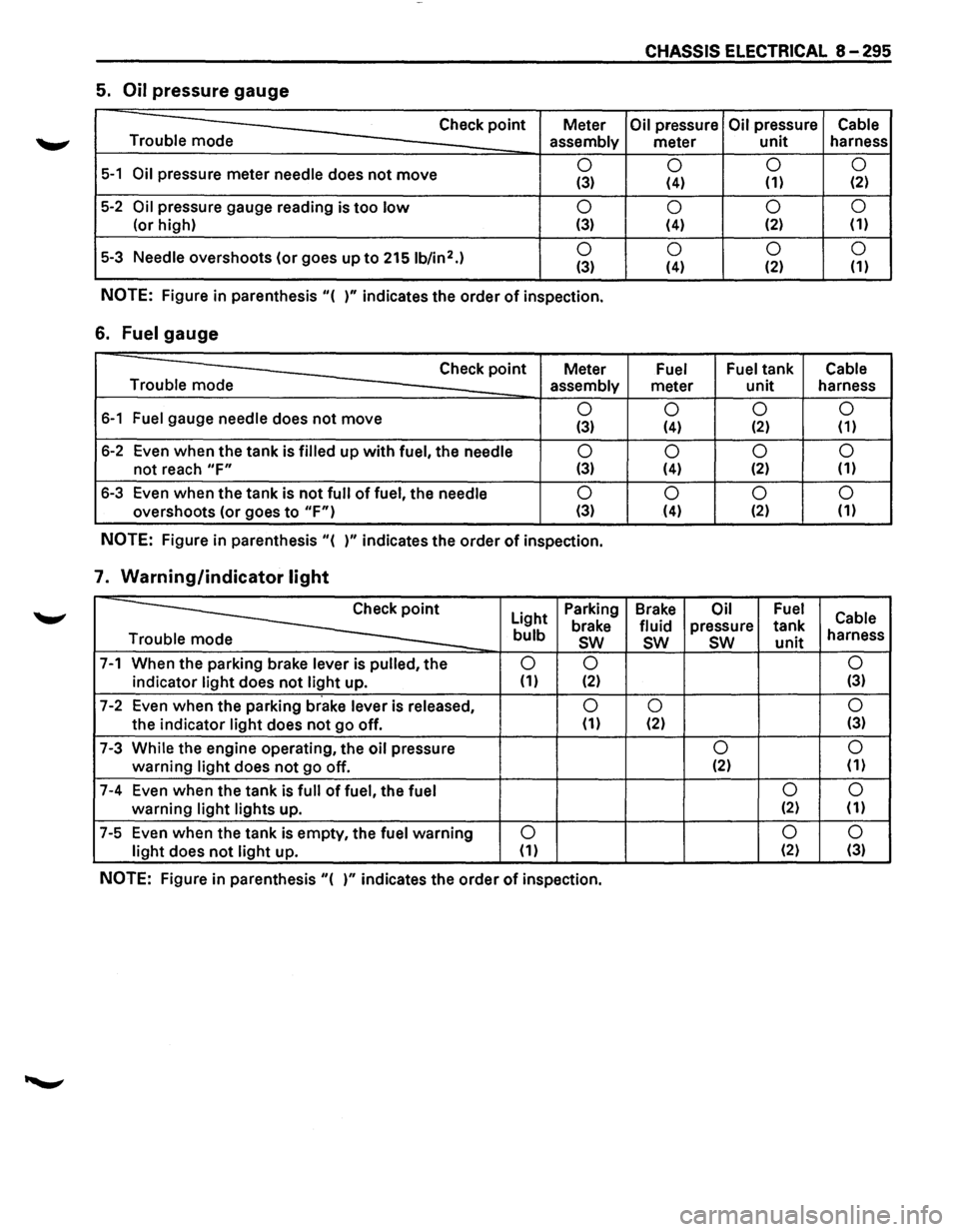
CHASSIS ELECTRICAL 8-295
5. Oil pressure gauge
Check point Meter Oil pressure Oil pressure Cable
Trouble mode
assembly meter unit harness
5-1 Oil pressure meter needle does not move 0
0 0
0 (3) (4) (1) (2)
5-2 Oil pressure
gauge reading is too low 0
0 0
0
(or
high) (3) (4) (2) (1)
5-3 Needle overshoots
(or goes up to 2151b/in2.) 0
0 0 0 (3) (4) (2)
(1)
NOTE: Figure
in parenthesis "( )" indicates the order of inspection.
6. Fuel gauge
Check point Meter Fuel Fuel tank Cable
Trouble mode assembly
meter unit harness
6-1 Fuel gauge needle does not move 0
0 0 0 (3) (4) (2) (1)
6-2 Even when the tank is filled up with fuel, the needle 0
0 0
0
not reach "F" (3) (4) (2)
(1)
6-3
Even when the tank is not full of fuel, the needle 0
0 0
0
overshoots (or goes to "F") (3) (4) (2) (1)
NOTE: Figure
in parenthesis "( )" indicates the order of inspection.
7. Warning/indicator light
~
Light Parking
Brake Oil Fuel Cable brake fluid pressure tank bulb sw sw sw unit harness
e
7-1 When the parking brake lever is pulled, the 0 0 0
indicator light does not light up. (1) (2) (3)
7-2 Even
when the parking brake lever is released, 0 0 0
the indicator light does not go off. (1) (2) (3)
7-3 While the engine operating,
the oil pressure 0 0
warning light does not go
off. (2)
(1)
7-4 Even
when the tank is full of fuel, the fuel 0 0
warning light lights
up. (2) (1)
7-5 Even
when the tank is empty, the fuel warning 0 0
0
light does not light up. (1) (2)
(3)
NOTE: Figure in parenthesis "( )" indicates the order of inspection.