check oil ISUZU TROOPER 1995 Workshop Manual
[x] Cancel search | Manufacturer: ISUZU, Model Year: 1995, Model line: TROOPER, Model: ISUZU TROOPER 1995Pages: 1928
Page 1495 of 1928
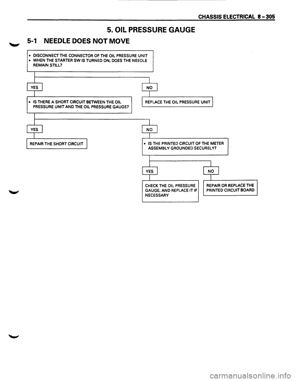
5. OIL PRESSURE GAUGE
5-1 NEEDLE DOES NOT MOVE
• DISCONNECT THE CONNECTOR OF THE OIL PRESSURE UNIT
•
WHEN THE STARTER SW IS TURNED ON, DOES THE NEEDLE REMAIN STILL?
l
J I
YES I NO I
I I
CHASSIS ElECTRICAL 8-305
• IS THERE A SHORT CIRCUIT BETWEEN THE OIL REPLACE THE OIL PRESSURE UNIT I PRESSURE UNIT AND THE OIL PRESSURE GAUGE?
I
I I
YES I NO I
I l
REPAIR THE SHORT CIRCUIT I • IS THE PRINTED CIRCUIT OF THE METER ASSEMBLY GROUNDED SECURELY?
I
I I
YES I NO I
I I
CHECK THE OIL PRESSURE REPAIR OR REPLACE THE
GAUGE, AND REPLACE IT IF PRINTED CIRCUIT BOARD
NECESSARY
Page 1496 of 1928
8-306 CHASSIS ELECTRICAL
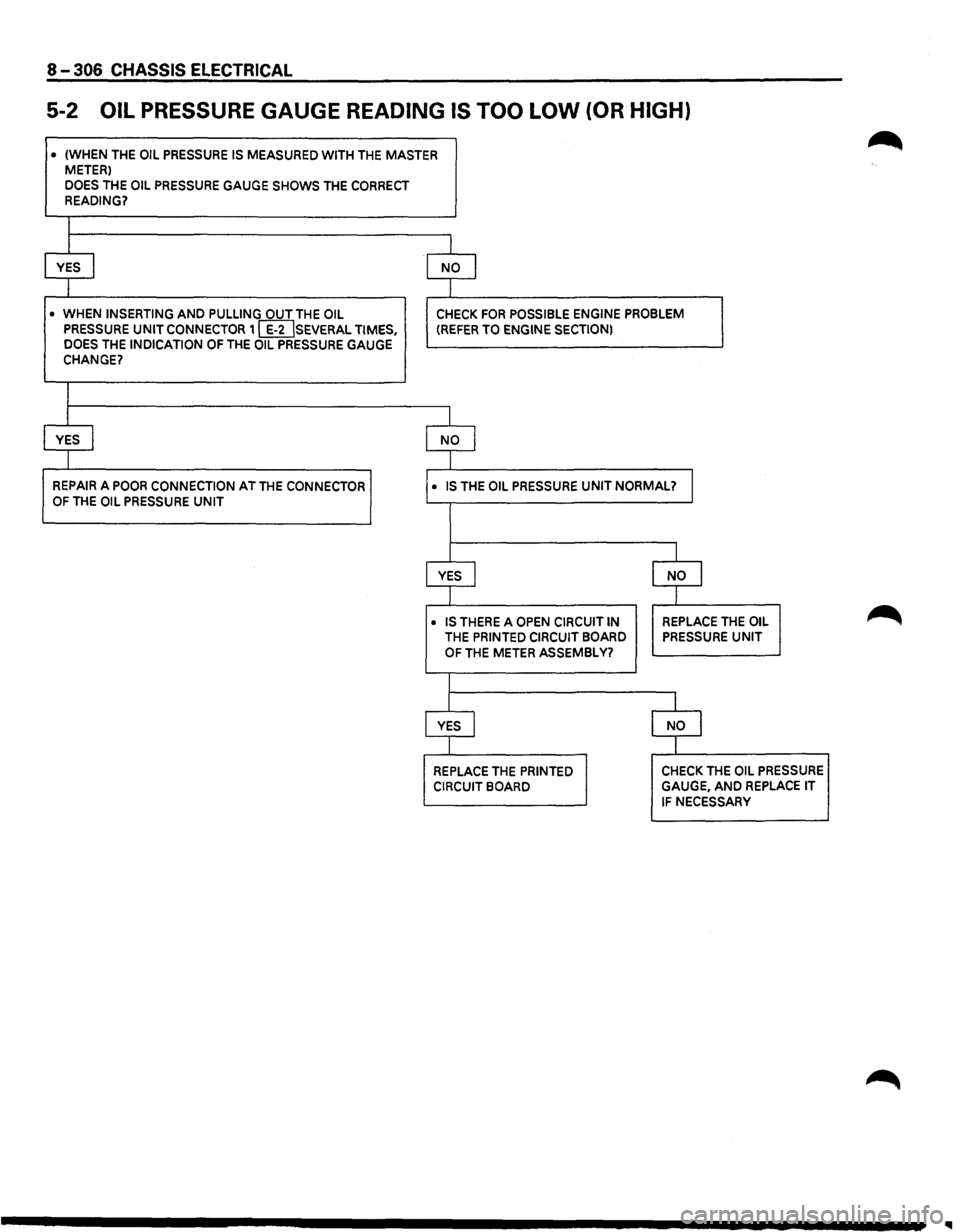
5-2 OIL PRESSURE GAUGE READING IS TOO LOW (OR HIGH)
• (WHEN THE OIL PRESSURE IS MEASURED WITH THE MASTER METER)
DOES THE OIL PRESSURE GAUGE SHOWS THE CORRECT READING?
I
I
YES I NO I
I
• WHEN INSERTING AND PULLING OUT THE OIL CHECK FOR POSSIBLE ENGINE PROBLEM PRESSURE UNIT CONNECTOR 1 [IDSEVERAL TIMES, (REFER TO ENGINE SECTION) DOES THE INDICATION OF THE OIL PRESSURE GAUGE CHANGE?
I
I
YES I NO I
I
REPAIR A POOR CONNECTION AT THE CONNECTOR • IS THE OIL PRESSURE UNIT NORMAL? I OF THE OIL PRESSURE UNIT
I
YES J NO I
I
• IS THERE A OPEN CIRCUIT IN REPLACE THE OIL
THE PRINTED CIRCUIT BOARD PRESSURE UNIT
OF THE METER ASSEMBLY?
I
YES I NO I
I
REPLACE THE PRINTED CHECK THE OIL PRESSURE
CIRCUIT BOARD GAUGE, AND REPLACE IT
IF NECESSARY
Page 1497 of 1928
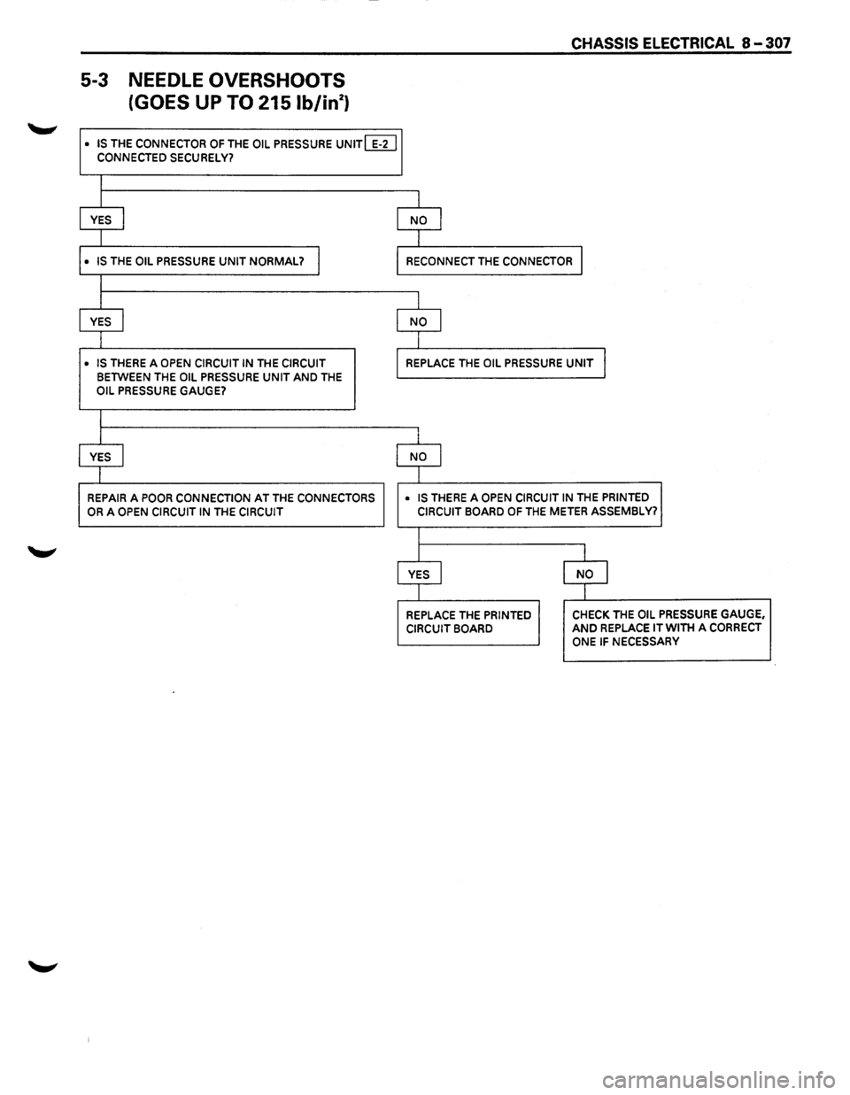
5-3 NEEDLE OVERSHOOTS
(GOES
UP TO 215 lb/in2 )
• IS THE CONNECTOR OF THE OIL PRESSURE UNIT [ILl CONNECTED SECURELY?
I
I
YES I
I
• IS THE OIL PRESSURE UNIT NORMAL? I
I
I
YES
I
• IS THERE A OPEN CIRCUIT IN THE CIRCUIT
BETWEEN THE OIL PRESSURE UNIT AND THE OIL PRESSURE GAUGE?
I
I
YES I
I
REPAIR A POOR CONNECTION AT THE CONNECTORS
OR A OPEN CIRCUIT IN THE CIRCUIT
CHASSIS ELECTRICAL 8 -307
I
NO I
I
RECONNECT THE CONNECTOR I
I
NO I
I
REPLACE THE OIL PRESSURE UNIT I
I
NO I
I
• IS THERE A OPEN CIRCUIT IN THE PRINTED CIRCUIT BOARD OF THE METER ASSEMBLY?
I
I
I
YES I NO j
I I
REPLACE THE PRINTED CHECK THE OIL PRESSURE GAUGE,
CIRCUIT BOARD AND REPLACE IT WITH A CORRECT
ONE IF NECESSARY
Page 1507 of 1928
CHASSIS ELECTRICAL 8-317
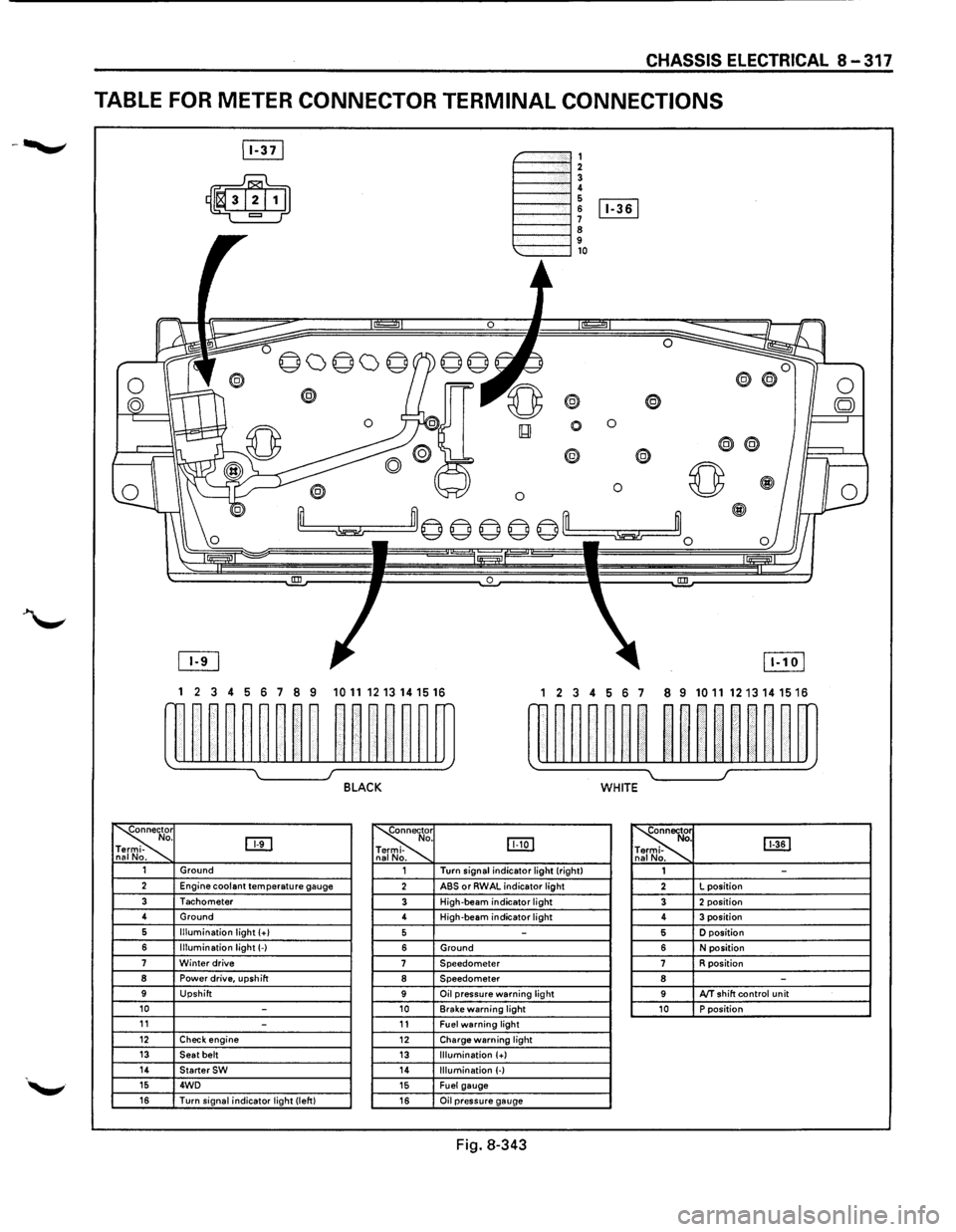
TABLE FOR METER CONNECTOR TERMINAL CONNECTIONS
~-""""""', 1----""'12 1----""'1! 6 1----l 6 [Iill
1----""'1 ~ 9 1---""'l,o
®
0 0
0
® @
0 0 ~
~m© © © © ©'--m ~~0
0 !III
1 2 3 4 5 6 7 8 9 1011 1213141516 1 2 3 4 56 7 8 9 10111213141516
w~~~~~~~~ ~~~~~~m rn~~~~~~ ~~nn~~m
~ I J BLACK WHITE
~r o. DTI -na No. ~
. IJJ:Q] -
. ~ [ill] . -. 1 Ground 1 Turn
signal indicator light (right)
1 -2 Engine coolant temperature gauge 2 ABS or RWAL indicator light 2 L
position
3 Tachometer 3 High-beam indicator light 3 2 position 4
Ground
4 High-beam
indicator light 4 3 position 6 Illumination light (+I 5 -5 D position
6 Illumination light(-) 6 Ground 6 N position 7 Winter drive 7 Speedometer 7 R position 8 Power drive, upshift 8 Speedometer 8 -9 Upshift 9 Oil pressure warning light 9 AfT shift control unit 10 -10 Brake warning light 10 P position 11 -11 Fuel warning light 12 Check engine 12 Charge warning light 13 Seat belt 13 Illumination (+) 14 StarterSW 14 Illumination (-) 15 4WD 15 Fuel gauge 16 Turn signal indicator light (left) 16 Oil pressure gauge
Fig. 8-343
Page 1521 of 1928
![ISUZU TROOPER 1995 Workshop Manual OIL PRESSURE UNIT
(1!] INSPECTION
Measure the resistance value ofthe oil pressure unit
with the circuit tester. (Fig. 8-377)
Replace the
unit when the result of inspection is found
abnorm](/img/61/57183/w960_57183-1520.png "ISUZU TROOPER 1995 Workshop Manual OIL PRESSURE UNIT
(1!] INSPECTION
Measure the resistance value ofthe oil pressure unit
with the circuit tester. (Fig. 8-377)
Replace the
unit when the result of inspection is found
abnorm")
OIL PRESSURE UNIT
(1!] INSPECTION
Measure the resistance value ofthe oil pressure unit
with the circuit tester. (Fig. 8-377)
Replace the
unit when the result of inspection is found
abnormal.
Pressure
(kPa)
Resistance value (Q)
Fig. 8-377
OIL PRESSURE SWITCH
(1!] INSPECTION
98 981
81 30
I~~ Check the continuity between the switch termi
nal and the body ground with the engine at idle.
(Fig. 8-378)
Replace the switch when the result
of inspection
is
found abnormal.
Fig. 8-378
CHASSIS ELECTRICAL 8-331
(1!] CIRCUIT INSPECTION (FIG. 8-379)
Fig. 8-379
1. Start the engine.
2. When disconnecting the oil pressure switch con
nector then connecting the harness side connec
tor to the ground, check to see if the oil pressure
warning light lights up.
When the
light will not light up, check the circuit
between the meter and the oil pressure switch,
and repair
an open circuit if necessary.
FUEL TANK UNIT
The tank unit varies the internal resistance according
to the float position (fluid level) to operate the fuel
meter needle.
It is also designed
to warn the driver of low fuel level
by illuminating the fuel warning light. (Fig. 8-380)
Fig. 8-380
Page 1632 of 1928
9J-8 Supplemental Restraint System
DEFINITIONS
AIR BAG -An inflatable cloth cushion designed to
deploy in certain frontal crashes. It supplements the
protection offered by the seat belts by distributing the
impact load more evenly over the vehicle occupant's
head and torso.
ASYNCHRONOUS -Performed in a non-periodic
fashion,i.e.no defined time or interval.
B+-Battery voltage, the voltage available at the battery
at the time of the indicated measurement. With the key
"ON" and the engine not running, the system voltage will
likely be between 12 and 12.5 volts. At idle the voltage
may be 14 to 16 volts. The voltage could be as low as 1
0
volts during engine cranking.
BULB
CHECK-The DERM will cause the "AIR BAG"
warning lamp to flash seven times and then go "OFF"
whenever the ignition switch transitions to the RUN
position from any other ignition switch position and no
malfunctions are detected.
"CONTINUOUS MONITORING"-Tests performed by
the DERM on the
SRS every 1 00 milliseconds while
"Ignition
1" voltage is in the normal operating voltage
range at the DERM.
DATA LINK CONNECTOR(DLC)-Formerly "ALDL'', a
connector which allows communication with an
off-board computer, such as a scan
tool.
DATUM LINE-A base line parallel to the plane of the
underbody or frame from which all vertical
measurements originate.
DEPLOY-To inflate the air bag.
DEPLOYMENT
LOOPS - The circuits which supply
current to the inflator modules to deploy the air bag.
DERM -Diagnostic
energy reserve module which
provides reserve energy to the deployment loops and
performs diagnostic monitoring of
all SRS components.
DIAGNOSTIC TROUBLE CODE(DTC) -Formerly
"Code,"a numerical designator used by the DERM to
indicate specific
SRS malfunctions.
DRIVER CURRENT SOURCE-An output of the DERM
which injects current into the driver inflator module circuit
during the "Initiator Assembly Resistance
Test."
DRIVER INFLATOR
MODULE-An assembly located in
the steering wheel hub consisting of an inflatable air bag,
an inflator and an initiator.
DUAL
POLE ARMING SENSOR-A sensor on the high
side(power side) of the deployment loops that is
calibrated to supply voltage to the inflator modules when
the vehicle velocity changes are severe enough to
warrant arming of the air bags in preparation for
deployment.
EEPROM -Electrically Erasable Programmable Read ~
Only Memory. Memory which retains its contents when
power
is removed from the DERM.
FORWARD LH DISCRIMINATING SENSOR-A sensor
on the low side(ground side) of the deployment loops
which is calibrated to ground the inflator modules when
the vehicle velocity changes are severe enough to
warrant deployment of the air bags.
FORWARD RH DISCRIMINATING SENSOR-A sensor
on the low side(ground side) of the deployment loops
which
is calibrated to ground the inflator modules when
the vehicle velocity changes are severe enough
to
warrant deployment of the air bag.
FORWARD LH SENSOR Eng-Room HARNESS-An
assembly of two correct carrying wires which connects
the Forward
LH discriminating sensor to SRS harness.
FORWARD RH SENSOR Eng-Room HARNESS
JUMPER-An assembly of two current carrying wires
which connects the Forward
RH discriminating sensor to
the
SRS harness.
HIGHER PRIORITY FAULT-Each diagnostic trouble
code
is assigned a priority based on the detectability with
other DTCs present. The priority corresponds to the
detectability of the malfunction ONLY, and does NOT
relate to the criticality of the malfunction with respect to ~
deployment or non-deployment under any given
condition.
IGNITION CYCLE -The voltage at the PERM "Ignition
1"
inputs, with ignition switch "ON," is within the normal
operating voltage range for at least ten seconds before
turning ignition switch
"OFF."
IGNITION1
-A battery voltage(B+)circuit which is only
powered with the ignition switch in the RUN,BULB
TEST,or START positions.
INITIATOR-The electrical component inside the inflator
module which, when sufficient current flows, sets off the
chemical reaction that inflates the air bag.
"INITIATOR ASSEMBLY RESISTANCE TEST"-Tests
performed once each ignition cycle when no
malfunctions are detected during "Turn-ON" or
"Continuous Monitoring." This test checks for the correct
DERM configuration for the vehicle, shorts to
"Ignition 1"
in the deployment loops, high resistance or opens in the
"Driver
Side High," "Driver Side Low," "Passenger Side
High"
and "Passenger Side Low" circuits and measures
the resistance of the inflator assembly consisting of: 1)
Initiators, 2) SRS coil assembly(driver side only), 3)
Connectors and associated wiring.
NORMAL OPERATING VOLTAGE RANGE-The ~
voltage measured between the DERM "Ignition 1" ·
terminals and "Ground" terminals is between 7.25 and 16
volts.
•
Page 1633 of 1928
PASSENGER CURRENT SOURCE -An output of the
DERM which injects current into the passenger inflator
module circuit during the
~Initiator Assembly Resistance
'--"" Test."
PASSENGER INFLATOR MODULE -An assembly
located in the right side of the 1/P consisting of an
inflatable bag, an inflator and an initiator.
SCAN TOOL -An off-board computer used to read
diagnostic information from on-board computers via the
data
link connector.
SERIAL DATA -Information representing the status of
the
SRS.
SRS
-Supplemental Restraint System.
SRS COIL ASSEMBLY-An assembly of two current
carrying coils in the driver deployment loop that allows
the rotation of the steering wheel while maintaining the
continuous contact
of the driver deployment loop to the
driver inflator module.
SRS WIRING HARNESS-The wires and connectors
that electrically connect the components in the
SRS.
1 Supplemental Restraint System 9J-9
"10 MINUTE LOOP TEST' -Portions of the "Initiator
Assembly Resistance Test" are repeated every ten
minutes during an ignition cycle. These are the check for
shorts to
"Ignition 1" in the deployment loops and the
check for an open discriminating sensor interconnect
circuit.
''TURN-ON" -Test which the DERM performs on the
SRS once during each ignition cycle immediately after
"Ignition 1" voltage is applied to the DERM and before
"Continuous Monitoring."
36VLR-The 36-volt loop reserve energy supplies from
the DERM which provide deployment power when
vehicle voltage is
low or lost in a frontal crash.
36 VLR DELAY
-Changing of the 36 VLR power supplies
is
inhibited briefly during "Turn-ON." This allows
detection of certain malfunctions related to "Ignition 1"
voltage which cannot be tested with 36 volts present.
Page 1636 of 1928
9J-12 Supplemental Restraint System
REPAIRS AND INSPECTIONS REQUIRED AFTER AN
ACCIDENT
NOTE
• If
any SRS components are damaged, they must be
replaced. If SRS component mounting points are
damaged, they must be
replaced.
•
Never use SRS parts from another vehicle. This
does not
include remanufactured parts purchased
from an authorized
dealer; they may be used for SRS
repairs.
• Do not attempt to service discriminating sensors, the
dual pole arming sensor, the DERM, the SRS coil
assembly,
or the inflator modules. Service of these
items is by
replacement only.
•
Verify the part number of replacement inflator
modules.
CAUTION: PROPER OPERATION OF THE
SENSORS AND SUPPLEMENTAL RESTRAINT
SYSTEM (SRS) REQUIRES THAT ANY REPAIRS TO
THE VEHICLE STRUCTURE RETURN IT TO THE
ORIGINAL PRODUCTION CONFIGURATION.
DEPLOYMENT REQUIRES, AT A MINIMUM,
REPLACEMENT OF THE SENSORS, THE INFLATOR
MODULE,
AND DIMENSIONAL INSPECTION OF THE
STEERING COLUMN. ANY VISIBLE DAMAGE TO
THE DERM MOUNTING BRACKET(S) REQUIRES
REPLACEMENT, SENSORS MUST BE REPLACED,
AND THE
STEERING COLUMN MUST BE
DIMENSIONALLY INSPECTED, WHETHER
DEPLOYMENT
OCCURRED OR NOT.
ACCIDENT WITH DEPLOYMENT-COMPONENT
REPLACEMENT AND
INSPECTIONS
Certain SRS components must be replaced for damage
after a
frontal crash involving air bag deployment. Those
components are:
• Inflator modules.
• All
sensors. It is include among the Dual pole Arming
Sensor.
CAUTION
•
Refer to "Sensor Replacement Guidelines"
below for Important Information on sensor
replacement In both deployment and
non-deployment crashes.
• SRS coil assembly, Inspect wiring and connector for
any signs of scorching,
melting, or damage due to
excessive heat.
Replace if damaged. Refer to this in
section
3.
ACCIDENT WITH OR WITHOUT DEPLOYMENT
COMPONENT INSPECTIONS
Certain SRS and restraint system components must be
inspected after any crash, whether the air bag
deployed
or not. Those components are:
• Steering column-Dimensionally inspect per
"Checking Steering Column for Accident Damage" in
section 3.
• Sensors, if in the area of accident damage. If with
deployment, All sensors must be replaced.
CAUTION
•
Refer to "Sensor Replacement Guidelines"
below for Important information on sensor
replacement in both deployment and
non-deployment crashes.
• Knee bolsters and mounting points-Inspect for any
distortion, bending, cracking, or other damage.
• 1/P steering column reinforcement plate-Inspect for
any distortion, bending, cracking, or other damage.
• liP braces-Inspect for any distortion, bending,
cracking, or other damage.
~
• Seat belts and mounting points-Refer to "Seat Belts"
in SECTION 10.
SENSOR REPLACEMENT GUIDELINES
SRS sensor replacement policy requires replacement of
the all sensors, after crash Involving Air Bag
Deployment.
WIRING DAMAGE
If any SRS wire harness is damaged, it should be
replaced. Don't repair SRS HARNESS. It is replace only.
SRS CONNECTOR {PLASTIC BODY AND
TERMINAL METAL PIN) DAMAGE
If any connector or terminal in the SRS wire harness
(except
pigtails) is damaged, it should be replaced.
SRS WIRE PIGTAIL DAMAGE
If the wiring pigtail (a wire or wires attached directly to the
device,
not by a connector)is damaged, the entire
component(with pigtail)must be replaced. Examples of
"pigtail" components are the driver inflator module, the
passenger
inflator module, the discriminating sensors,
the
dual pole arming sensor and the SRS coil assembly. ~
SRS WIRE DAMAGE
If any wire except the pigtail is damaged, the wire should
be replaced.
Ill
Page 1679 of 1928
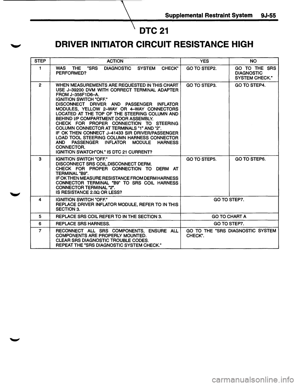
Supplemental :Restraint System 9J-55
DTC21
DRIVER INITIATOR CIRCUIT RESISTANCE HIGH
STEP ACTION YES NO
1 WAS THE "SRS
DIAGNOSTIC SYSTEM CHECK" GOTOSTEP2. GO TO THE SRS PERFORMED? DIAGNOSTIC
SYSTEM CHECK."
2 WHEN MEASUREMENTS ARE REQUESTED
IN THIS CHART GOTOSTEP3. GOTOSTEP4. USE J-39200 DVM WITH CORRECT TERMINAL ADAPTER FROM J-356F1 D6-A.
IGNITION SWITCH "OFF."
DISCONNECT DRIVER AND PASSENGER INFLATOR
MODULES, YELLOW
2-WAY OR 4--WAY CONNECTORS
LOCATED AT THE TOP OF THE STEERING COLUMN AND BEHIND 1/P COMPARTMENT DOOR ASSEMBLY.
CHECK FOR PROPER CONNECTION TO STEERING
COLUMN CONNECTOR
AT TERMINALS "1" AND "2".
IF OK THEN CONNECT J-41433 SIR DRIVER/PASSENGER
LOAD TOOL STEERING COLUMN HARNESS CONNECTOR
AND PASSENGER INFLATOR MODULE
HARNESS
CONNECTOR.
IGNITION SWATCH"ON." IS
DTC 21 CURRENT?
3
IGNITION SWITCH "OFF."
GO TO STEPS. GOTOSTEP6.
DISCONNECT SRS COIL.DISCONNECT DERM.
CHECK FOR PROPER CONNECTION TO DERM AT TERMINAL "B9".
IF OK THEN MEASURE RESISTANCE FROM DERM HARNESS
CONNECTOR TERMINAL "B9" TO SRS COIL HARNESS
CONNECTOR TERMINAL
"2". IS RESISTANCE 2.00 OR LESS?
4 IGNITION SWITCH "OFF." GOTOSTEP7. REPLACE DRIVER INFLATOR MODULE, REFER TO IN THIS
SECTION 3.
5 REPLACE SRS COIL REFER TO IN THE SECTION 3. GO TO CHART A
6 REPLACE
SRS HARNESS. GOTOSTEP7.
7
RECONNECT ALL SRS COMPONENTS, ENSURE
ALL GO TO THE "SRS DIAGNOSTIC SYSTEM
COMPONENTS ARE PROPERLY MOUNTED. CHECK". CLEAR SRS DIAGNOSTIC TROUBLE CODES.
REPEAT THE "SRS DIAGNOSTIC SYSTEM CHECK."
Page 1680 of 1928
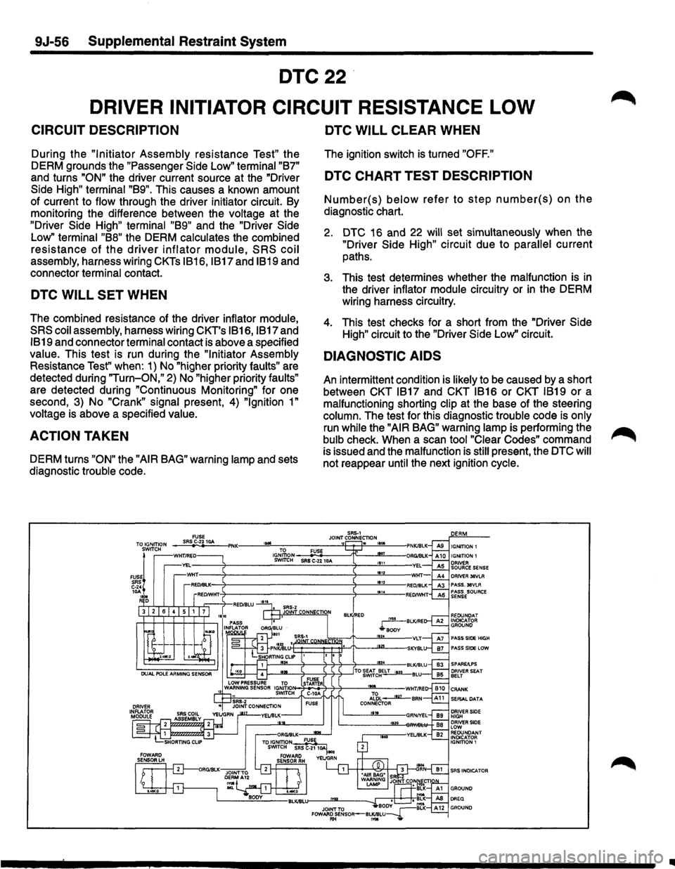
9J-56 Supplemental Restraint System
DTC22
DRIVER INITIATOR CIRCUIT RESISTANCE LOW
CIRCUIT DESCRIPTION
During the "Initiator Assembly resistance Test" the
DERM grounds the "Passenger
Side Low" terminal "B7"
and turns "ON" the driver current source at the "Driver
Side High" terminal "B9". This causes a known amount
of current to flow through the driver initiator circuit. By
monitoring the difference between the voltage at the
"Driver Side High" terminal "B9" and the "Driver Side
Low"
terminal "B8" the DERM calculates the combined
resistance of the driver inflator module, SRS coil
assembly, harness wiring CKTs IB16, IB17 and IB19 and
connector terminal contact.
DTC WILL SET WHEN
The combined resistance of the driver inflator module,
SRS coil assembly, harness wiring CKT's IB16, IB17 and
IB19 and connector terminal contact is above a specified
value. This test is run during the
"Initiator Assembly
Resistance
Test" when: 1) No "higher priority faults" are
detected during
"Turn-ON," 2) No "higher priority faults"
are detected during "Continuous Monitoring" for one
second,
3) No "Crank" signal present, 4) "Ignition 1"
voltage is above a specified value.
ACTION TAKEN
DERM turns "ON" the "AIR BAG" warning lamp and sets
diagnostic trouble code.
DTC WILL CLEAR WHEN
The ignition switch is turned "OFF."
DTC CHART TEST DESCRIPTION
Number(s) below refer to step number(s) on the
diagnostic chart.
2. DTC 16 and 22 will set simultaneously when the
"Driver Side High" circuit due to parallel current
paths.
3. This test determines whether the malfunction is in
the driver inflator module circuitry or in the DERM
wiring harness circuitry.
4. This test checks for a short from the "Driver Side
High"
circuit to the "Driver Side Low'' circuit.
DIAGNOSTIC AIDS
An intermittent condition is likely to be caused by a short
between CKT
IB17 and CKT IB16 or CKT IB19 or a
malfunctioning shorting
clip at the base of the steering
column. The test for this diagnostic trouble code is only
run while the "AIR BAG" warning lamp is performing the
bulb check. When a scan tool
"Clear Codes" command
is issued and the malfunction is
still present, the DTC will
not reappear until the next ignition cycle.
SAS·1 JOINT CONNECTlON FUSE SASC-2310A -. IGNITION 1 IGJ,\\oN FUSE SWrrtH SRS C-22 10A
DRIVER 38VLR PASS.30VLA PASS. SOURCE SENSE
REDUNOAT INOtcATOR GROUND
PASS SIDE HIGH PASS SIDE LOW
SPAREAPS
SERIAL DATA
DRIVER SIDE HIGH DRIVER SIDE LOW REDUNDANT INDICATOR
IGNITION 1
SRS INDICATOR
..