check oil ISUZU TROOPER 1995 Owners Manual
[x] Cancel search | Manufacturer: ISUZU, Model Year: 1995, Model line: TROOPER, Model: ISUZU TROOPER 1995Pages: 1928
Page 883 of 1928

AUTOMATIC TRANSMISSION (4L30-E) 7 A-11
FUNCTIONS OF INPUT /OUTPUT COMPONENTS
Components Function
Speed sensor
Senses rotation
of output shaft and feeds the data to Transmission
(fixed
to transmission (T/M)) Control Module (TCM)
Throttle Senses the extent of throttle valve opening and the speed of the throttle
position sensor (TPS) valve lever motion to open the valve and feeds the data to TCM (fed to
(fixed to engine)
Engine Control Module (ECM) also)
I
Brake Switch (SW) Senses whether the driver has pressed the brake pedal or not and feeds
N (fixed
to brake pedal) the
information to TCM
p Kick-down SW (fixed to Senses whether the driver has pushed the accelerator pedal fully or not
u accelerator pedal) and feeds the information to TCM
T Mode
SW (fixed to T/M) Senses the select lever position and feeds the information to TCM
s Power drive SW Senses whether the driver has selected the power mode and feeds the
I (fixed to front console) information to TCM
G T/M
oil temp. sensor
Senses the T/M oil temperature and feeds the data to TCM
N Engine
coolant Senses the engine cooling water temperature and feeds the data to TCM
A temperature
SW (feeds the signal from ECM)
L
Engine speed
signal Feeds the signals monitoring engine speed to TCM from Ignition Control
Module
(fed to ECM also)
Air conditioning Senses whether the air conditioner has been switched on or not and
information feeds the information
to TCM
On-board diagnostic
input By monitoring the Ground (GND), the location of failure is shown on the
T/M
monitor lamp ("CHECK TRANS") by flashing the diagnostic trouble
code
Winter switch
Senses whether the driver has selected the winter mode, and feeds the
(fixed
to front console) information to TCM
Cruise
controller Downshift takes place when Overdrive OFF signal is received from auto
(Overdrive
OFF signal) cruise control unit
Shift
solenoid Selects shift point and gear position suited to the vehicle running con-s 1-2/3-4, 2-3
dition on the basis of TCM output 0 Band apply solenoid
Controls oil flow suited to the vehicle running condition on the basis of L
E TCM output
0 N
Torque
Converter Controls clutch engagement/disengagement suited to the vehicle
u 0 Clutch solenoid running condition on the basis of TCM output
T I Force motor Adjusts the oil pump delivery pressure to line pressure suited to the p D
(Pressure regulator vehicle running condition on the basis of TCM output u valve) T
Power drive mode lamp
Informs the driver whether the vehicle is in power mode or not
s Winter drive mode lamp Informs the driver whether the vehicle is in winter mode or not
I T/M monitor lamp Informs the driver of failure in the system. It also displays the self diagnosis
G
("CHECK TRANS") code.
N Data Link Connector
(DLC) When connected with TECH 1 or tester, can communicate the data for A
L function
check, etc. (fed to ECM also). When TECH 1 is not connected, can
communicate the
signal for torque management with ECM.
Self-diagnosis connector
When short-circuited with the bipolar connector, the T/M monitor lamp
displays
a failure by code.
ATF warning
lamp Lights when ATF oil temperature rises.
ABS signal When the select lever is at "Reverse" or "L" range, sends a signal to the
ABS controller as one of the ABS control conditions.
Page 887 of 1928
AUTOMATIC TRANSMISSION (4L30-E) 7A-15
DIAGNOSIS
. .,._., INTRODUCTION
The systematic trouble shooting information covered by this Section offers a practical and systematic
approach
to diagnosing 4L30-E transmission, using information that can be obtained from road tests,
electrical diagnosis, oil pressure checks or noise evaluation.
The key to correcting a complaint is to make use of all of the available symptoms and logically letting them
direct you
to the cause.
When
dealing with automatic transmission complaints, it is best to gather as many symptoms as possible
before making the decision to remove the transmission from the vehicle.
Frequently,
the correction of the cause of the complaint does not require removal of the transmission from
the vehicle.
Page 892 of 1928
7 A-20 AUTOMATIC TRANSMISSION (4L30-E)
CHECKING TRANSMISSION FLUID
LEVEL AND CONDITION
Checking fluid level and condition (color and odor)
at
regular intervals will provide early diagnosis
information about the transmission. This inform
ation may be used to correct a condition that, if not
detected early, could result in major transmission
repairs.
IMPORTANT: When new, automatic transmission
fluid is red in color. As the vehicle is driven, the
transmission
fluid will begin to look darker in color.
The
color may eventually appear light brown.
A DARK
brown color with burnt odor may indicate
excessive
fluid deterioration and signal a need for
fluid change.
FLUID LEVEL
When adding
or changing fluid, use only DEXRON
®-Ill.
Refer to the Maintenance and Lubrication (Section 0
of this manual) for maintenance information and
servicing
interval.
\f CAUTION: DO NOT OVERFILL
Overfilling will cause foaming, loss ~f fluid,
abnormal shifting and possible damage to
the transmission.
1. Start engine and drive vehicle until normal AfT
oil operating temperature is reached:
NOTE: The automatic transmission fluid level
must be checked with the vehicle at normal
A/T oil operating temperature: 75 TO 85°C
(167 TO 185°F) MEASURED WITH TECH1 SCAN
TOOL.
Temperature will greatly affect transmission
fluid level.
If the vehicle is not at normal AfT oil operating
temperature and the proper checking
procedures are
not followed, the result could
be a false reading of the fluid level indicator
and
an incorrect adjustment of the fluid level.
2. Park vehicle on level ground.
3. Move gear selector to "Park".
4. Apply parking brake and block wheels.
5. Allow vehicle to idle for 3 minutes with all
accessories turned off.
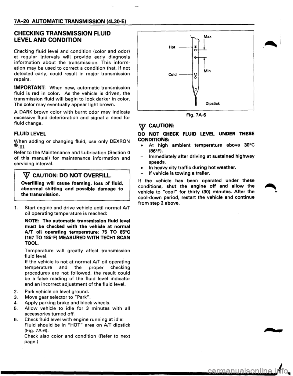
6. Check fluid level with engine running at idle:
Fluid should
be in "HOT" area on AfT dipstick
(Fig. 7A-6).
Check also color and condition (Refer to next
page.)
Hot
Cold ---IIU 0
0
Min
Dipstick
Fig. 7A-6
\f CAUTION:
DO NOT CHECK FLUID LEVEL UNDER THESE
CONDITIONS: •
At high ambient temperature above 30°C
(86°F).
Immediately after driving at sustained highway
speeds.
• In heavy city traffic during hot weather.
If vehicle is towing a trailer.
If the vehicle has been operated under these
conditions,
shut the engine off and allow the
vehicle to "cool" for thirty (30) minutes. After the
cool-down period, restart the vehicle and continue
from step 2 above.
'~I
......
Page 906 of 1928
7 A-34 AUTOMATIC TRANSMISSION (4L30-E)
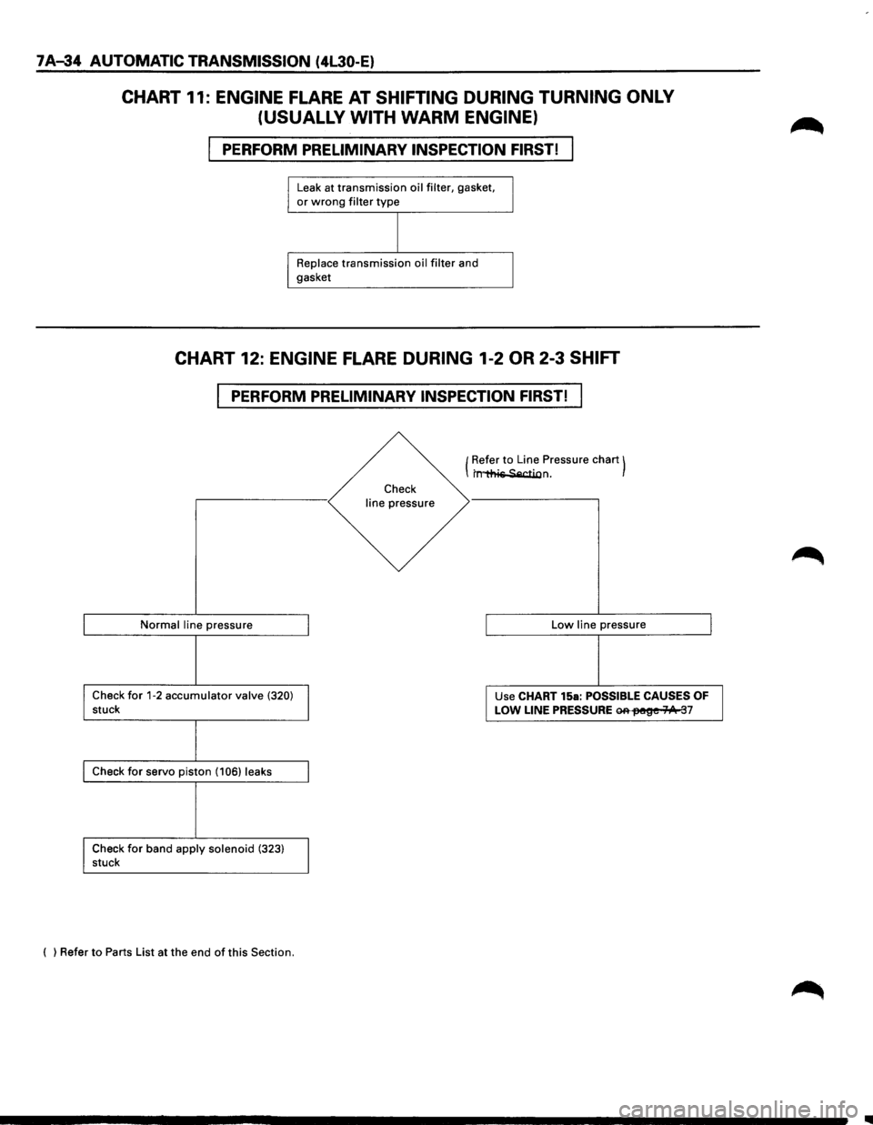
CHART 11: ENGINE FLARE AT SHIFTING DURING TURNING ONLY
(USUALLY WITH
WARM ENGINE)
PERFORM PRELIMINARY INSPECTION FIRST!
Leak at transmission oil filter, gasket, or wrong filter type
Replace transmission oil filter and
gasket
CHART 12: ENGINE FLARE DURING 1-2 OR 2-3 SHIFT
PERFORM PRELIMINARY INSPECTION FIRST!
Normal line pressure
Check for 1-2 accumulator valve (320) stuck
Check for servo piston (106) leaks
Check
for band apply solenoid (323) stuck
( ) Refer
to Parts List at the end of this Section.
Check
line pressure (
Refer
to Line
Pressure chart) t~n.
Low line pressure
Use CHART 15a:
POSSIBLE CAUSES OF
LOW LINE PRESSURE ~fM!~e 71/1t 37
..
Page 908 of 1928
7 A-36 AUTOMATIC TRANSMISSION (4L30-E)
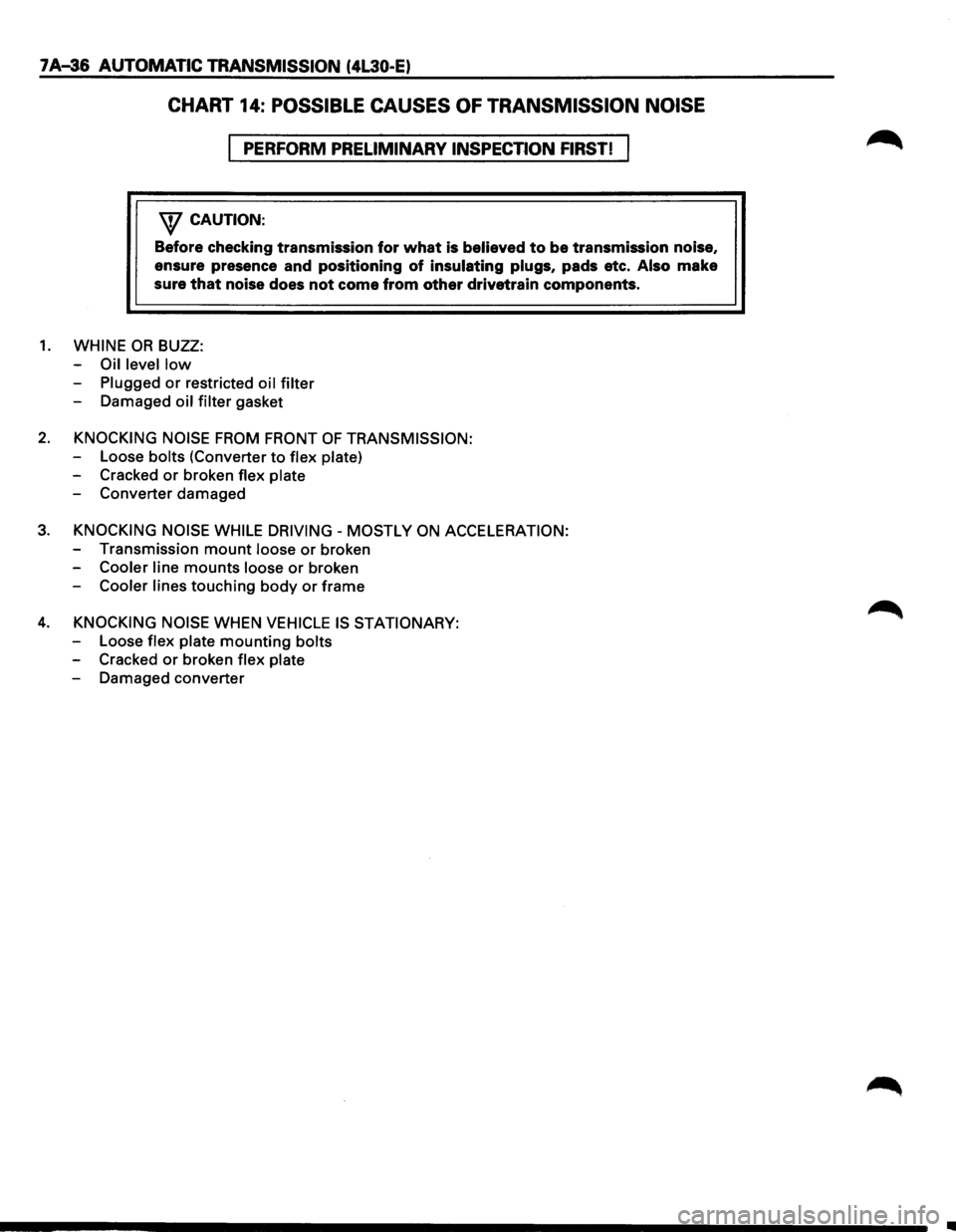
CHART 14: POSSIBLE CAUSES OF TRANSMISSION NOISE
PERFORM PRELIMINARY INSPECTION FIRST!
'\f CAUTION:
Before checking transmission for what is believed to be transmission noise,
ensure presence and
positioning of insulating plugs, pads etc. Also make
sure
that noise does not come from other drivetrain components.
1. WHINE OR BUZZ:
-
Oil level low
-Plugged or restricted oil filter
- Damaged oil filter gasket
2. KNOCKING NOISE FROM FRONT OF TRANSMISSION:
-Loose bolts (Converter to flex plate)
- Cracked or broken flex plate
-Converterdamaged
3. KNOCKING NOISE WHILE DRIVING- MOSTLY ON ACCELERATION:
-Transmission mount loose or broken
-
Cooler line mounts loose or broken
-
Cooler lines touching body or frame
4. KNOCKING NOISE WHEN VEHICLE IS STATIONARY:
-Loose flex plate mounting bolts
-Cracked or broken flex plate
-Damaged converter
II
Page 909 of 1928
w CJ s: a: w Cl)
w ..... CJ :E w > I z 0
AUTOMATIC TRANSMISSION (4L30..E) 7 A-37
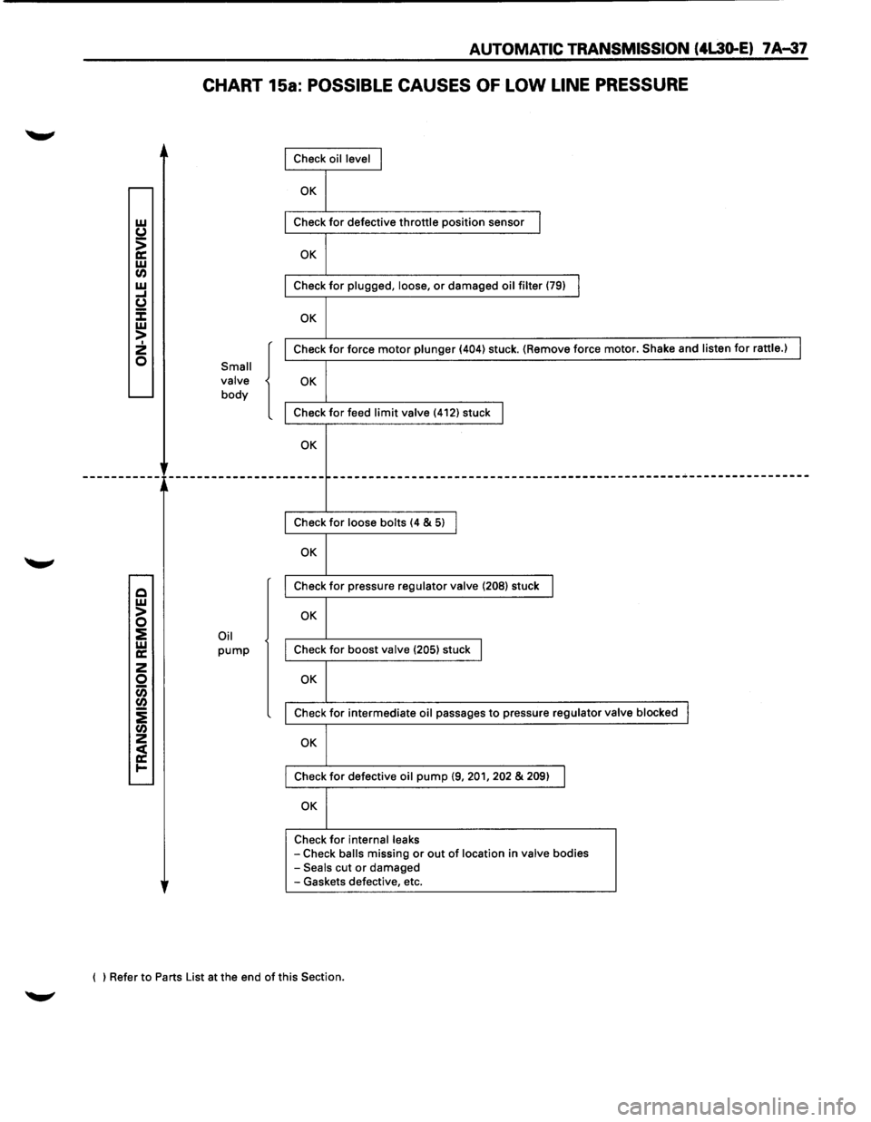
CHART 15a: POSSIBLE CAUSES OF LOW LINE PRESSURE
Small
valve
body
Oil pump
{
Check oil level I
OK
Check for defective throttle position sensor I
OK
Check for plugged, loose, or damaged oil filter (79) I
OK
Check for force motor plunger (404) stuck. (Remove force motor. Shake and listen for rattle.) I
OK
Check for feed limit valve (412) stuck I
OK
------------------------------------------------------------------------
Check for loose bolts (4 & 5) I
OK
Check for pressure regulator valve (208) stuck I
OK
Check for boost valve (205) stuck I
OK
Check for intermediate oil passages to pressure regulator valve blocked I
OK
Check for defective oil pump (9, 201, 202 & 209) I
OK
Check for internal leaks -Check balls missing or out of location in valve bodies -Seals cut or damaged
-Gaskets defective, etc.
( ) Refer to Parts List at the end
of this Section.
Page 910 of 1928
7 A-38 AUTOMATIC TRANSMISSION (4L30-E)
w (J
> a: w (I) w .... u :E w > I 2 0
Q w > 0 ::E w a:
2 0 CiS (I)
i (I) 2
~ .....
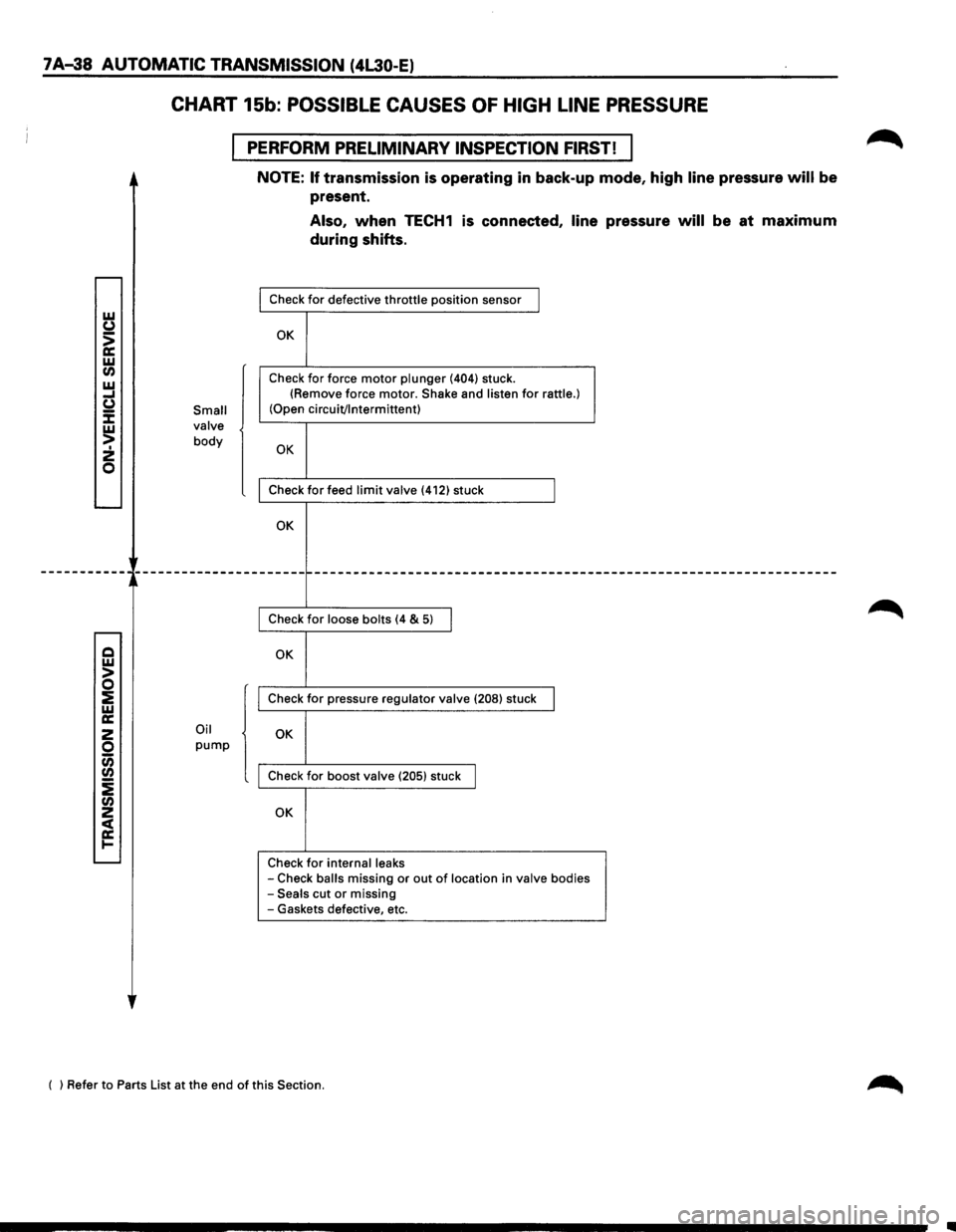
CHART 15b: POSSIBLE CAUSES OF HIGH LINE PRESSURE
PERFORM PRELIMINARY INSPECTION FIRST! I
Small
valve
body
Oil
pump
NOTE: If transmission is operating in back-up mode, high line pressure will be
present.
Also, when TECH1 is connected, line pressure will be at maximum
during shifts.
Check for defective throttle position sensor I
OK
Check for force motor plunger (404) stuck.
(Remove force motor. Shake and listen for rattle.) (Open circuit/Intermittent)
OK
Check for feed limit valve (412) stuck I
OK
--------------------------------------------
Check for loose bolts (4 & 5) I
OK
Check for pressure regulator valve (208) stuck I
OK
Check for boost valve (205) stuck I
OK
Check for internal leaks
-Check balls missing or out of location in valve bodies -Seals cut or missing
-Gaskets defective, etc.
( ) Refer to Parts List at the end
of this Section.
Page 911 of 1928
AUTOMATIC TRANSMISSION (4L30-E) 7 A-39
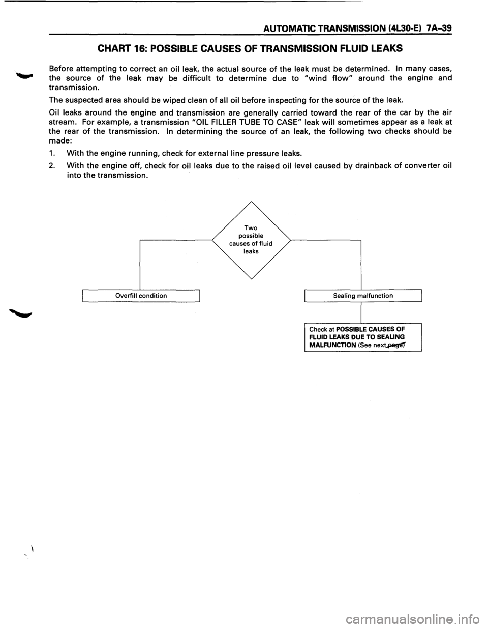
CHART 16: POSSIBLE CAUSES OF TRANSMISSION FLUID LEAKS
Before attempting to correct an oil leak, the actual source of the leak must be determined. In many cases,
the source
of the leak may be difficult to determine due to "wind flow" around the engine and
transmission.
The suspected area
should be wiped clean of all oil before inspecting for the source of the leak.
Oil leaks
around the engine and transmission are generally carried toward the rear of the car by the air
stream. For example, a transmission "OIL FILLER TUBE TO CASE" leak will sometimes appear as a leak at
the rear
of the transmission. In determining the source of an leak, the following two checks should be
made:
1. With the engine running, check for external line pressure leaks.
2. With the engine off, check for oil leaks due to the raised oil level caused by drainback of converter oil
into the transmission.
Overfill condition
Two possible causes of fluid
leaks
Sealing
malfunction
Check at POSSIBLE CAUSES OF FLUID LEAKS DUE TO SEALING
MALFUNCTION (See nex~
Page 913 of 1928
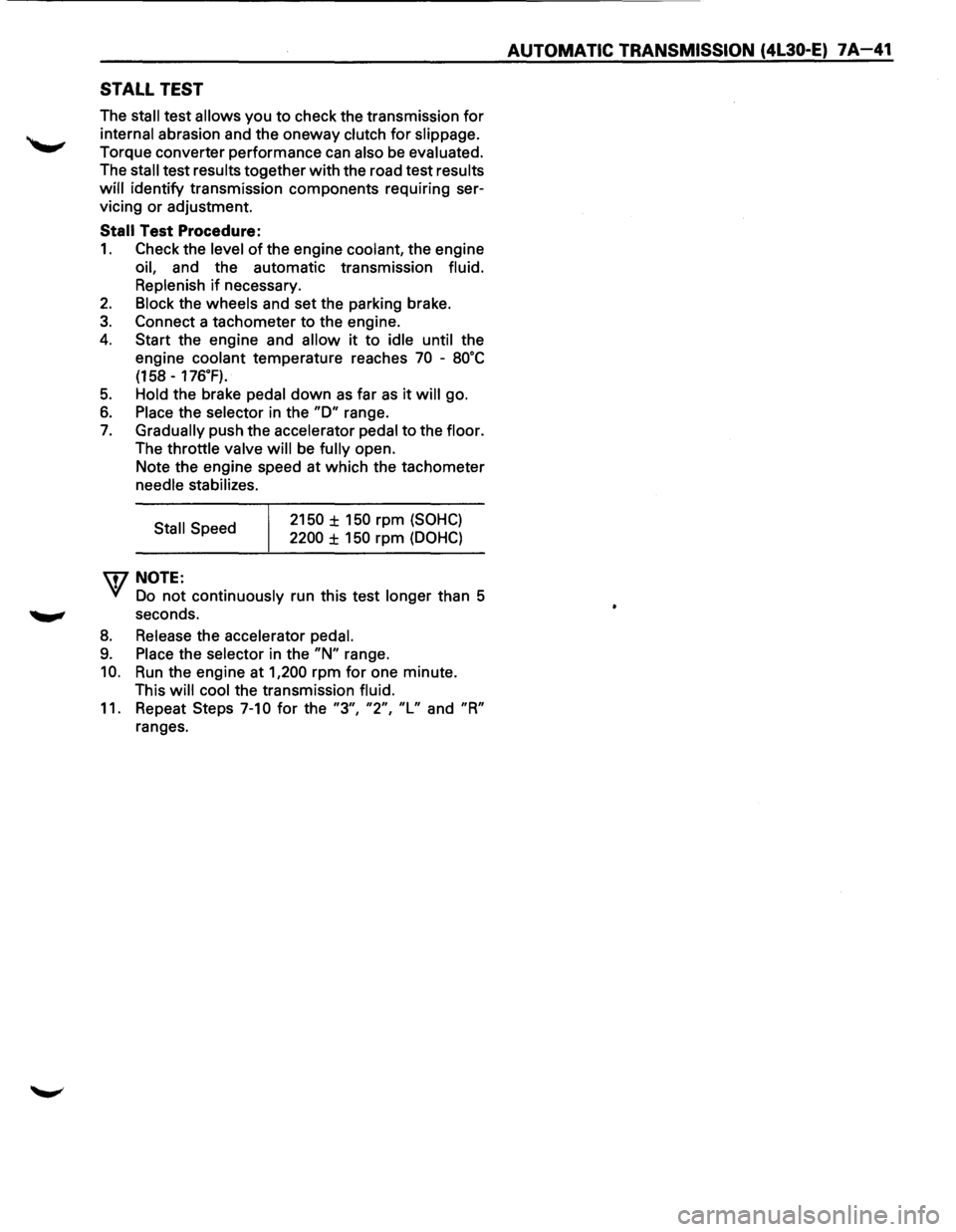
STALL TEST
The stall test allows you to check the transmission for
internal abrasion and the oneway clutch for slippage.
Torque converter performance can also be evaluated.
The
stall test results together with the road test results
will identify transmission components requiring ser
vicing or adjustment.
Stall Test Procedure:
1. Check the level of the engine coolant, the engine
oil, and the automatic transmission fluid.
Replenish
if necessary.
2. Block the wheels and set the parking brake.
3. Connect a tachometer to the engine.
4. Start the engine and allow it to idle until the
engine coolant temperature reaches
70 -8o·c
(158 -176.F).
5. Hold the brake pedal down as far as it will go.
6. Place the selector in the "D" range.
7. Gradually push the accelerator pedal to the floor.
The throttle valve
will be fully open.
Note the engine speed at which the tachometer
needle stabilizes.
Stall Speed
\fl NOTE:
2150 ± 150 rpm (SOHC)
2200 ± 150 rpm (DOHC)
VI Do not continuously run this test longer than 5
........, seconds.
8. Release the accelerator pedal.
9. Place the selector in the "N" range.
10. Run the engine at 1,200 rpm for one minute.
This
will cool the transmission fluid.
11. Repeat Steps 7-10 for the "3", "2", "L" and "R"
ranges.
AUTOMATIC TRANSMISSION (4L30-E) 7A-41
Page 914 of 1928
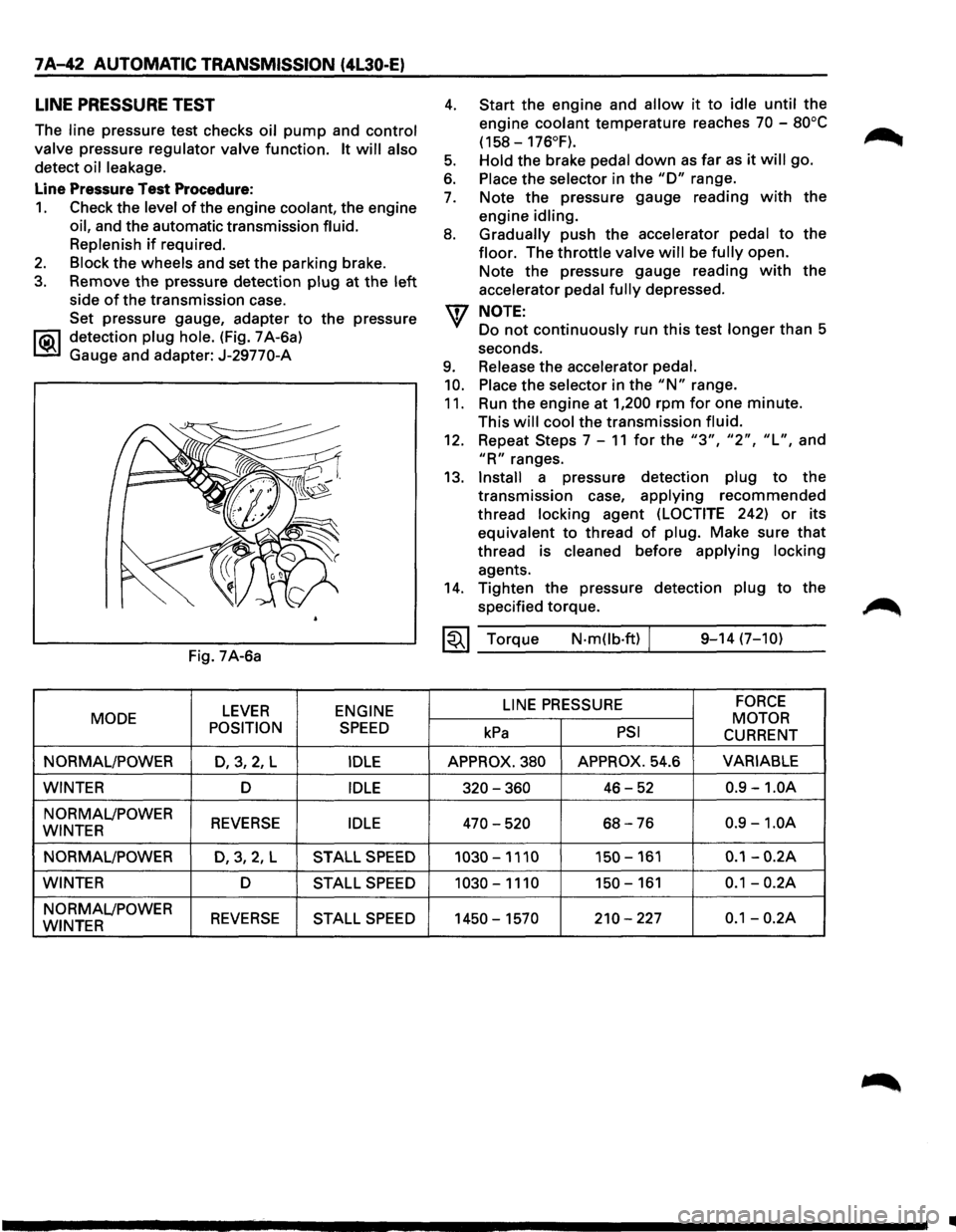
7 A-42 AUTOMATIC TRANSMISSION (4L30-E)
LINE PRESSURE TEST
The line pressure test checks oil pump and control
valve
pressure regulator valve function. It will also
detect oil leakage.
Line Pressure Test Procedure:
1. Check the level of the engine coolant, the engine
oil, and the automatic transmission fluid.
Replenish
if required.
2. Block the wheels and set the parking brake.
3. Remove the pressure detection plug at the left
side of the transmission case.
Set pressure gauge, adapter
to the pressure
l"iC\1 detection plug hole. (Fig. 7 A-6a)
~ Gauge and adapter: J-29770-A
Fig. 7A-6a
LEVER ENGINE
MODE
POSITION
SPEED
NORMAL/POWER D,3,2, L IDLE
WINTER D IDLE
NORMAL/POWER REVERSE IDLE WINTER
NORMAL/POWER
D,3,2,L STALL SPEED
WINTER D STALL SPEED
NORMAL/POWER REVERSE STALL SPEED WINTER
4.
5.
6.
7.
8.
9.
10.
11.
Start the engine and allow it to idle until the
engine
coolant temperature reaches 70 -80°C
(158-176°F).
Hold
the brake pedal down as far as it will go.
Place the selector in the "D" range.
Note the pressure gauge reading
with the
engine
idling.
Gradually
push the accelerator pedal to the
floor. The throttle valve will be fully open.
Note the pressure gauge reading
with the
accelerator
pedal fully depressed.
NOTE:
Do not continuously run this test longer than 5
seconds.
Release the accelerator pedal.
Place
the selector in the "N" range.
Run the engine at
1,200 rpm for one minute.
This
will cool the transmission fluid.
12. Repeat Steps 7-11 for the "3", "2", "L", and
"R" ranges.
13.
Install a pressure detection plug to the
transmission case,
applying recommended
thread
locking agent (LOCTITE 242) or its
equivalent to thread
of plug. Make sure that
thread is cleaned before applying locking
agents.
14. Tighten the pressure detection plug to the
specified torque.
~~~ Torque N·mOb·ft) / 9-14 (7-10)
LINE
PRESSURE FORCE
MOTOR kPa PSI CURRENT
APPROX. 380 APPROX. 54.6 VARIABLE
320-360 46-52 0.9 -1.0A
470-520 68-76 0.9 -1.0A
1030-1110 150-161 0.1-0.2A
1030-1110 150-161 0.1-0.2A
1450-1570 210-227 0.1-0.2A
•