ignition ISUZU TROOPER 1995 Workshop Manual
[x] Cancel search | Manufacturer: ISUZU, Model Year: 1995, Model line: TROOPER, Model: ISUZU TROOPER 1995Pages: 1928
Page 835 of 1928
RESULTS OF INCORRECT OPERATION
An open or ground in the Ignition Control (I C) or bypass
circuits
will set a Diagnostic Trouble Code (DTC) 42 and
cause the engine
to run on the Ignition Control Module
(ICM)
timing.
The Engine
Control Module (ECM) uses information
from the Intake Air Temperature (IAT) and engine
coolant sensors in addition to revolution per minute
(rpm) to
calculate spark advance as follows:
• Cold
engine -more spark advance.
• Engine under minimum load based on rpm and
low amount of air flow = more spark advance.
• Hot engine = less spark advance.
• Engine under heavy load based on rpm and high
air
flow = less spark advance.
HOW DIAGNOSTIC TROUBLE CODE (DTC)
42 IS DETERMINED
When the system is running on the ICM, that is, no
voltage on the bypass line, the ICM grounds (GND) the
IC signal. The ECM expects to see no voltage on the IC
line during this condition.lf it sees a voltage, it sets DTC
42 and will not go into the IC mode.
DRIVEABILITY AND EMISSIONS 6E2-139
When the rpm for IC is reached (about 400 rpm) the
ECM applies 5 volts to the bypass line and the IC should
no longer be grounded in the ICM so the IC voltage
should
be varying.
An open in the
IC circuit while running, will result in the
engine continuing to run, but in a back-up
ig~it~on
timing mode (module timing) at a calculated t1mmg
value
and the malfunction indicator lamp will not be
"ON".
If
the IC circuit is shorted to GND, the "Check Engine"
malfunction
indicator lamp will be turned "ON", and a
DTC 42 will be set and the engine will operate in
module timing. Either condition may cause poor
performance and reduced
fuel economy.
If the bypass line is open or GND, the ICM will not
switch to IC mode so the IC voltage will be low and DTC
42 will be set.
If the IC line is grounded, the ICM will switch to IC, but
because the line isGNDtherewill be no ICsignai.A DTC
42 will be set.
DIAGNOSIS
If the engine cranks but will not run, CHART A-3 will be
used to determine if the Electronic Ignition (EI) system
is the cause
of the problem or if it is another part of the
fuel injection system.
If DTC 42 is set, that DTC chart should be used for
diagnosis. If no DTC is set and the ignition system is
suspected, use
CHART C4-D ("EI" Misfire) for
diagnosis.
DIAGNOSTIC TROUBLE CODE (DTC) 12
DTC 12 is used during the on-board diagnostic system
check procedure to test the
DTC display ability of the
ECM. This diagnostic trouble code indicates that the
ECM is not receiving the engine speed (REFERENCE)
signal. This occurs with the ignition key "ON" and the
engine not running.
The "reference"
signal also triggers the fuel injection
system.
Without the "reference" signal the engine
cannot run.
ON-VEHICLE SERVICE
ELECTRONIC IGNITION (EI) ASSEMBLY
1••1 REMOVE OR DISCONNECT
1. Negative battery cable
2. "EI" electrical connectors (3)
3. Spark plug wires. (Note wire positions to proper
coils) (6)
4. "EI" assembly to bracket bolts (3)
5. "EI" assembly from Intake Plenum.
1••1 INSTALL OR CONNECT
1. "EI" assembly bracket to Intake Plenum
Tighten bolts to 25 N·m (19 lb·ft)
2. Spark plug wires to correct spark plugs
3. "EI" electrical connectors
4. Negative battery cable
Page 836 of 1928
6E2-140 DRIVEABILITY AND EMISSIONS
CRANKSHAFT POSITION (CKP) SENSOR
1••1 REMOVE OR DISCONNECT
1. Negative battery cable
2. Sensor electrical connector
3. Sensor bolts
4. Sensor from engine
11!) INSPECT
• Sensor 0-ring for wear, cracks or leakage.
Replace
if necessary. Lube new 0-ring with
engine oil before installing.
1••1 INSTALL OR CONNECT
1. Sensor in engine
2. Sensor bolt tighten to 10 Tighten bolts to 10 N·m
(88 lb·in)
3. Sensor electrical connector
4. Negative battery cable
IGNITION COIL
1••1 REMOVE OR DISCONNECT
1. Coil retaining screws (2 each coil)
2. Coil(s) from module
1••1 INSTALL OR CONNECT
1. Coil(s) to module
2. Coil retaining screws
IGNITION CONTROL MODULE (ICM)
1••1 REMOVE OR DISCONNECT
1. Negative battery cable
2. Electronic ignition assembly from Intake Plenum.
(See previous procedure)
3. Coils from assembly (Se previous procedure)
4. Module from assembly plate
1••1 INSTALL OR CONNECT
1. Module to assembly plate
2. Coils (See previous procedure)
3. "Electronic ignition" assembly to Intake Plenum
(See previous procedure)
4. Negative battery cable
IGNITION TIMING
Because the reluctor is an integral part of the
crankshaft and the crankshaft position sensor is
mounted in a fixed position,
timing adjustment is not
possible .
........................................................................\
........ ;; .
Page 838 of 1928
6E2-142 DRIVEABILITY AND EMISSIONS
CHART C-40-1
ELECTRONIC IGNITION (EI) MISFIRE AT IDLE
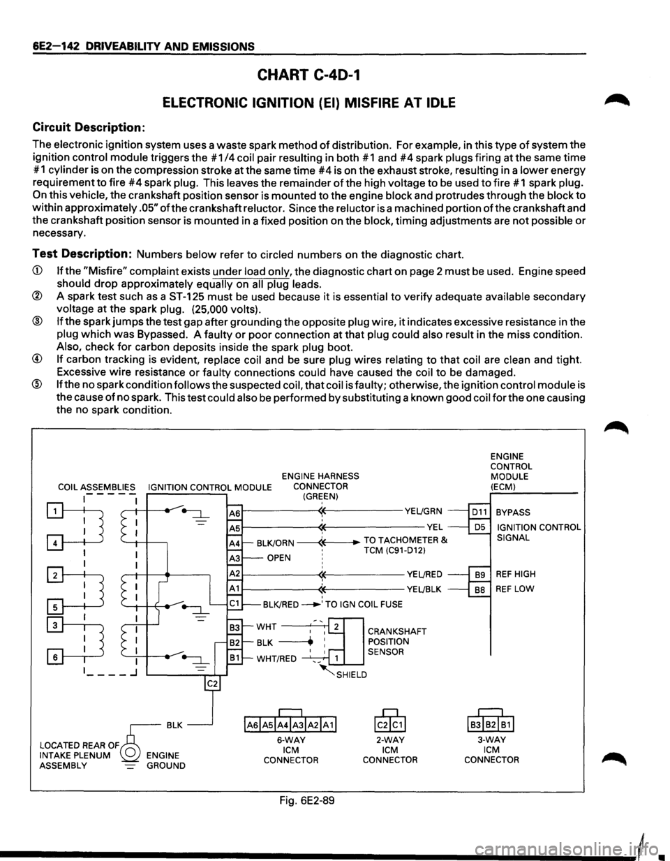
Circuit Description:
The electronic ignition system uses a waste spark method of distribution. For example, in this type of system the
ignition
control module triggers the #1 /4 coil pair resulting in both #1 and #4 spark plugs firing at the same time
# 1
cylinder is on the compression stroke at the same time #4 is on the exhaust stroke, resulting in a lower energy
requirement
to fire #4 spark plug. This leaves the remainder of the high voltage to be used to fire # 1 spark plug.
On this vehicle, the crankshaft position sensor is mounted to the engine block and protrudes through the block to
within approximately .05" ofthe crankshaft reluctor. Since the reluctor is a machined portion ofthe crankshaft and
the crankshaft position sensor is mounted in a fixed position on the
block, timing adjustments are not possible or
necessary.
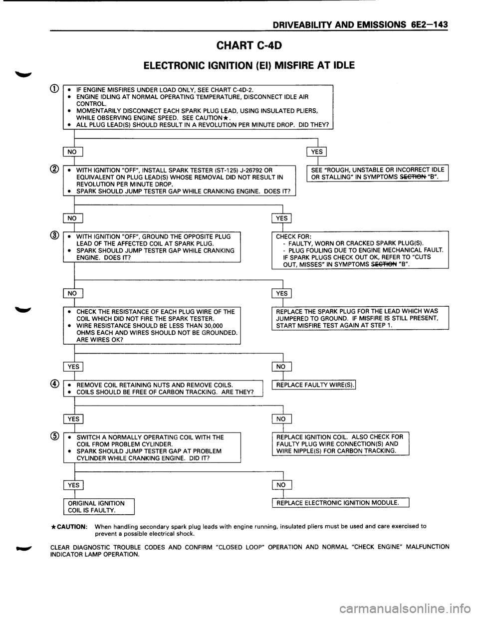
Test Description: Numbers below refer to circled numbers on the diagnostic chart.
CD If the "Misfire" complaint exists under load only, the diagnostic chart on page 2 must be used. Engine speed
should drop approximately equally on all plug leads.
® A spark test such as a ST-125 must be used because it is essential to verify adequate available secondary
voltage at the spark plug. (25,000 volts).
@ If the spark jumps the test gap after grounding the opposite plug wire, it indicates excessive resistance in the
plug which was Bypassed. A faulty or poor connection at that plug could also result in the miss condition.
Also, check for carbon deposits inside the spark plug boot.
@ If carbon tracking is evident, replace coil and be sure plug wires relating to that coil are clean and tight.
Excessive
wire resistance or faulty connections could have caused the coil to be damaged.
@ If the no spark condition follows the suspected coil, that coil is faulty; otherwise, the ignition control module is
the cause
of no spark. This test could also be performed by substituting a known good coil for the one causing
the no spark condition.
ENGINE HARNESS
COIL ASSEMBLIES IGNITION CONTROL MODULE CONNECTOR
1-- - - -(GREEN)
~ '--1-1 -+---,
I
:TI
:D
r---------~~----------YE~GRN
~--------~~-------------VEL ' BLKJORN -----4---+-TO TACHOMETER & •
TCM (C91-D12) OPEN ! ' r---------~~----------YE~RED
r-----------<1~----------YEL!BLK ' BLKJRED ___..,TO IGN COIL FUSE
IAsiAsl;rJIA21A 1!
6-WAY ICM
CONNECTOR
Fig. 6E2-89
CRANKSHAFT
POSITION
SENSOR
lc0§,1
2-WAY ICM
CONNECTOR ENGINE
CONTROL
MODULE
(ECM)
BYPASS IGNITION CONTROL
SIGNAL
REF HIGH
REF LOW
IB!IB2I~1I
3-WAY ICM CONNECTOR
Page 839 of 1928
DRIVEABILITV AND EMISSIONS 6E2-143
CHART C-40
ELECTRONIC IGNITION (EI) MISFIRE AT IDLE
CD • IF ENGINE MISFIRES UNDER LOAD ONLY, SEE CHART C-4D-2. • ENGINE IDLING AT NORMAL OPERATING TEMPERATURE, DISCONNECT IDLE AIR CONTROL. • MOMENTARILY DISCONNECT EACH SPARK PLUG LEAD, USING INSULATED PLIERS,
WHILE OBSERVING ENGINE SPEED. SEE CAUTION*. • ALL PLUG LEAD(S) SHOULD RESULT IN A REVOLUTION PER MINUTE DROP. DID THEY?
$ $
•
WITH IGNITION "OFF", INSTALL SPARK TESTER (ST-125) J-26792 OR I SEE "ROUGH, UNSTABLE OR INCORRECT IDLE
EQUIVALENT ON PLUG LEAD(S) WHOSE REMOVAL DID NOT RESULT IN OR STALLING" IN SYMPTOMS Si€'FISN "B". REVOLUTION PER MINUTE DROP. • SPARK SHOULD JUMP TESTER GAP WHILE CRANKING ENGINE. DOES IT?
$ $
•
WITH IGNITION "OFF", GROUND THE OPPOSITE PLUG CHECK FOR: @
LEAD OF THE AFFECTED COIL AT SPARK PLUG. -
FAUL TV, WORN OR CRACKED SPARK PLUG(S). • SPARK SHOULD JUMP TESTER GAP WHILE CRANKING -PLUG FOULING DUE TO ENGINE MECHANICAL FAULT. ENGINE. DOES IT? IF SPARK PLUGS CHECK OUT OK, REFER TO "CUTS
OUT, MISSES" IN SYMPTOMS SiC'flet~ "B".
~ $
• CHECK THE RESISTANCE OF EACH PLUG WIRE OF THE REPLACE
THE SPARK PLUG FOR THE LEAD WHICH WAS COIL WHICH DID NOT FIRE THE SPARK TESTER. JUMPERED TO GROUND. IF MISFIRE
IS STILL PRESENT, • WIRE RESISTANCE SHOULD BE LESS THAN 30,000 START MISFIRE TEST AGAIN AT STEP 1. OHMS EACH AND WIRES SHOULD NOT BE GROUNDED.
ARE WIRES OK?
$ $
• REMOVE COIL RETAINING NUTS AND REMOVE COILS.
I
REPLACE FAUL TV WIRE(S).I
• COILS SHOULD BE FREE OF CARBON TRACKING. ARE THEY?
$ $
•
SWITCH A NORMALLY OPERATING COIL WITH THE REPLACE IGNITION
COIL. ALSO CHECK FOR COIL FROM PROBLEM CYLINDER. FAULTY PLUG WIRE CONNECTION(S) AND • SPARK SHOULD JUMP TESTER GAP AT PROBLEM WIRE NIPPLE(S) FOR CARBON TRACKING.
CYLINDER WHILE CRANKING ENGINE. DID IT?
$ $
ORIGINAL IGNITION
I
REPLACE ELECTRONIC IGNITION MODULE. COIL IS FAUL TV.
*CAUTION: When handling secondary spark plug leads with engine running, insulated pliers must be used and care exercised to
prevent a possible electrical shock.
CLEAR DIAGNOSTIC TROUBLE CODES AND CONFIRM "CLOSED LOOP" OPERATION AND NORMAL "CHECK ENGINE" MALFUNCTION
INDICATOR LAMP OPERATION.
Page 840 of 1928
6E2-144 DRIVEABILITY AND EMISSIONS
CHART C-40-2
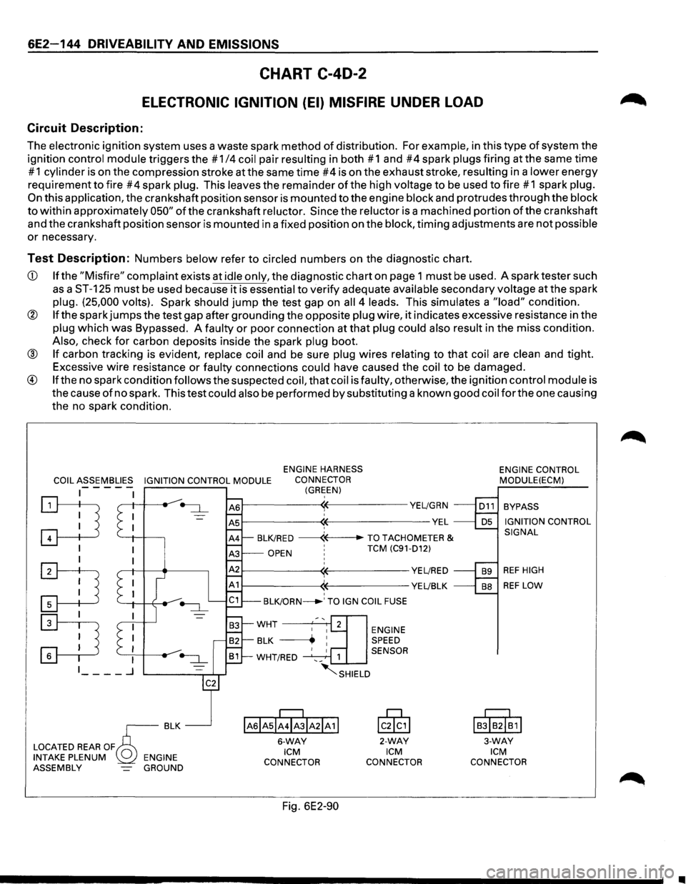
ELECTRONIC IGNITION (EI) MISFIRE UNDER LOAD
Circuit Description:
The electronic ignition system uses a waste spark method of distribution. For example, in this type of system the
ignition
control module triggers the # 1/4 coil pair resulting in both # 1 and #4 spark plugs firing at the same time
# 1 cylinder is on the compression stroke at the same time #4 is on the exhaust stroke, resulting in a lower energy
requirement
to fire #4 spark plug. This leaves the remainder of the high voltage to be used to fire #1 spark plug.
On this application, the crankshaft position sensor is mounted to the engine block and protrudes through the block
to within approximately 050" of the crankshaft reluctor. Since the reluctor is a machined portion of the crankshaft
and the crankshaft position sensor is mounted in a fixed position on the
block, timing adjustments are not possible
or necessary.
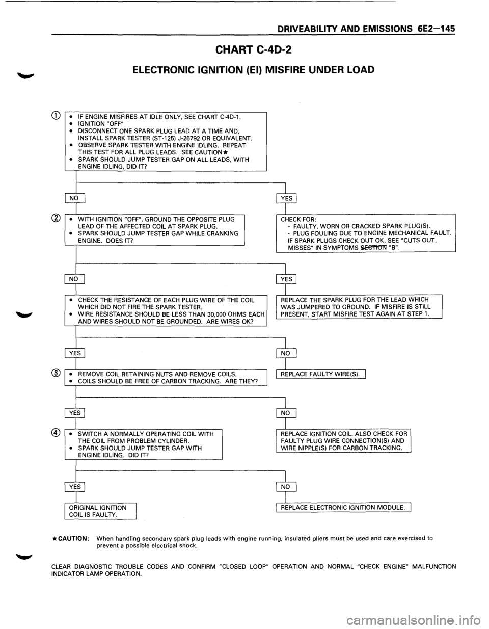
Test Description: Numbers below refer to circled numbers on the diagnostic chart.
CD If the "Misfire" complaint exists at idle only, the diagnostic chart on page 1 must be used. A spark tester such
as a ST-125 must be used because it is essential to verify adequate available secondary voltage at the spark
plug. (25,000 volts). Spark should jump the test gap on all 4 leads. This simulates a "load" condition.
® If the spark jumps the test gap after grounding the opposite plug wire, it indicates excessive resistance in the
plug which was Bypassed. A faulty or poor connection at that plug could also result in the miss condition.
Also, check for carbon deposits inside the spark plug boot.
® If carbon tracking is evident, replace coil and be sure plug wires relating to that coil are clean and tight.
Excessive
wire resistance or faulty connections could have caused the coil to be damaged.
® If the no spark condition follows the suspected coil, that coil is faulty, otherwise, the ignition control module is
the cause
of no spark. This test could also be performed by substituting a known good coil for the one causing
the no spark condition.
COIL ASSEMBLIES IGNITION CONTROL MODULE
ENGINE HARNESS
CONNECTOR
(GREEN) -----
:TI '--+I -l-----,
I
:TI
~
~--------~~-----------YE~GRN
~--------~~--------------VEL ' BLK/RED ------«--TO TACHOMETER &
OPEN ' TCM (C91-D12)
~--------~~-----------YE~RED
1------------((-----------YE~BLK ' BLK/ORN_.' TO IGN COIL FUSE
ENGINE SPEED
1 SENSOR
~SHIELD
IAsiAsii4ibiA21A11
6-WAY ICM
CONNECTOR
Fig. 6E2-90
lcik,l
2-WAY ICM
CONNECTOR ENGINE
CONTROL
MODULE(ECM)
BYPASS
IGNITION CONTROL
SIGNAL
REF HIGH
REF LOW
I
BJIB2I~1I
3-WAY ICM
CONNECTOR
•
Page 841 of 1928
DRIVEABILITV AND EMISSIONS 6E2-145
CHART C-40-2
ELECTRONIC IGNITION (EI) MISFIRE UNDER LOAD
CD • IF ENGINE MISFIRES AT IDLE ONLY, SEE CHART C-4D-1. • IGNITION "OFF"
• DISCONNECT ONE SPARK PLUG LEAD AT A TIME AND,
INSTALL SPARK TESTER (ST-125) J-26792 OR EQUIVALENT.
• OBSERVE SPARK TESTER WITH ENGINE IDLING. REPEAT THIS TEST FOR ALL PLUG LEADS. SEE CAUTION* • SPARK SHOULD JUMP TESTER GAP ON ALL LEADS, WITH
ENGINE IDLING, DID IT?
~ $
• WITH IGNITION "OFF", GROUND THE OPPOSITE PLUG CHECK FOR: LEAD OF THE AFFECTED COIL AT SPARK PLUG. -
FAUL TV, WORN OR CRACKED SPARK PLUG(S). • SPARK SHOULD JUMP TESTER GAP WHILE CRANKING -PLUG FOULING DUE TO ENGINE MECHANICAL FAULT. ENGINE. DOES IT? IF SPARK PLUGS CHECK OUT OK, SEE "CUTS OUT,
MISSES" IN SYMPTOMS SEe'l'tO'I'Q' "B".
~ $
• CHECK THE RESISTANCE OF EACH PLUG WIRE OF THE COIL REPLACE THE SPARK PLUG FOR THE LEAD WHICH
WHICH DID NOT FIRE THE SPARK TESTER. WAS JUMPERED TO GROUND. IF MISFIRE IS STILL
• WIRE RESISTANCE SHOULD BE LESS THAN 30,000 OHMS EACH PRESENT, START MISFIRE TEST AGAIN AT STEP 1. AND WIRES SHOULD NOT BE GROUNDED. ARE WIRES OK?
~ $
• REMOVE COIL RETAINING NUTS AND REMOVE COILS. REPLACE FAUL TV WIRE(S). I ® • COILS SHOULD BE FREE OF CARBON TRACKING. ARE THEY?
$ $
• SWITCH A NORMALLY OPERATING COIL WITH REPLACE IGNITION COIL. ALSO CHECK FOR THE COIL FROM PROBLEM CYLINDER. FAUL TV PLUG WIRE CONNECTION(S) AND • SPARK SHOULD JUMP TESTER GAP WITH WIRE
NIPPLE(S) FOR CARBON TRACKING.
ENGINE IDLING. DID IT?
:r ~ ORIGINAL IGNITION
I
REPLACE ELECTRONIC IGNITION MODULE. COIL IS FAUL TV.
*CAUTION: When handling secondary spark plug leads with engine running, insulated pliers must be used and care exercised to prevent a possible electrical shock.
CLEAR
DIAGNOSTIC TROUBLE CODES AND CONFIRM "CLOSED LOOP" OPERATION AND NORMAL "CHECK ENGINE" MALFUNCTION
INDICATOR LAMP OPERATION.
Page 842 of 1928
6E2-146 DRIVEABILITY AND EMISSIONS
SECTION C-5
KNOCK SENSOR (KS) SYSTEM
(DOHC ONLY)
CONTENTS
General Description ..................... 6E2-146 On-Vehicle Service ...................... 6E2-147
Purpose
............................ 6E2-146 Knock Sensor (KS) System ............... 6E2-147
Operation . . . . . . . . . . . . . . . . . . . . . . . . . . . 6E2-146 Knock
Sensor
(KS) Module .............. 6E2-147
Diagnosis
............................. 6E2-146 Chart C-5 Knock Sensor (KS) System Check ... 6E2-148
Results
Of Incorrect Knock Sensor (KS)
System Operation .................... 6E2-146
GENERAL DESCRIPTION
PURPOSE
To control spark knock, a Knock Sensor (KS) system
has been added. This system is designed to retard
spark timing up to
20·, to reduce spark knock in the
engine. This
allows the engine to use maximum spark
advance to improve driveability and fuel economy.
Varying octane
levels in gasoline can cause detonation
in engines. Detonation
is called spark knock.
OPERATION
The KS system has two major components:
• KS Module
• KS System
The sensor is mounted in the engine block under the
Intake Manifold assembly. When the KS detects
abnormal vibration (spark knocking) in the engine,
it
produced a voltage that is received by the KS module.
As long
as the KS module sees no voltage from the KS
(knock not present), it sends a signal voltage (8 to 10
volts) to the Engine Control Module (ECM) and the ECM
provides normal spark advance.
When the module detects voltage
from the KS (knock
present),
it turns "OFF" the signal to the ECM and the
voltage at terminal
"D1 0" goes toO volts. The ECM then
retards ignition control
(IC) to reduce spark knock.
The
KS signal line has a shield wire to prevent any false
signals to the
KS module. If the shield wire loses it
ground a false diagnostic trouble code (DTC) 43 may
result
or the ignition timing maybe retard needlessly.
DIAGNOSIS
RESULTS OF INCORRECT KNOCK SENSOR
(KS) SYSTEM OPERATION
Loss of the KS signal or loss of ground at KS module
would cause the signal to the ECM to remain high. This
condition
would cause the ECM to control IC, as if no
spark knocking were happening. No retard
would
occur, and spark knocking could become severe under
heavy engine load conditions. Loss
of the KS signal
to the ECM would cause the ECM
to constantly retard IC. This could result in sluggish
performance and cause a
DTC 43 to set.
A
"Scan tool" will read KC signal in A/D counts. When
detonation is detected,
KC signal counts will
increment, as long as knock is present. "Scan tools"
will
indicate knock being present either by showing
AID counts, or displaying "Yes" (knock present), or
"No" (knock not present). If DTC 43 is present, use that
chart to diagnose system. If no DTC is present and KS
system is suspected, use CHART C-5.
•
Page 848 of 1928
6E2-152 DRIVEABILITV AND EMISSIONS
EXHAUST GAS RECIRCULATION (EGR)
VALVE
CHECK
1. Engine operating a normal temperature 60oC
(120°F).
2. Place finger on Exhaust Gas Recirculation (EGR)
valve diaphragm and accelerate engine,
diaphragm
should move.
3. Disconnect vacuum hose from EGR valve.
4. Apply 10" inches of vacuum using a vacuum
pump to valve with finger on diaphragm. It should
move and engine may stall.
5. If valve passes the above test use CHART C-7 A. If
valve fails, replace valve.
EXHAUST GAS RECIRCULATION (EGR)
BACK PRESSURE TRANSDUCER (BPT)
CHECK
1. Remove vacuum hoses (3) from modulator.
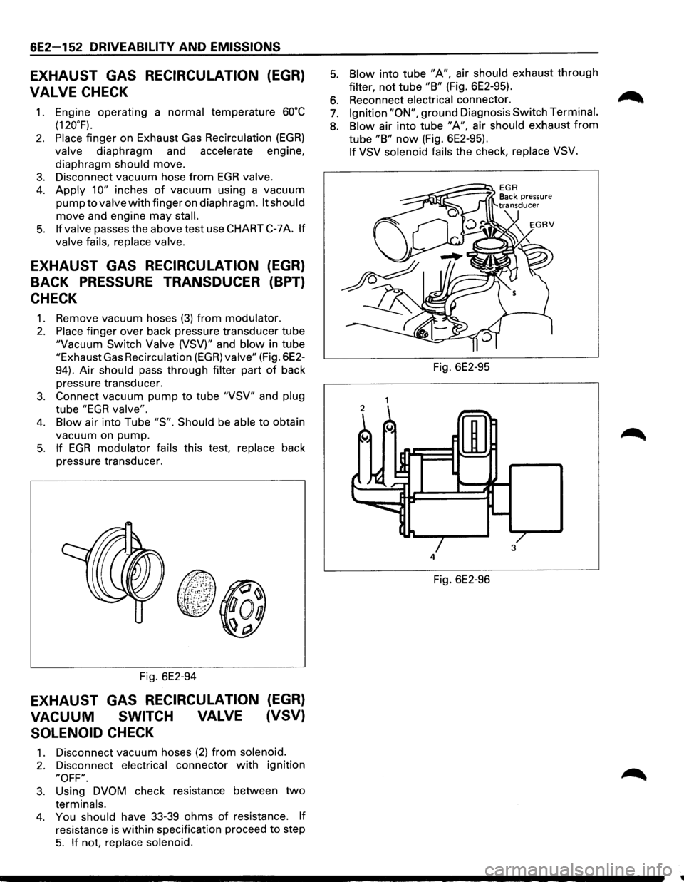
2. Place finger over back pressure transducer tube
"Vacuum Switch Valve (VSV)" and blow in tube
"Exhaust Gas Recirculation (EGR) valve" (Fig. 6E2-
94).
Air should pass through filter part of back
pressure transducer.
3. Connect vacuum pump to tube "VSV" and plug
tube "EGR valve".
4. Blow air into Tube "S". Should be able to obtain
vacuum on pump.
5. If EGR modulator fails this test, replace back
pressure transducer.
Fig. 6E2-94
EXHAUST GAS RECIRCULATION (EGR)
VACUUM SWITCH VALVE (VSV)
SOLENOID
CHECK
1. Disconnect vacuum hoses (2) from solenoid.
2. Disconnect electrical connector with ignition
"OFF".
3. Using DVOM check resistance between two
terminals.
4. You should have 33-39 ohms of resistance. If
resistance is within specification proceed to step
5. If not, replace solenoid.
5. Blow into tube "A", air should exhaust through
filter, not tube "B" (Fig. 6E2-95).
6. Reconnect electrical connector. ~
7. Ignition "ON", ground Diagnosis Switch Terminal.
8. Blow air into tube "A", air should exhaust from
tube "B" now (Fig. 6E2-95).
If VSV solenoid fails the check, replace VSV.
Fig. 6E2-95
4
Fig. 6E2-96
•
Page 854 of 1928
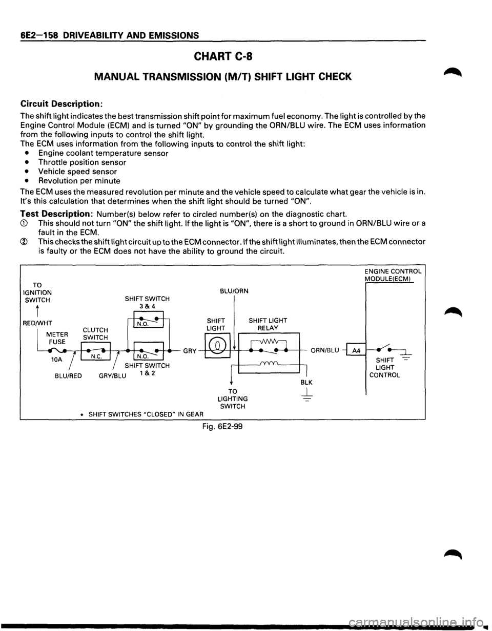
6E2-158 DRIVEABILITV AND EMISSIONS
CHART C-8
MANUAL TRANSMISSION (M/T) SHIFT LIGHT CHECK
Circuit Description:
The shift light indicates the best transmission shift point for maximum fuel economy. The light is controlled by the
Engine Control Module
(ECM) and is turned "ON" by grounding the ORN/BLU wire. The ECM uses information
from the following inputs to control the shift light.
The
ECM uses information from the following inputs to control the shift light:
• Engine coolant temperature sensor
• Throttle position sensor
• Vehicle speed sensor
• Revolution per minute
The
ECM uses the measured revolution per minute and the vehicle speed to calculate what gear the vehicle is in.
It's this calculation that determines when the shift light should be turned "ON".
Test Description: Number(s) below refer to circled number(s) on the diagnostic chart.
ECM.
® This checks the shift light circuit up to the ECM connector .If the shift light illuminates, then the ECM connector
is faulty
or the ECM does not have the ability to ground the circuit.
TO
IGNITION SWITCH
t
BLU/RED GRY/BLU
•
SHIFT SWITCHES #CLOSED" IN GEAR
BLU/ORN
SHIFT SHIFT LIGHT
LIGHT
RELAY
TO
LIGHTING SWITCH
Fig. 6E2-99
ENGINE CONTROL
MODULE(ECMl
SHIFT
LIGHT
CONTROL
Page 855 of 1928
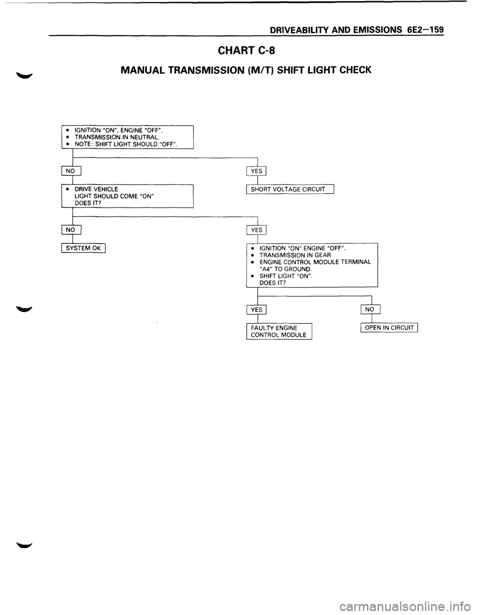
DRIVEABILITY AND EMISSIONS 6E2-159
CHART C-8
MANUAL TRANSMISSION (,MfT) SHIFT LIGHT CHECK
• IGNITION "ON", ENGINE "OFF".
• TRANSMISSION IN NEUTRAL. • NOTE: SHIFT LIGHT SHOULD "OFF".
•
DRIVE VEHICLE
LIGHT SHOULD COME "ON" DOES IT?
• IGNITION
"ON" ENGINE "OFF".
• TRANSMISSION IN GEAR • ENGINE CONTROL MODULE TERMINAL "A4" TO GROUND.
• SHIFT LIGHT "ON".
DOES
IT?