ignition ISUZU TROOPER 1995 Workshop Manual
[x] Cancel search | Manufacturer: ISUZU, Model Year: 1995, Model line: TROOPER, Model: ISUZU TROOPER 1995Pages: 1928
Page 820 of 1928
6E2-124 DRIVEABILITV AND EMISSIONS
E) REMOVAL
Preparation: • Engine hood
• Battery negative cable
1.
Air cleaner assy
2.
Accelerator pedal cable
•
Disconnect from throttle body and cable
brackets.
3. Canister vacuum hose
• Disconnect from vacuum switch valve (VSV).
4. Vacuum booster hose
• Disconnect from Common chamber duct.
5. Connectors
• Disconnect idle air control valve, throttle
position sensor, manifold absolute pressure,
canister
VSV, exhaust gas recirculation (EGR)
VSV, intake air temperature and VSV.
6. High tension cable
• Remove from cylinder heads.
7. Electronic ignition (EI) module assy
• Disconnect 3 connector from El module.
• Remove 3 bolts from El bracket and El assy.
8.
Throttle body (TB)
• Remove 4 bolts from TB.
9. Vacuum hoses
• Disconnect canister VSV and EGR VSV vacuum
hose
from TB.
10. Fuel pressure control valve vacuum hose
• Disconnect from common chamber duct.
11.
PCV hose
• Disconnect from common chamber duct.
12.
Evaporate emission canister purge hose
• Disconnect from common chamber duct.
13.
EGR valve assy
• Remove 4 bolts from common chamber duct
and exhaust manifold.
14.
Common chamber duct
• Remove 4 bolts, 4 nuts and 3 duct bracket fixing
bolts.
• Remove ground cable fixing bolt from rear of
common chamber duct.
15.
Common chamber
• Remove 6 bolts and 2 nuts.
• Remove common chamber bracket fixing bolts
from rear of common chamber.
16. Fuel
hose
• Feed and return hose from fuel pipe and 2 fixing
bolts
from cylinder head. 17.
Fuel
rail assembly
• Remove fuel injector connector.
• Remove fuel rail fixing bolts.
• Remove fuel rail assy.
j .. !•l DISASSEMBL V
NOTE:
• If
an injector becomes separated from the rail and
remains in the cylinder head, both injector
0-ring
seals and the retainer clip must be replaced.
1.
Regulator attaching screw
2. Fuel pressure control valve assembly
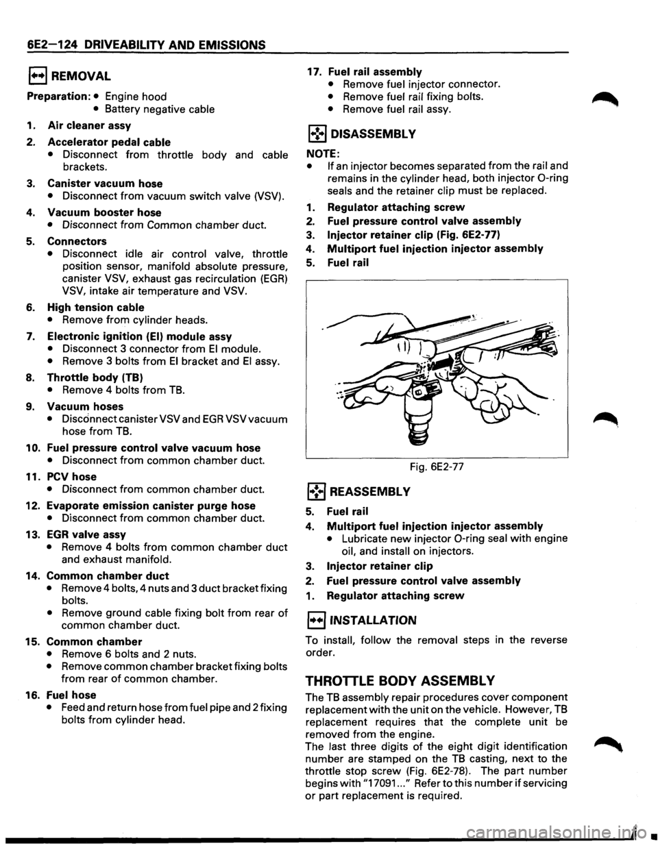
3. Injector retainer clip (Fig. 6E2-77)
4.
Multipart fuel injection injector assembly
5. Fuel rail
Fig. 6E2-77
l•! .. j REASSEMBL V
5. Fuel rail
4. Multipart fuel injection injector assembly
• Lubricate new injector 0-ring seal with engine
oil, and
install on injectors.
3.
Injector retainer clip
2. Fuel pressure control valve assembly
1. Regulator attaching screw
l·u·jiNSTALLATION
To install, follow the removal steps in the reverse
order.
THROTTLE BODY ASSEMBL V
The TB assembly repair procedures cover component
replacement
with the unit on the vehicle. However, TB
replacement requires that the complete unit be
removed from the engine.
The last three digits
of the eight digit identification
number are stamped on the
TB casting, next to the
throttle stop screw (Fig. 6E2-78). The part number
begins
with "17091 ... " Refer to this number if servicing
or part replacement is required.
•
Page 823 of 1928
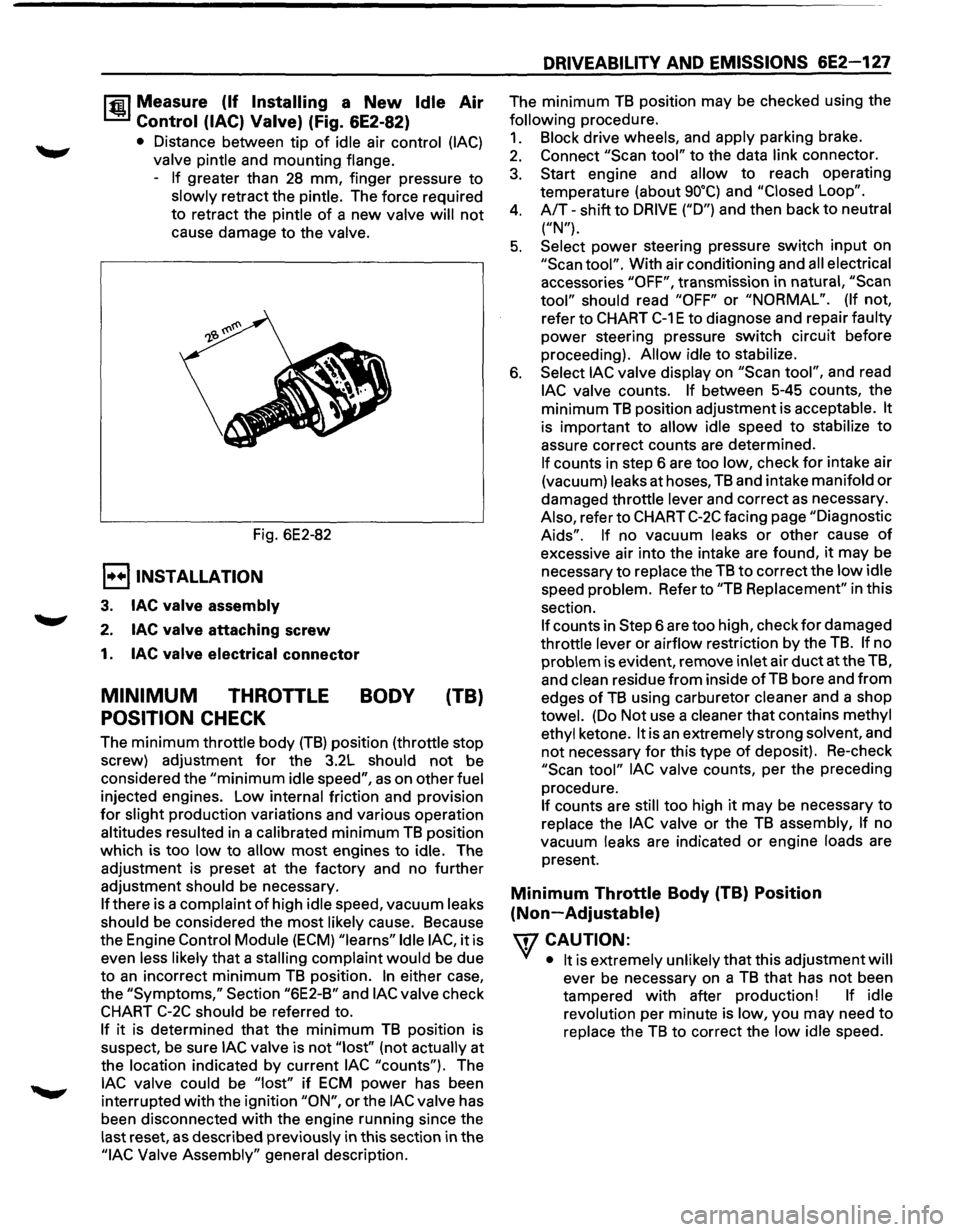
1~1 Measure (If Installing a New Idle Air
Control (lAC) Valve) (Fig. 6E2-82)
• Distance between tip of idle air control (lAC)
valve pintle and mounting flange.
-
If greater than 28 mm, finger pressure to
slowly retract the pintle. The force required
to retract the pintle
of a new valve will not
cause damage to the valve.
Fig. 6E2-82
E) INSTALLATION
3. lAC valve assembly
2. lAC valve attaching screw
1. lAC valve electrical connector
MINIMUM THROTTLE BODY (TB)
POSITION CHECK
The minimum throttle body (TB) position (throttle stop
screw) adjustment
for the 3.2L should not be
considered the
"minimum idle speed", as on other fuel
injected engines. Low internal friction and provision
for slight production variations and various operation
altitudes resulted in a calibrated
minimum TB position
which is too
low to allow most engines to idle. The
adjustment is preset at the factory and no further
adjustment should be necessary.
If there is a complaint of high idle speed, vacuum leaks
should be considered the
most likely cause. Because
the Engine
Control Module (ECM) "learns" Idle lAC, it is
even less likely
that a stalling complaint would be due
to
an incorrect minimum TB position. In either case,
the
"Symptoms," Section "6E2-B" and lAC valve check
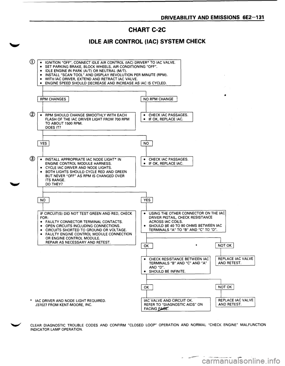
CHART C-2C should be referred to.
If it is determined that the minimum TB position is
suspect,
be sure lAC valve is not "lost'' (not actually at
the location indicated by current
lAC "counts"). The
lAC valve could be "lost" if ECM power has been
interrupted
with the ignition "ON", or the lAC valve has
been disconnected
with the engine running since the
last reset,
as described previously in this section in the
"lAC Valve Assembly" general description.
DRIVEABILITY AND EMISSIONS 6E2-127
The minimum TB position may be checked using the
following procedure.
1. Block drive wheels, and apply parking brake.
2. Connect "Scan tool" to the data link connector.
3. Start engine and allow to reach operating
temperature (about
go•q and "Closed Loop".
4. A/T-shift to DRIVE ("D") and then back to neutral
("N").
5. Select power steering pressure switch input on
"Scan tool". With air conditioning and all electrical
accessories
"OFF", transmission in natural, "Scan
tool" should read "OFF" or "NORMAL". (If not,
refer to
CHART C-1 E to diagnose and repair faulty
power steering pressure switch circuit before
proceeding).
Allow idle to stabilize.
6. Select lAC valve display on "Scan tool", and read
lAC valve counts. If between 5-45 counts, the
minimum
TB position adjustment is acceptable. It
is important to allow idle speed to stabilize to
assure correct counts are determined.
If counts in step 6 are too low, check for intake air
(vacuum) leaks at hoses,
TB and intake manifold or
damaged throttle lever and correct as necessary.
Also, refer to
CHART C-2C facing page "Diagnostic
Aids". If no vacuum leaks or other cause of
excessive air into the intake are found, it may be
necessary
to replace the TB to correct the low idle
speed problem. Refer to
"TB Replacement" in this
section.
If counts in Step 6 are too high, check for damaged
throttle lever or airflow restriction by the
TB. If no
problem is evident, remove inlet air
duct at the TB,
and
clean residue from inside of TB bore and from
edges of TB using carburetor cleaner and a shop
towel. (Do Not use a cleaner that contains methyl
ethyl ketone.
It is an extremely strong solvent, and
not necessary for this type of deposit). Re-check
"Scan tool" lAC valve counts, per the preceding
procedure.
If counts are still too high it may be necessary to
replace the
lAC valve or the TB assembly, If no
vacuum leaks are indicated
or engine loads are
present.
Minimum Throttle Body (TB) Position
(Non-Adjustable)
\fl CAUTION:
VI • It is extremely unlikely that this adjustment will
ever be necessary on a TB that has not been
tampered
with after production! If idle
revolution per minute is low, you may need
to
replace the TB to correct the low idle speed.
Page 824 of 1928
6E2-128 DRIVEABILITY AND EMISSIONS
CHART C-2A
INJECTOR BALANCE TEST
The injector balance tester is a tool used to turn the injector on for a precise amount of time, thus spraying a
measured
amount of fuel into the manifold. This causes a drop in fuel rail pressure that we can record and
compare between each injector.
All injectors should have the same amount of pressure drop (± 10 kPa). Any
injector with a pressure drop that is 10 kPa (or more) greater or less than the average drop of the other injectors
should be considered faulty and replaced.
NOTE: It will be necessary to remove the intake plenum to perform this procedure. Refer to intake plenum
remove procedure in this section. It will also be necessary to install the Intake Manifold Diagnostic Plate J
39185 to enable the engine to be run with the plenum removed. Refer to Chart A-8 in Section "6E2-A" of
this service manual.
STEP 1
Engine "cool down" period (10 minutes) is necessary to avoid irregular readings due to "Hot Soak" fuel boiling.
With ignition "OFF" connect fuel gauge J 347301 or equivalent to fuel pressure tap. Wrap a shop towel around
fitting
while connecting gage to avoid fuel spillage. Refer to Chart A-7 in Section 6E2-A, Page 1 of 3.
Disconnect harness connectors at all injectors, and connect injector tester J 34730-3, or equivalent, to one injector.
Follow manufacturers instructions for use of adaptor harness. Ignition must be "OFF" at least 10 seconds to
complete engine control module shutdown cycle. Fuel pump should run about 2 seconds after ignition is turned
"ON". At this point, insert clear tubing attached to vent valve into a operation. Repeat this step until all air is bled
from gauge.
STEP 2
Turn ignition "OFF" for 10 seconds and then "ON" again to get fuel pressure to its maximum. Record this initial
pressure reading. Energize tester one time and note pressure drop at its lowest point (Disregard any slight
pressure increase after drop hits low point). By subtracting this second pressure reading from the initial pressure, ~
we have the actual amount of injector pressure drop.
STEP 3
Repeat step 2 on each injector and compare the amount of drop. Usually, good injectors will have virtually the
same drop. Retest any injector
that has a pressure difference of 10 kPa, either more or less than the average of the
other injectors on the engine.
Replace any injector that also fails the retest. If the pressure drop of all injectors is
within 10 kPa of this average, the injectors appear to be following properly.
Reconnect them and review "Symptoms", Section "6E3-B".
NOTE: The entire test should NOT be repeated more than once without running the engine to prevent flooding.
(This includes any retest on faulty injectors). To run the engine with the intake plenum removed use the
Intake Manifold Diagnostic Plate.
•
Page 825 of 1928
DRIVEABILITY AND EMISSIONS 6E2-129
CHART C-2A
INJECTOR BALANCE TEST
NOTE: The entire test should NOT be repeated more than once without running the engine to prevent flooding.
(This includes any retest on faulty injectors).
The
fuel pressure test in Section "A" Chart A-7, should be completed prior to this test.
Step 1. If engine is at operating temperature, allow a 10 minute "cool down" period then connect fuel pressure
gauge and injector tester.
1. Ignition "OFF".
2. Connect fuel pressure gauge and injector tester.
3. Ignition "ON".
4. Bleed off air gauge. Repeat until all air is bled from gauge.
Step 2. Run test:
Step 3.
1. Ignition "OFF" for 1 0 seconds.
2. Ignition "ON". Record gauge pressure. (Pressure must hold steady, if not see the Fuel System
diagnosis, Chart A-7, in Section "A").
3. Turn injector on, by depressing button on injector tester, and note pressure at the instant the gauge
needle stops.
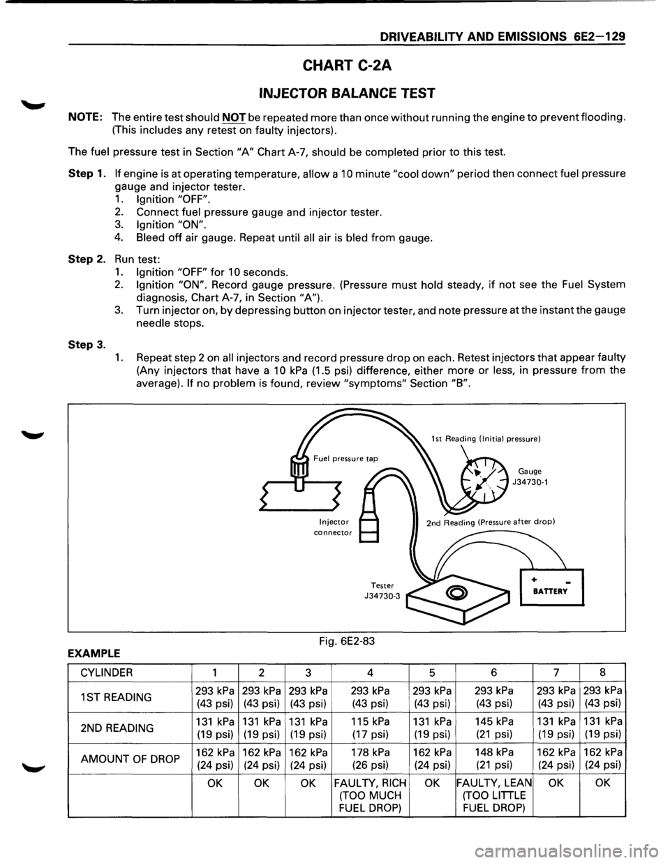
1. Repeat step 2 on all injectors and record pressure drop on each. Retest injectors that appear faulty
(Any injectors that have a 10 kPa (1.5 psi) difference, either more or less, in pressure from the
average).
If no problem is found, review "symptoms" Section "8".
Injector connector
Tester J34730-3
Fig. 6E2-83
Gauge J34730-1
BATTERY
EXAMPLE
CYLINDER 1 2
3 4
5 6 7 8
1ST
READING 293 kPa 293 kPa 293 kPa 293 kPa 293 kPa 293 kPa 293 kPa 293 kPa
(43 psi) (43 psi) (43 psi) (43 psi) (43 psi) (43 psi) (43 psi) (43 psi)
2ND
READING 131 kPa 131 kPa 131 kPa 115 kPa 131 kPa 145 kPa 131 kPa 131 kPa
(19 psi) (19 psi) (19 psi) (17 psi) (19 psi) (21 psi) (19 psi) (19
psi)
AMOUNT
OF DROP 162 kPa 162 kPa 162 kPa 178 kPa 162 kPa 148 kPa 162 kPa 162 kPa
(24 psi) (24 psi)
(24 psi) (26
psi) (24 psi) (21 psi) (24 psi) (24 psi)
OK OK OK FAULTY, RICH OK FAULTY, LEAN OK OK
(TOO MUCH (TOO LITTLE
FUEL DROP) FUEL DROP)
Page 827 of 1928
DRIVEABILITY AND EMISSIONS 6E2-131
CHART C-2C
IDLE AIR CONTROL (lAC) SYSTEM CHECK
CD • IGNITION "OFF", CONNECT IDLE AIR CONTROL (lAC) DRIVER* TO lAC VALVE. • SET PARKING BRAKE, BLOCK WHEELS, AIR CONDITIONING "OFF".
• IDLE ENGINE IN PARK (A/T) OR NEUTRAL (MIT). • INSTALL "SCAN TOOL" AND DISPLAY REVOLUTION PER MINUTE (RPM). • WITH lAC DRIVER, EXTEND AND RETRACT lAC VALVE. • ENGINE SPEED SHOULD DECREASE AND INCREASE AS lAC IS CYCLED.
I
1 I • RPM CHANGES I NO RPM CHANGE I
I I • RPM SHOULD CHANGE SMOOTHLY
WITH EACH • CHECK lAC PASSAGES.
I FLASH OF THE lAC DRIVER LIGHT FROM 700 RPM • IF OK, REPLACE lAC.
TO ABOUT 1500 RPM. DOES IT?
I
~ cf
• INSTALL APPROPRIATE lAC NODE LIGHT* IN • CHECK lAC PASSAGES.
l ENGINE CONTROL MODULE HARNESS. • IF OK, REPLACE lAC. ®
• CYCLE lAC
DRIVER AND NODE LIGHTS.
• BOTH LIGHTS SHOULD CYCLE RED AND GREEN BUT NEVER "OFF" AS RPM IS CHANGED OVER
ITS RANGE. DO THEY?
I
cf ~ IF CIRCUIT(S) DID NOT TEST GREEN AND RED, CHECK •
USING THE OTHER CONNECTOR ON THE lAC
FOR: DRIVER
PIGTAIL, CHECK RESISTANCE
•
FAULTY CONNECTOR TERMINAL CONTACTS. ACROSS
lAC COILS.
• OPEN CIRCUITS INCLUDING CONNECTIONS. •
SHOULD BE 40 TO 80 OHMS BETWEEN lAC
• CIRCUITS SHORTED TO GROUND OR VOLTAGE. TERMINALS "A" TO "B" AND "C" TO "D".
• FAULTY ENGINE CONTROL MODULE CONNECTION I OR ENGINE CONTROL MODULE.
~
l REPAIR AS NECESSARY AND RETEST. l NOT OK I .
_l
• CHECK RESISTANCE BETWEEN lAC I REPLACE lAC VALVE I TERMINALS "B" AND "C" AND "A" AND RETEST. AND "D". • SHOULD BE INFINITE.
I
~
l
I NOT OK I
]
AC DRIVER AND NODE LIGHT REQUIRED. * I J lAC VALVE AND CIRCUIT OK. I REPLACE lAC VALVE J 37027 FROM KENT-MOORE, INC. REFER TO "DIAGNOSTIC AIDS" ON AND RETEST. FACING~
~ CLEAR DIAGNOSTIC TROUBLE CODES AND CONFIRM "CLOSED LOOP" OPERATION AND NORMAL "CHECK ENGINE" MALFUNCTION
INDICATOR LAMP OPERATION.
------
Page 828 of 1928
6E2-132 DRIVEABILITV AND EMISSIONS
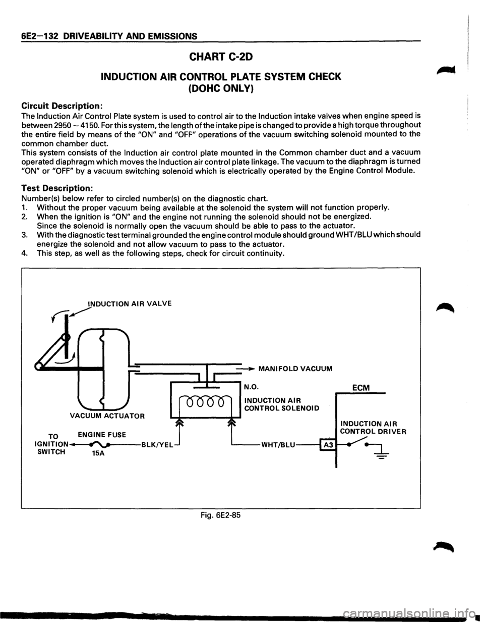
CHART C-20
INDUCTION AIR CONTROL PLATE SYSTEM CHECK
(DOHC ONLY)
Circuit Description:
The Induction Air Control Plate system is used to control air to the Induction intake valves when engine speed is
between
2950-4150. For this system, the length of the intake pipe is changed to provide a high torque throughout
the entire field by means
of the "ON" and "OFF" operations of the vacuum switching solenoid mounted to the
common chamber duct.
This system consists
of the Induction air control plate mounted in the Common chamber duct and a vacuum
operated diaphragm which moves the
Induction air control plate linkage. The vacuum to the diaphragm is turned
"ON" or "OFF" by a vacuum switching solenoid which is electrically operated by the Engine Control Module.
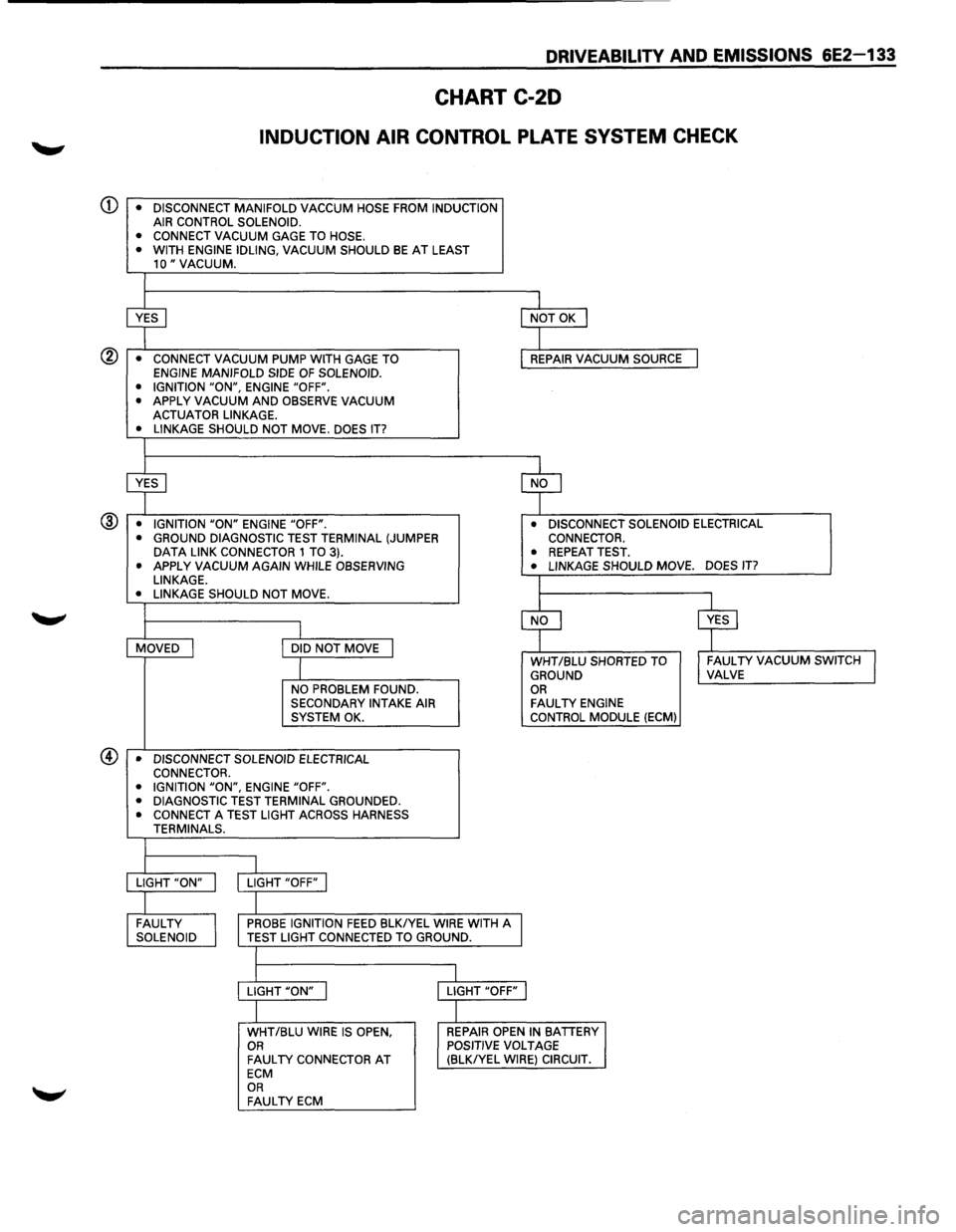
Test Description:
Number(s) below refer to circled number(s) on the diagnostic chart.
1. Without the proper vacuum being available at the solenoid the system will not function properly.
2. When the ignition is "ON" and the engine not running the solenoid should not be energized.
Since the solenoid is normally open the vacuum should
be able to pass to the actuator.
3. With the diagnostic test terminal grounded the engine control module should ground WHT /BLU which should
energize the solenoid and
not allow vacuum to pass to the actuator.
4. This step, as well as the following steps, check for circuit continuity.
INDUCTION AIR VALVE
fi~
__ __...._ MANIFOLDVACUUM
r-=~=-~ N.O.
VACUUM ACTUATOR
TO IGNITION IIi SWITCH ENGINE
FUSE
fl""'v---BLK/YEL
15A
INDUCTION AIR CONTROL
SOLENOID
'----WHT/BLU---1
Fig. 6E2-85 ECM
INDUCTION AIR CONTROL DRIVER
•
Page 829 of 1928
DRIVEABILITV AND EMISSIONS 6E2-133
CHART C-20
INDUCTION AIR CONTROL PLATE SYSTEM CHECK
• CONNECT VACUUM
GAGE TO HOSE.
• WITH ENGINE IDLING, VACUUM SHOULD BE AT LEAST 10" VACUUM.
~
I NOT OK I
I • CONNECT VACUUM PUMP WITH GAGE TO REPAIR VACUUM SOURCE I ENGINE MANIFOLD SIDE OF SOLENOID.
• IGNITION "ON", ENGINE "OFF".
• APPLY VACUUM AND OBSERVE VACUUM ACTUATOR LINKAGE.
• LINKAGE SHOULD NOT MOVE. DOES IT?
~ ~ • IGNITION "ON" ENGINE "OFF". • DISCONNECT SOLENOID ELECTRICAL ® • GROUND DIAGNOSTIC TEST TERMINAL (JUMPER CONNECTOR. DATA LINK CONNECTOR 1 TO 3). • REPEAT TEST. • APPLY VACUUM AGAIN WHILE OBSERVING • LINKAGE SHOULD MOVE. DOES IT?
LINKAGE.
L • LINKAGE SHOULD NOT MOVE.
~ ~ I MOVED I DID NOT MOVE I
I WHT /BLU SHORTED TO I FAULTY VACUUM SWITCH I GROUND VALVE
NO PROBLEM FOUND. OR SECONDARY INTAKE AIR FAUL TV ENGINE SYSTEM OK. CONTROL
MODULE (ECM)
• DISCONNECT SOLENOID ELECTRICAL
CONNECTOR.
• IGNITION
"ON", ENGINE "OFF".
• DIAGNOSTIC TEST TERMINAL GROUNDED. • CONNECT A TEST LIGHT ACROSS HARNESS
TERMINALS.
I LIGHT "ON" I LIGHT "OFF" I
I FAULTY
I
PROBE IGNITION FEED BLKIYEL WIRE WITH A SOLENOID TEST LIGHT CONNECTED TO GROUND.
I
l
LIGHT "ON" I LIGHT "OFF" j
I WHT/BLU WIRE IS OPEN, REPAIR OPEN IN BATTERY OR POSITIVE VOLTAGE FAUL TV CONNECTOR AT (BLKIYEL WIRE) CIRCUIT. ECM OR FAULTY ECM
Page 832 of 1928
6E2-136 DRIVEABILITY AND EMISSIONS
CHART C-3
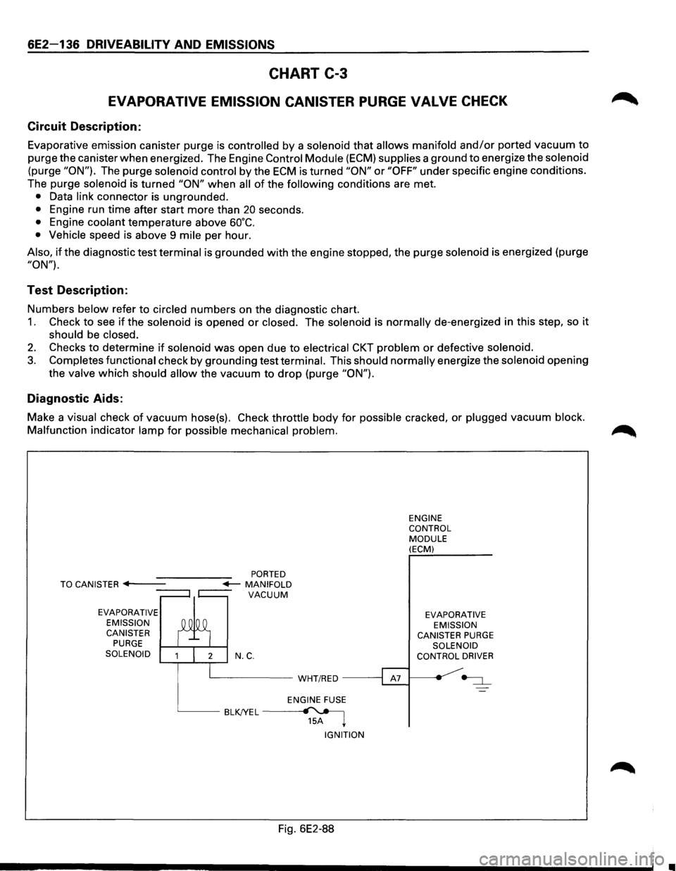
EVAPORATIVE EMISSION CANISTER PURGE VALVE CHECK
Circuit Description:
Evaporative emission canister purge is controlled by a solenoid that allows manifold and/or ported vacuum to
purge the canister when energized. The Engine Control Module (ECM) supplies a ground to energize the solenoid
(purge "ON"). The purge solenoid control by the ECM is turned "ON" or "OFF" under specific engine conditions.
The purge
solenoid is turned "ON" when all of the following conditions are met.
• Data link connector is ungrounded.
• Engine run time after start more than 20 seconds.
• Engine coolant temperature above 60°C.
• Vehicle speed is above 9 mile per hour.
Also, if the diagnostic test terminal is grounded with the engine stopped, the purge solenoid is energized (purge
"ON").
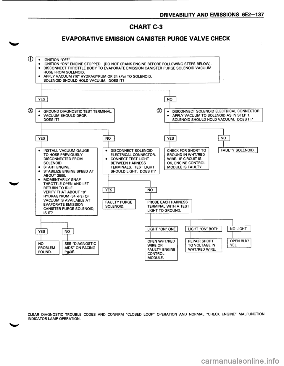
Test Description:
Numbers below refer to circled numbers on the diagnostic chart.
1. Check to see if the solenoid is opened or closed. The solenoid is normally de-energized in this step, so it
should be closed.
2. Checks to determine if solenoid was open due to electrical CKT problem or defective solenoid.
3. Completes functional check by grounding test terminal. This should normally energize the solenoid opening
the
valve which should allow the vacuum to drop (purge "ON").
Diagnostic Aids:
Make a visual check of vacuum hose(s). Check throttle body for possible cracked, or plugged vacuum block.
Malfunction
indicator lamp for possible mechanical problem.
EVAPORATIVE
EMISSION CANISTER
PURGE SOLENOID N.C.
L__ _____ WHT/RED -----;
ENGINE FUSE
BLKJYEL~ 15A ~
IGNITION
Fig. 6E2-88
ENGINE
CONTROL
MODULE (ECM)
EVAPORATIVE EMISSION
CANISTER
PURGE SOLENOID
CONTROL DRIVER
•
Page 833 of 1928
DRIVEABILITV AND EMISSIONS 6E2-137
CHART C-3
EVAPORATIVE EMISSION CANISTER PURGE VALVE CHECK
Q) • IGNITION "OFF"
• IGNITION "ON" ENGINE STOPPED. (DO NOT CRANK ENGINE BEFORE FOLLOWING STEPS BELOW).
• DISCONNECT THROTTLE BODY TO EVAPORATE EMISSION CANISTER PURGE SOLENOID VACUUM
HOSE FROM SOLENOID.
•
APPLY VACUUM (10" HYDRAGYRUM OR 34 kPa) TO SOLENOID.
SOLENOID SHOULD HOLD VACUUM. DOES IT?
~ $
• GROUND DIAGNOSTIC TEST TERMINAL. @ • DISCONNECT SOLENOID ELECTRICAL CONNECTOR. ® • VACUUM SHOULD DROP. • APPLY VACUUM TO
SOLENOID AS IN STEP 1. DOES IT? SOLENOID
SHOULD HOLD VACUUM. DOES IT?
I
$ $ $ $
• INSTALL VACUUM GAUGE • DISCONNECT SOLENOID CHECK FOR SHORT TO I FAULTY SOLENOID. J TO HOSE PREVIOUSLY ELECTRICAL CONNECTOR. BROUND IN WHT
/RED DISCONNECTED FROM
• CONNECT TEST LIGHT WIRE. IF CIRCUIT IS SOLENOID. BETWEEN HARNESS
OK,
ENGINE CONTROL
• START ENGINE. TERMINALS. TEST LIGHT MODULE IS FAULTY. •
STABILIZE ENGINE SPEED AT SHOULD LIGHT. DOES IT?
ABOUT 2500.
• MOMENTARILY SNAP
THROTTLE OPEN AND LET
$
RETURN TO IDLE.
~
VERIFY THAT ABOUT 10" HYDRAGYRUM (34 kPa) OF VACUUM IS AVAILABLE AT FAULTY PURGE I PROBE EACH HARNESS
EVAPORATE EMISSION
SOLENOID. TERMINAL WITH A TEST
CANISTER PURGE SOLENOID, LIGHT TO GROUND.
IS IT?
I I
$
$
LIGHT "ON" ONE LIGHT
"ON" BOTH I NO LIGHT J
I I
OPEN WHT/RED REPAIR SHORT I OPEN BLK/ I NO SEE "DIAGNOSTIC
WIRE OR TO VOLTAGE IN VEL PROBLEM ~~.ON FACING FAULTY ENGINE WHT/RED WIRE.
FOUND. p . CONTROL
MODULE.
CLEAR DIAGNOSTIC TROUBLE CODES AND CONFIRM "CLOSED LOOP" OPERATION AND NORMAL "CHECK ENGINE" MALFUNCTION
INDICATOR LAMP OPERATION.
Page 834 of 1928
6E2-138 DRIVEABILITY AND EMISSIONS
SECTION C4
ELECTRONIC IGNITION (EI) SYSTEM/IGNITION CONTROL (IC)
CONTENTS
General Description . . . . . . . . . . . . . . . . . . . . . 6E2-138
Purpose
............................ 6E2-138
Operation
........................... 6E2-138
Results of Incorrect Operation . . . . . . . . . . . 6E2-139
How diagnostic trouble code (DTC) 42 is
Determined ........................ 6E2-139
Diagnosis. . . . . . . . . . . . . . . ............. 6E2-139
Diagnostic
trouble code (DTC) 12 . . . . . . . . . 6E2-139
On-Vechicle Service . .
. . . . . . . . . . . . . . . . . . . 6E2-139
Electronic Ignition (EI) Assembly .......... 6E2-139
Crankshaft Position (CKP) Sensor ......... 6E2-140
Ignition Coil
.......................... 6E2-140
Ignition Control
Module (ICM) ............ 6E2-140
Ignition
Timing ....................... 6E2-140
Chart
C-4D-1 Electronic Ignition (EI) misfire
at
Idle .............................. 6E2-142
Chart C-4D-2 Electronic Ignition (EI) misfire
Under Load .......................... 6E2-144
GENERAL DESCRIPTION
PURPOSE
The Electronic Ignition (EI) system controls fuel
combustion by providing a spark to ignite the
compressed
air/fuel mixture at the correct time. To
provide improved engine performance,
fuel economy,
and
control of exhaust emissions, the Engine Control
Module
(ECM) controls spark advance timing with the
Ignition Control (IC) system.
OPERATION
The "EI" is a "waste spark" system in which 2 plugs are
fired
simultaneously from one coil. The spark plugs are
paired
to a coil, so that when both fire, one cylinder is
on the compression stroke and the other is on exhaust.
There is
Iitie resistance across the plug gap on the
exhaust stroke, so the
plug requires very little voltage
to fire, thereby providing the other plug (compression)
with maximum available voltage.
The system uses a magnetic Crankshaft Position (CKP)
sensor which protrudes into the block, within
approximately .050" of the crankshaft reluctor. The
reluctor is a special wheel cast on the crankshaft that
has seven machined
slots, six of which are equally
spaced 60° apart). The seventh slot is spaced 1 oo from
one
of the other slots. As the reluctor rotates with the
crankshaft, the
slots change the magnetic field of the
sensor, causing
an induced voltage pulse.
By counting the time between pulses, the Ignition
Control Module (ICM)
can recognize the pulse of the
seventh
slot (sync pulse). Based on this sync pulse, the
module sends the reference signal to the ECM to
calculate CKP (used to fire coils in correct sequence)
and engine speed.
To
properly control timing, the ECM relies on the
following information:
• Engine load (manifold absolute pressure or
vacuum).
• Atmospheric (barometric) pressure.
• Engine temperature.
• Intake air temperature.
• CKP
• Engine speed (revolution per minute).
The ignition
control system consisits of the "EI"
assembly (coils, module,
and CKP sensor), ECM and
connecting wires. These circuits
perform the following
functions:
• "EI" reference
The CKP sensor sends a signal to the ICM which
generates a reference
pulse which is sent to the
ECM. The ECM uses this signal to calculate CKP
and engine speed (also used to trigger the
injector).
• Reference ground (GND)
This wire is GNd through the module and makes
sure the GNd circuit has no
voltage drop between
the
ICM and the ECM, which if open, could affect
performance.
• Bypass
At about 400 revolution per minute, the ECM
applies 5 volts to this circuit to switch spark timing
control from the ICM to the ECM. An open or
grounded bypass circuit
will set a diagnostic
trouble code 42 and the engine will run at base
timing,
plus a small amount of advance built into
the
ICM.
• IGNITION CONTROL (IC)
The ECM uses this circuit (when bypass voltage is
applied) to trigger the "EI" module. The ECM uses
the
CKP to base its calculation of the amount of
spark advance needed under present engine
conditions.
•