ISUZU TROOPER 1995 Workshop Manual
Manufacturer: ISUZU, Model Year: 1995, Model line: TROOPER, Model: ISUZU TROOPER 1995Pages: 1928
Page 1511 of 1928
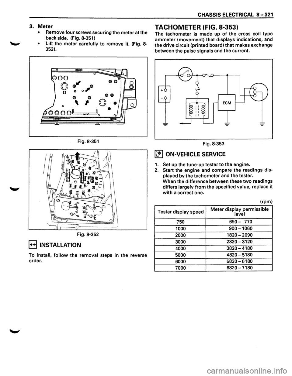
3. Meter
• Remove four screws securing the meter at the
back side. (Fig.
8-351)
• Lift the meter carefully to remove it. (Fig. 8-
352).
0
q;J"' 0
0 0 0,
0 0
0 I
Fig. 8-351
Fig. 8-352
E) INSTALLATION
00
0
To install, follow the removal steps in the reverse
order.
CHASSIS ELECTRICAL 8-321
TACHOMETER (FIG. 8-353)
The tachometer is made up of the cross coil type
ammeter (movement) that displays indications, and
the drive circuit (printed board)
that makes exchange
between the
pulse signals and the current.
Fig.
8-353
(1!1 ON-VEHICLE SERVICE
1. Set up the tune-up tester to the engine.
2. Start the engine and compare the readings dis
played by the tachometer and the tester.
When the difference between these
two readings
differs
largely from the specified value, replace it
with a correct one.
(rpm)
Tester
display speed Meter
display permissible level
750 690-770
1000
900-1060
2000 1820-2090
3000 2820-3120
4000 3820-4180
5000 4820-5180
6000 5820-6180
7000 6820-7180
Page 1512 of 1928
8 -322 CHASSIS ELECTRICAL
NOTE: Since
the meter display permissible lev
els
above are specifications solely for
the meter, they are to be used as refer
ence values when conducting on-vehicle
inspection.
p
IGN GND
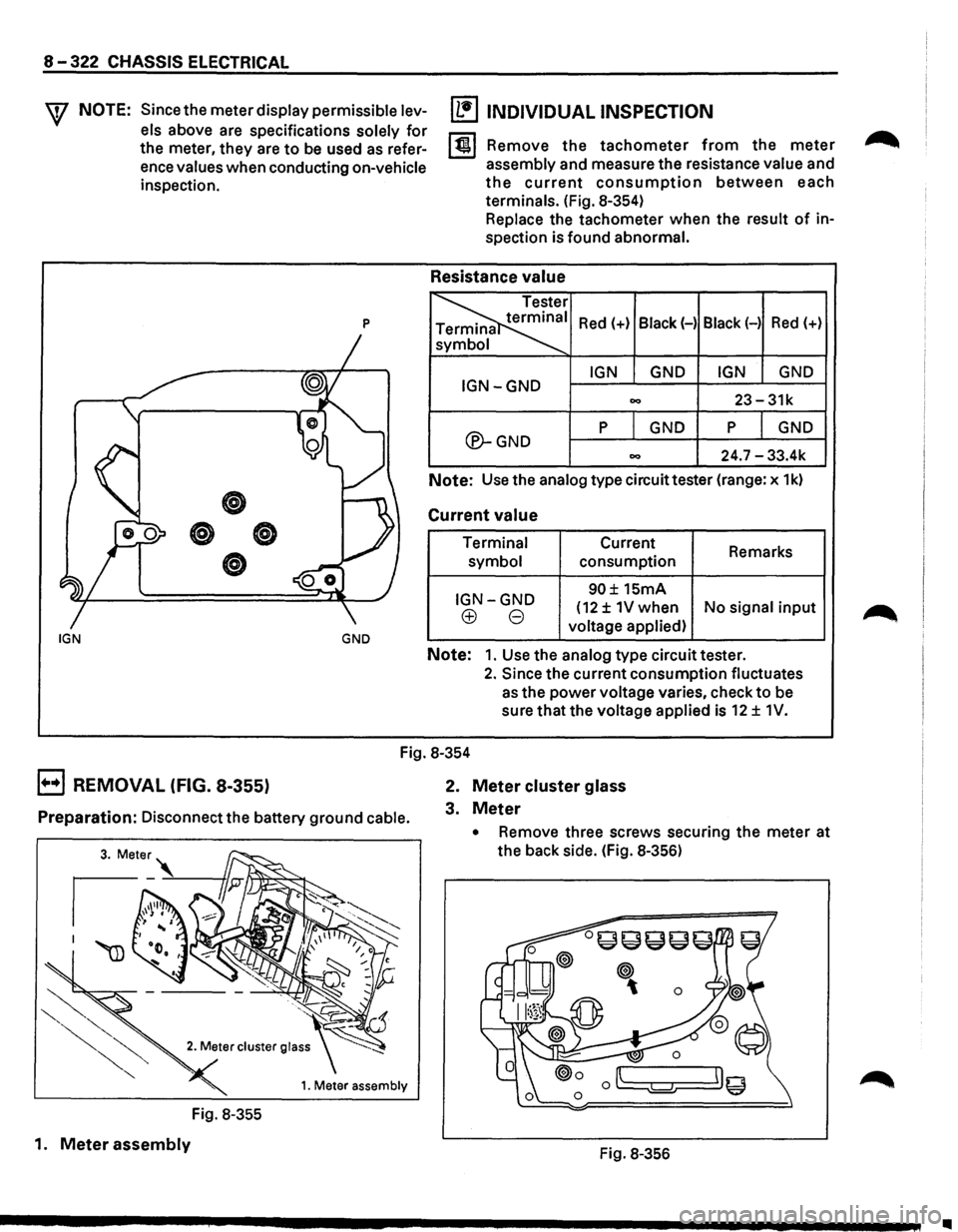
[b!J INDIVIDUAL INSPECTION
I tii~,l Remove the tachometer from the meter
assembly and measure the resistance value and
the current consumption between each
terminals. (Fig. 8-354)
Replace the tachometer when the result of in
spection is found abnormal.
Resistance value
Red(+) Black(-) Black(-) Red(+)
IGN GND IGN GND IGN-GND 00 23-31k
®-GND
p GND p GND
00 24.7 -33.4k
Note: Use the analog type
circuittester (range: x 1k)
Current value
Terminal
symbol
IGN-GND
(±) 8
Current
consumption
90± 15mA Remarks
(12 ± 1V when
No signal input
voltage applied)
Note: 1. Use the analog type circuit tester.
2. Since the current consumption fluctuates
as the power voltage varies, check to be
sure that the
voltage applied is 12 ± 1V.
Fig. 8-354
E) REMOVAL (FIG. 8-355)
Preparation: Disconnect the battery ground cable.
1. Meter assembly
Fig. 8-355
1.
Meter assembly
2. Meter cluster glass
3. Meter
• Remove three screws securing the meter at
the back side. (Fig. 8-356)
Fig. 8-356
•
Page 1513 of 1928
B INSTALLATION
To install, follow the removal steps in the reverse
order.
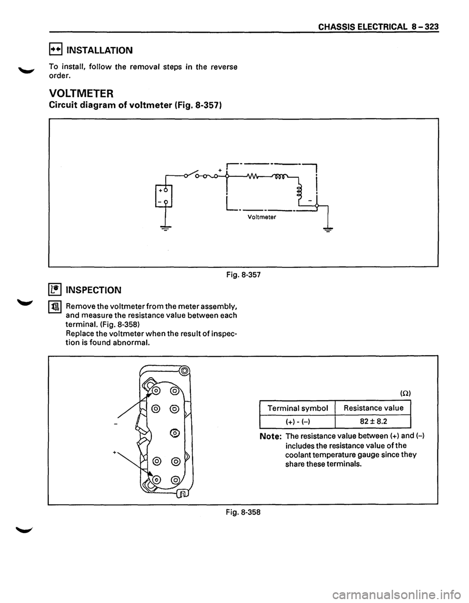
VOLTMETER
Circuit diagram of voltmeter (Fig. 8-357)
CHASSIS ELECTRICAL 8-323
Voltmeter
Fig. 8-357
~ INSPECTION
I t!!.l Remove the voltmeter from the meter assembly,
and measure the resistance value between each
terminal. (Fig. 8-358)
Replace the voltmeter when the result of inspec
tion is found
abnormal.
+
(Q)
Terminal symbol Resistance value
(+)-(-) 82 ± 8.2
Note: The resistance value between (+) and H
includes the resistance value ofthe
coolant temperature gauge since they
share these
terminals.
Fig. 8-358
Page 1514 of 1928
8-324 CHASSIS ELECTRICAL
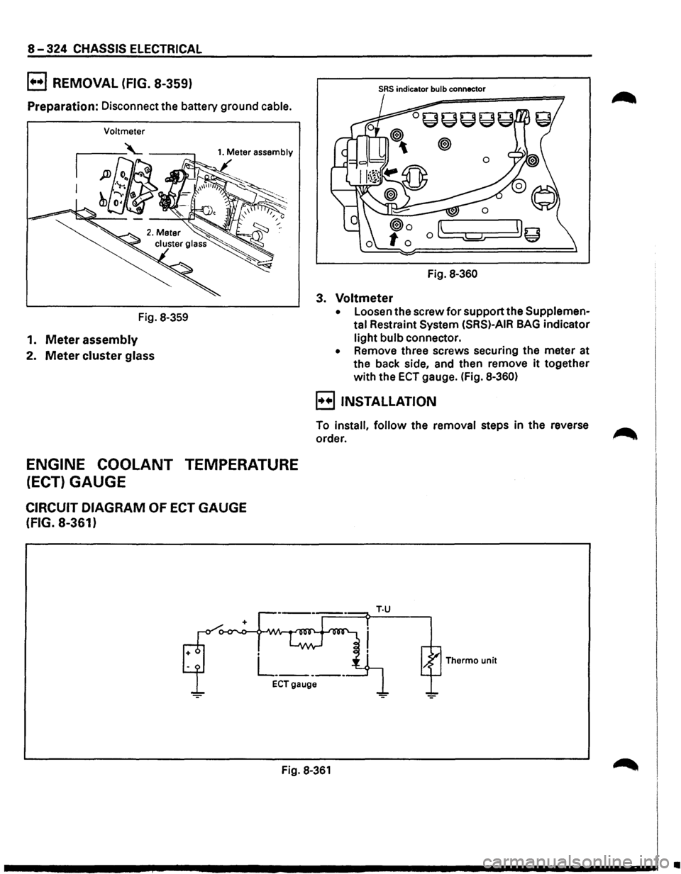
B REMOVAL (FIG. 8-359)
Preparation: Disconnect the battery ground cable.
Voltmeter
Fig. 8-359
1. Meter assembly
2. Meter cluster glass
ENGINE COOLANT TEMPERATURE
(ECT) GAUGE
CIRCUIT DIAGRAM OF ECT GAUGE
(FIG. 8-361)
SRS indicator bulb connector
Fig. 8-360
3. Voltmeter
• Loosen the screw for support the Supplemen
tal
Restraint System (SRS)-AIR BAG indicator
light bulb connector.
• Remove three screws securing the meter at
the back side, and then remove
it together
with the
ECT gauge. (Fig. 8-360)
B INSTALLATION
To install, follow the removal steps in the reverse ....-...
order. ,........
Thermo unit
ECTgauge
Fig. 8-361
•
Page 1515 of 1928
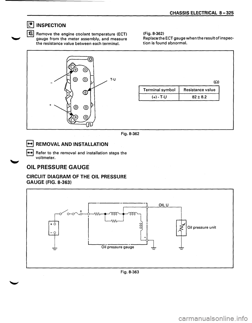
~ INSPECTION
131 Remove the engine coolant temperature (ECT)
gauge from the meter assembly, and measure
the resistance value between each terminal.
T·U
+
Fig. 8-362
E) REMOVAL AND INSTALLATION
1••1 Refer to the removal and installation steps the
voltmeter.
OIL PRESSURE GAUGE
CIRCUIT DIAGRAM OF THE OIL PRESSURE
GAUGE (FIG. 8-363)
CHASSIS ELECTRICAL 8 -325
(Fig. 8-362)
Replace the
ECT gauge when the result of inspec
tion is found abnormal.
(Q)
Terminal symbol Resistance
value
(+)-T·U 82 ± 8.2
OILU
Oil pressure unit
,______ _ __ ___.
Oil pressure gauge
Fig. 8-363
Page 1516 of 1928
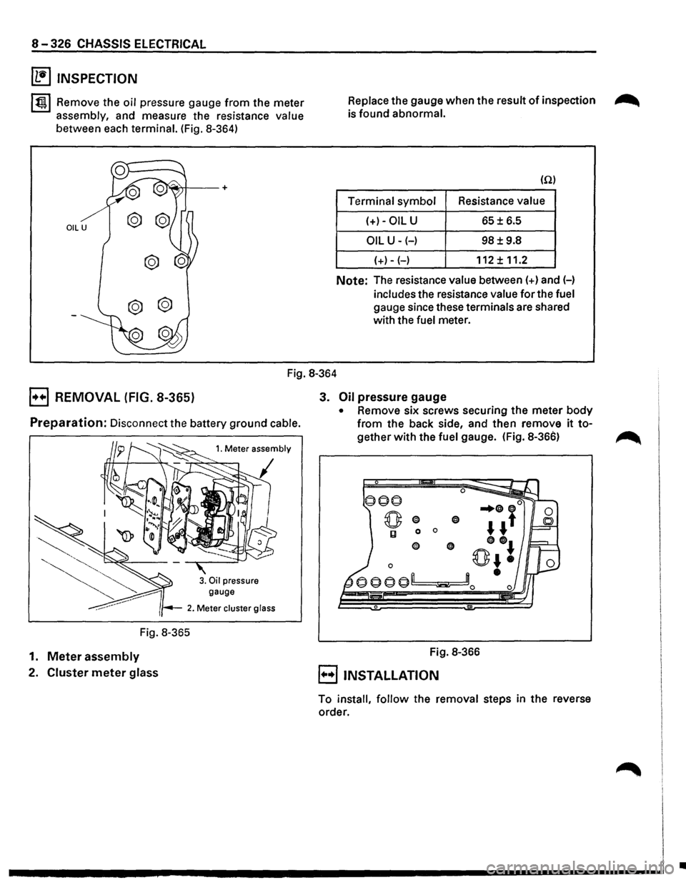
8-326 CHASSIS ELECTRICAL
~ INSPECTION
l~l Remove the oil pressure gauge from the meter
assembly, and measure the resistance value
between each terminal. (Fig. 8-364)
Replace the gauge when the result of inspection ~
is found abnormal.
(Q)
Terminal symbol Resistance value
(+)-OIL U 65± 6.5
OIL U-(-) 98±9.8
{+)-{-) 112± 11.2
Note: The resistance value between {+)and(-)
includes the resistance value for the fuel
gauge since these terminals are shared
with the
fuel meter.
Fig. 8-364
B REMOVAL (FIG. 8-365)
Preparation: Disconnect the battery ground cable.
gauge
2. Meter cluster glass
Fig. 8-365
1.
Meter assembly
2. Cluster meter glass
3. Oil pressure gauge
• Remove six screws securing the meter body
from the back side, and then remove it to
gether with the fuel gauge. (Fig. 8-366)
Fig. 8-366
E) INSTALLATION
To install, follow the removal steps in the reverse
order.
•
Page 1517 of 1928
CHASSIS ELECTRICAL 8 -327
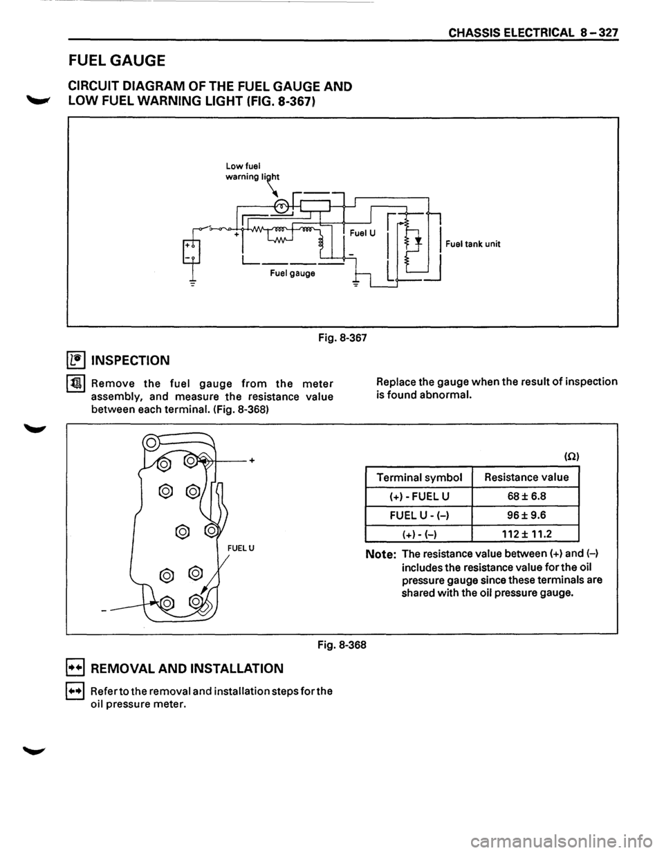
FUEL GAUGE
CIRCUIT DIAGRAM OF THE FUEL GAUGE AND
'--"' LOW FUEL WARNING LIGHT (FIG. 8-367)
Low fuel
Fuel gauge
Fig. 8-367
~ INSPECTION
lt!tl Remove the fuel gauge from the meter
assembly, and measure the resistance value
between each terminal. (Fig. 8-368) Replace
the gauge when the result
of inspection
is found abnormal.
(Q)
Terminal symbol Resistance
value
(+)-FUEL U
68± 6.8
FUEL U-(-) 96± 9.6
(+)- (-)
112 ± 11.2
Note: The resistance value between(+) and H
includes the resistance value
for the oil
pressure gauge since these terminals are
shared with the
oil pressure gauge.
Fig. 8-368
B REMOVAL AND INSTALLATION
1•,.1 Refer to the removal and installation steps for the
oil pressure meter.
Page 1518 of 1928
8-328 CHASSIS ELECTRICAL
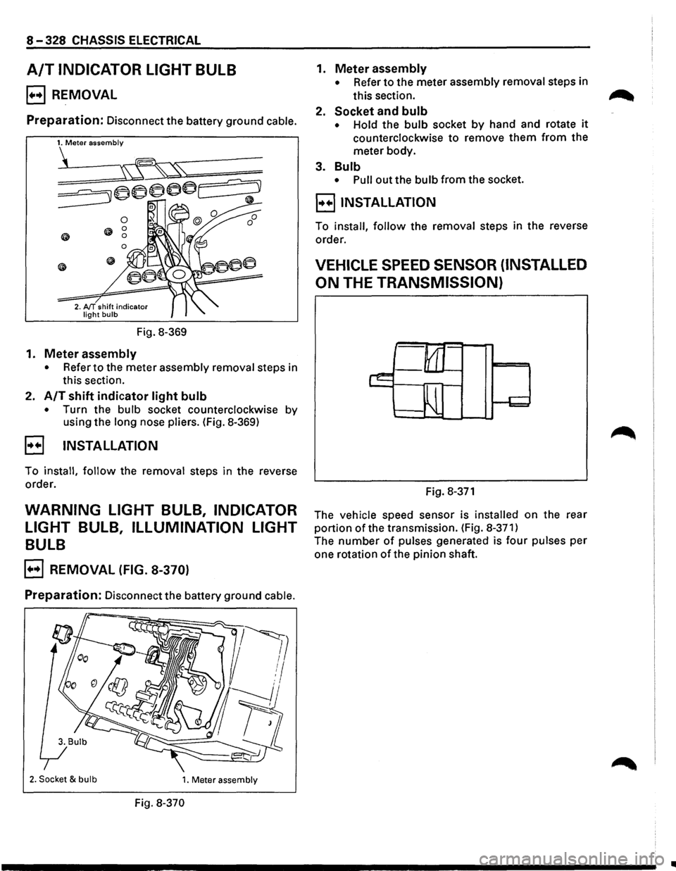
A/T INDICATOR LIGHT BULB
B REMOVAL
Preparation: Disconnect the battery ground cable.
Fig.
8-369
1. Meter assembly
• Refer to the meter assembly removal steps in
this section.
2.
A/T shift indicator light bulb
• Turn the bulb socket counterclockwise by
using the
long nose pliers. (Fig. 8-369)
B INSTALLATION
To install, follow the removal steps in the reverse
order.
WARNING LIGHT BULB, INDICATOR
LIGHT
BULB, ILLUMINATION LIGHT
BULB
B REMOVAL (FIG. 8-370)
Preparation: Disconnect the battery ground cable.
2. Socket & bulb 1. Meter assembly
Fig. 8-370
1. Meter assembly
• Refer to the meter assembly removal steps in
this section.
2.
Socket and bulb
• Hold the bulb socket by hand and rotate it
counterclockwise to remove them from the
meter body.
3.
Bulb
• Pull out the bulb from the socket.
B INSTALLATION
To install, follow the removal steps in the reverse
order.
VEHICLE SPEED SENSOR (INSTALLED
ON
THE TRANSMISSION)
Fig. 8-371
The vehicle speed sensor is installed on the rear
portion of the transmission. (Fig. 8-371)
The number of pulses generated is four pulses per
one rotation
of the pinion shaft.
..
Page 1519 of 1928
![ISUZU TROOPER 1995 Workshop Manual (1!] INSPECTION (FIG. 8-372)
Battery
Fig. 8-372
1. Connect the vehicle speed sensor connector 1
IM-101 to the battery (+)terminal and 2 IM-101 to
the (-)terminal.
2. Connect a resistance of](/img/61/57183/w960_57183-1518.png "ISUZU TROOPER 1995 Workshop Manual (1!] INSPECTION (FIG. 8-372)
Battery
Fig. 8-372
1. Connect the vehicle speed sensor connector 1
IM-101 to the battery (+)terminal and 2 IM-101 to
the (-)terminal.
2. Connect a resistance of")
(1!] INSPECTION (FIG. 8-372)
Battery
Fig. 8-372
1. Connect the vehicle speed sensor connector 1
IM-101 to the battery (+)terminal and 2 IM-101 to
the (-)terminal.
2. Connect a resistance of 1.3k ohm to Sk ohm ( 1/4W
or more) between connectors 1 ~ and 3
IM-101.
W CAUTION: Be extremely careful not to con
nect the battery(+)
terminal to the
connector
3IM-1ol.
This may damage the vehicle
speed sensor.
3. Rotate the shaft of the vehicle speed sensor
1~1 slowly and measure the voltage at both ends
with a digital tester.
The voltage,
with one rotation of shaft,
fluctuates
four times in the following range
:10 to 14V <-> 2Vor less.
Replace the sensor when the resu It of i nspec
tion is found abnormal.
CHASSIS ELECTRICAL 8-329
B REMOVAL (FIG. 8-373)
Preparation: Disconnect the battery ground cable.
1. Vehicle speed sensor
Fig. 8-373
1. Vehicle speed sensor
• Disconnect the connector.
• Remove the vehicle speed sensor body by
rotating it.
Page 1520 of 1928
8-330 CHASSIS ELECTRICAL
B INSTALLATION TRANSMISSION SWITCH
To install, follow the removal steps in the reverse ll•IINSPECTION
order, noting the following points.
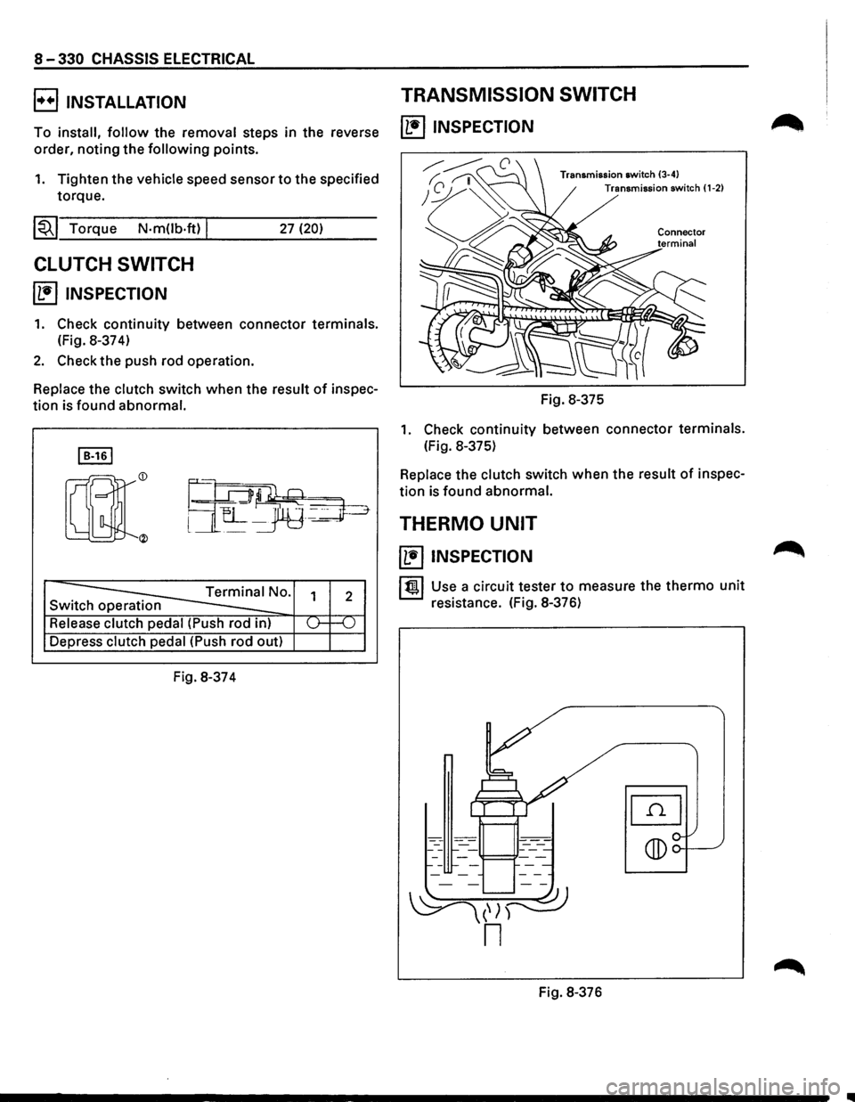
1. Tighten the vehicle speed sensor to the specified
torque. Transmission switch (1-2)
~~~ Torque N·mUb·ft) j
CLUTCH SWITCH
~ INSPECTION
27 (20)
1. Check continuity between connector terminals.
(Fig. 8-37 4)
2. Check the push rod operation.
Replace the clutch switch when the result of inspec-
tion is found abnormal. Fig. 8-375
1. Check continuity between connector terminals.
I B-161 (Fig. 8-375)
Switch operation
Depress
clutch pedal (Push rod out)
Fig. 8-374
Replace the clutch switch when the result of inspec
tion is found abnormal.
THERMO UNIT
~ INSPECTION
11!!.1 Use a circuit tester to measure the thermo unit
resistance. (Fig. 8-376)
Fig. 8-376