ISUZU TROOPER 1995 Workshop Manual
TROOPER 1995
ISUZU
ISUZU
https://www.carmanualsonline.info/img/61/57183/w960_57183-0.png
ISUZU TROOPER 1995 Workshop Manual
Page 1531 of 1928
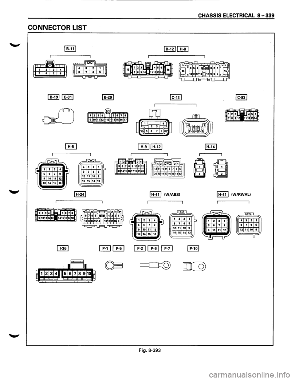
CONNECTOR LIST
12 11 10 16 15 ,. 13
I H-411 (W/ABSI
Fig. 8-393
12 11 10 9 16 15 ,, 13
CHASSIS ELECTRICAL 8-339
I H-411 (W/RWALI
Page 1532 of 1928
8-340 CHASSIS ELECTRICAL
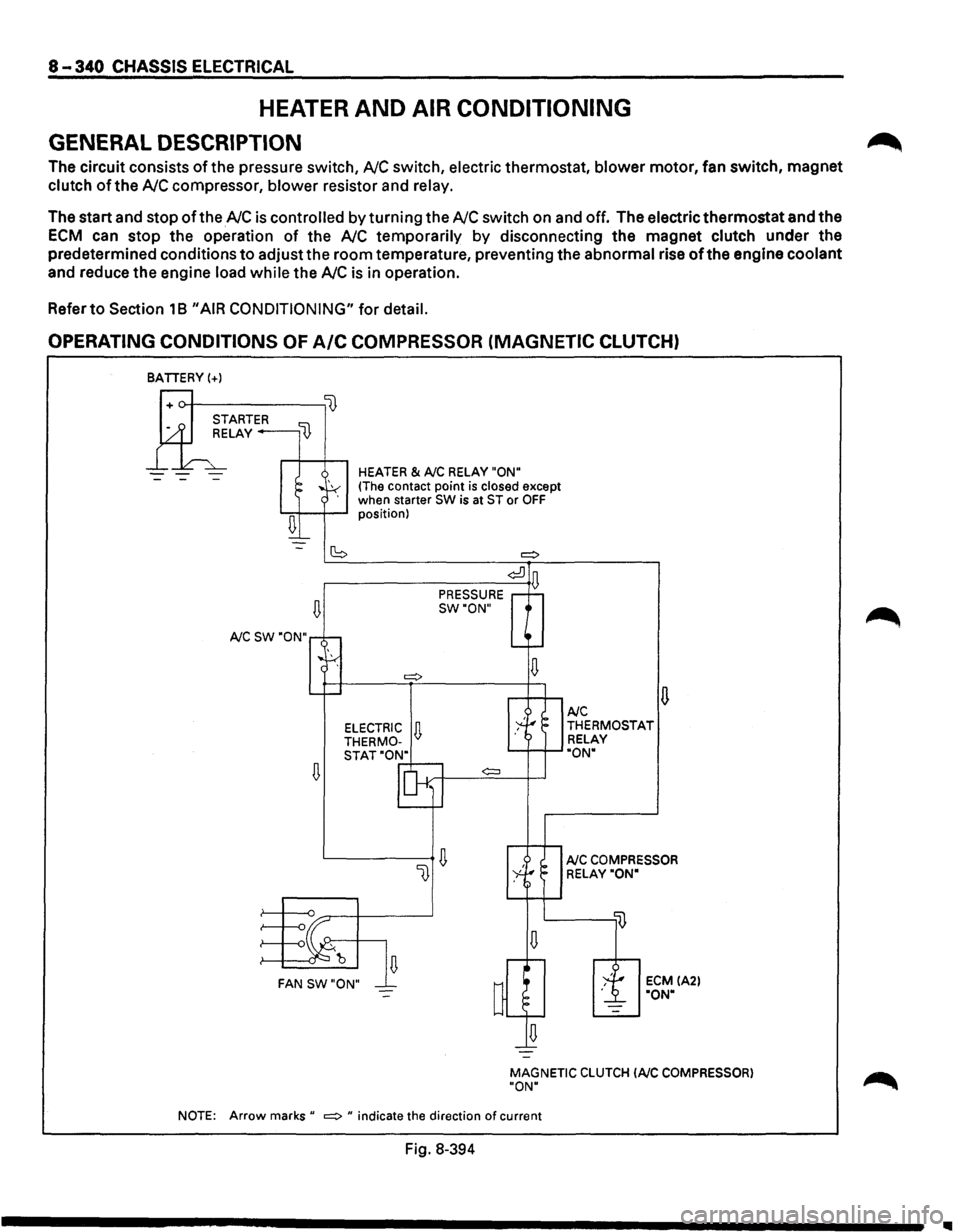
HEATER AND AIR CONDITIONING
GENERAL DESCRIPTION
The circuit consists of the pressure switch, NC switch, electric thermostat, blower motor, fan switch, magnet
clutch of the NC compressor, blower resistor and relay.
The start and stop of the NC is controlled by turning the NC switch on and off. The electric thermostat and the
ECM can stop the operation of the NC temporarily by disconnecting the magnet clutch under the
predetermined conditions
to adjust the room temperature, preventing the abnormal rise of the engine coolant
and reduce the engine load while the NC is in operation.
Refer
to Section 18 "AIR CONDITIONING" for detail.
OPERATING CONDITIONS OF A/C COMPRESSOR (MAGNETIC CLUTCH)
BATIERY(+)
--
~
A/C SW "ON"
~
HEATER & A/C RELAY "ON"
(The contact point is closed except
when starter SW is at ST or OFF position)
(S =:>
¢:!]
PRESSURE D
SW"ON"
¢:::l
~ FAN SW"ON"
u A/C THERMOSTAT
RELAY
"ON"
A/C COMPRESSOR
RELAY"ON"
ECM IA2l "ON"
MAGNETIC
CLUTCH lAIC COMPRESSOR)
"ON"
NOTE:
Arrow marks" =:> " indicate the direction of current
Fig. 8-394
~
1111
Page 1533 of 1928
CHASSIS ELECTRICAL 8-343
CONNECTOR LIST
'--"" ~ IB-191 [E) [E) [E) I B-361 [E] [TI]
o[J a 6 6 m ~ BiB 4
Fig. 8-397
Page 1534 of 1928
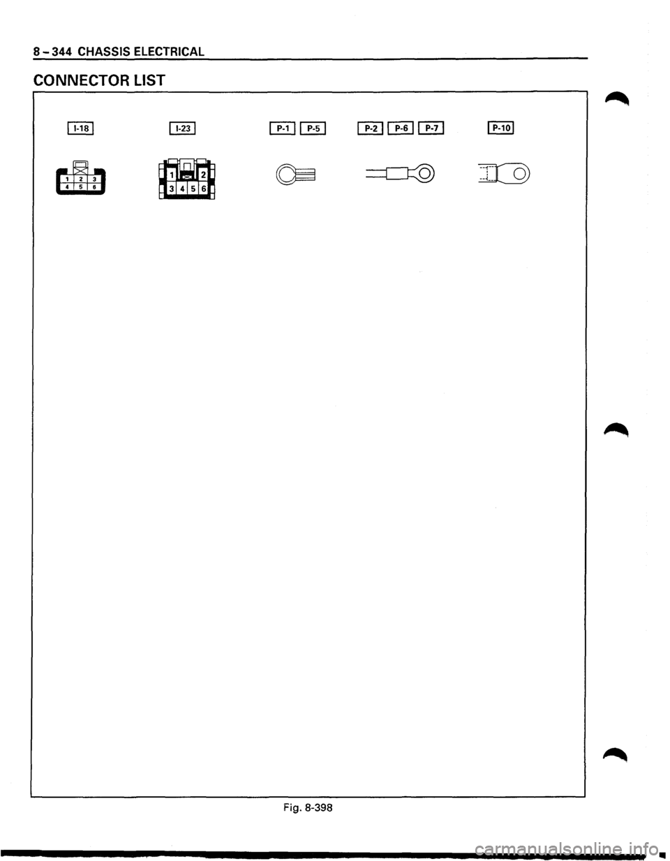
8-344 CHASSIS ELECTRICAL
CONNECTOR LIST
~
~
Fig. 8-398
..
Page 1535 of 1928
CHASSIS ELECTRICAL 8 _ 3
45
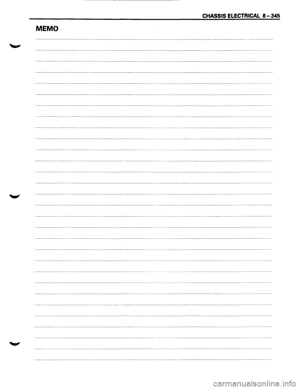
MEMO
Page 1536 of 1928
8-346 CHASSIS ELECTRICAL
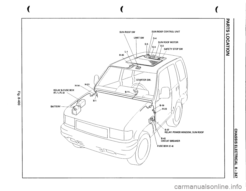
SUN ROOF
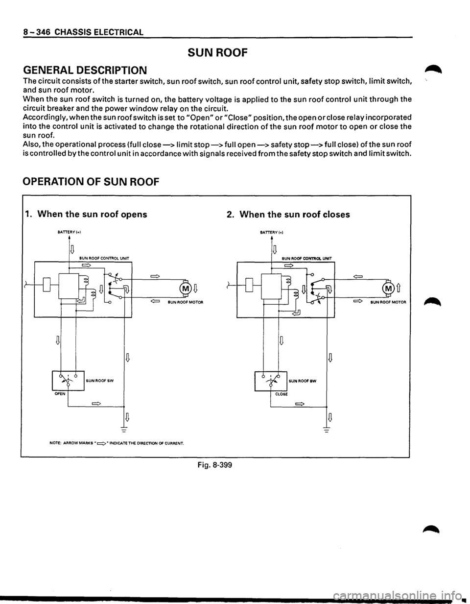
GENERAL DESCRIPTION
The circuit consists of the starter switch, sun roof switch, sun roof control unit, safety stop switch, limit switch,
and sun roof motor.
When the sun
roof switch is turned on, the battery voltage is applied to the sun roof control unit through the
circuit breaker and the power
window relay on the circuit.
Accordingly,
when the sun roof switch is set to "Open" or "Close" position, the open or close relay incorporated
into the control
unit is activated to change the rotational direction of the sun roof motor to open or close the
sun roof.
Also, the operational process (full close-> limit stop-> full open-> safety stop-> full close) ofthe sun roof
is
controlled by the control unit in accordance with signals received from the safety stop switch and limit switch.
OPERATION OF SUN ROOF
1. When the sun roof opens 2. When the sun roof closes
BATTERY(+!
BATTERY(+)
D D SUN ROOF CONTROL UNIT SUN ROO!' CONTIIOI. UNIT
D D
D
D
SUNROOF SW SUNROOFSW
D D
NOTE: ARROW MARKS • =:> • INDICATE THE DIRECTlON 01' CURRENT.
Fig. 8-399
Ill
Page 1537 of 1928
"'TI ce· (X) I "" 0 0
(
RELAY
& FUSE
BOX
IFL-1,
FL-2)
H-14
BATTERY
' -
,¢_
( SUN
ROOFSW
LIMITSW
SUN
ROOF
CONTROL
UNIT
SAFETY
STOP
SW
I " B-37 RELAY:
POWER
WINDOW,
SUN
ROOF
B-42 CIRCUIT
BREAKER
(
~ ::a -1 en r-0 (") ~ 0 2
0 :I: )> CJ) CJ) c;; m rm ~ ::D ~ r-eo I w .,. -..I
Page 1538 of 1928
8-348 CHASSIS ELECTRICAL
CIRCUIT DIAGRAM
+
E!JI'·1oiE2] BODY ENG. FRAME
811/R
.. ... 0
..
s
BODY·LHII~
C/8·2 30A POWER WINDOW, 8t SUN ROOF, P/SEAT 1
O.SB
SUNROOF CONTROL UNIT
0.58
• H
BODY·RHII B-1~--------------------------------------~2~8~----------------------------~
Fig. 8-401
Page 1539 of 1928
CHASSIS ELECTRICAL 8-349
CONNECTOR LIST
~ I B-111 I B-191 I s-421
r I
~ e
~II I i I I~ i !
11
1 ~ I I] alJ
{ 111 1211 8 -u--=--u
I B-371 I H-141 I H-211
I I
I I
6±8
~ i 6
~
4
2
I H-231 I H-451 [ill
I I I I I I
_r=1_
• Ia •
~
~m;rrrm!rn~ r@Jrm 615 m~ 6
~~ [EJ[EJ[EJ I P-10 I mJ [E]
r l I I
~ :::::c=J::Q) ICQ) -
m
I
~ ~
[E] [E]
!IJ
EWE 6
Fig. 8·402
Page 1540 of 1928
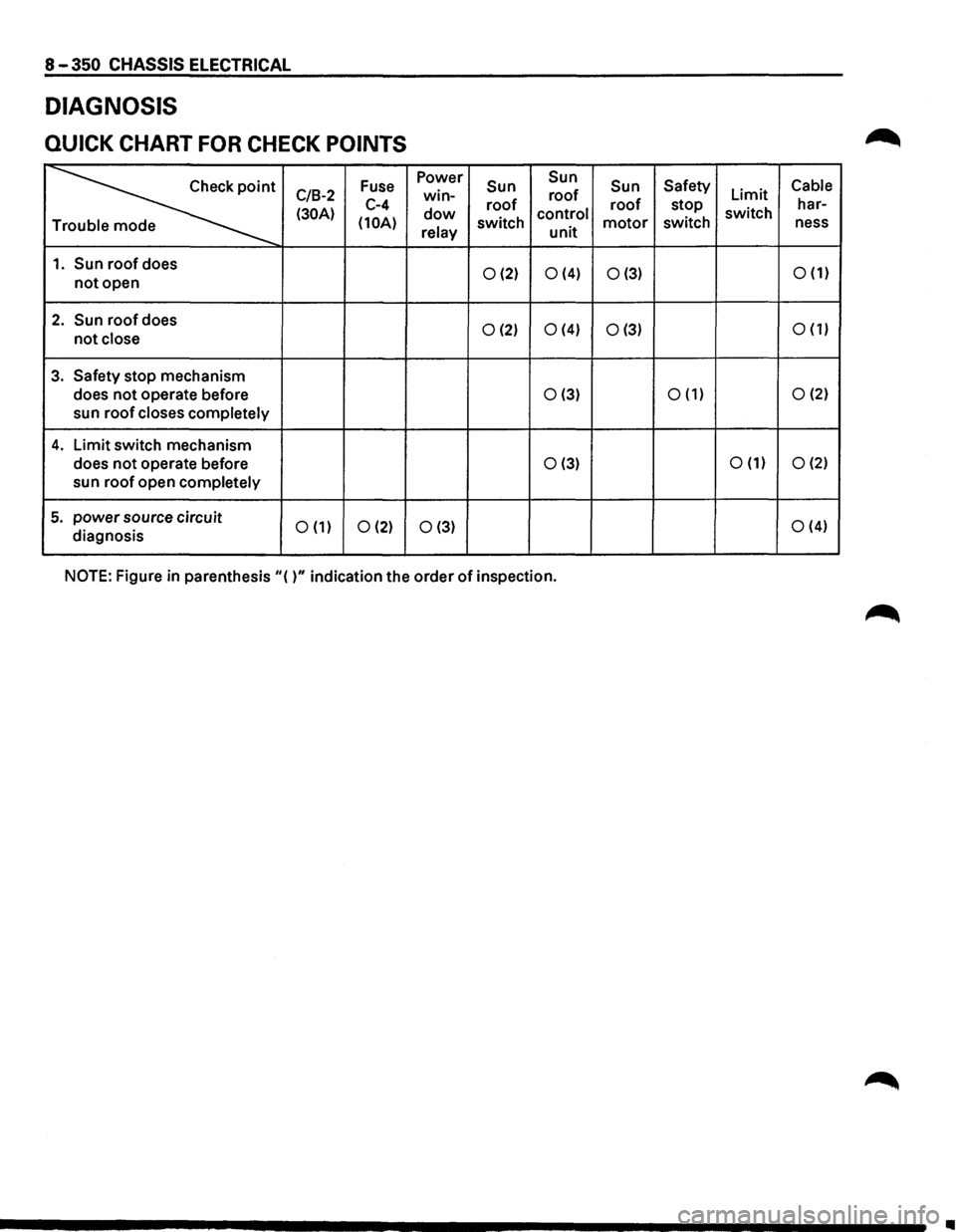
8 -350 CHASSIS ELECTRICAL
DIAGNOSIS
QUICK CHART FOR CHECK POINTS
~
Fuse Power Sun Sun
Sun Safety Cable
C/B-2 win-roof Limit
(30A) C-4 dow roof control roof stop switch har-
(10A) relay switch unit motor switch
ness T
1. Sun roof does 0 (2) 0 (4) 0 (3) 0 (1) not open
2. Sun roof does 0 (2) 0 (4) 0 (3) 0 (1) not close
3. Safety stop
mechanism
does
not operate before 0(3) 0 (1) 0 (2)
sun roof closes completely
4. Limit switch mechanism
does
not operate before 0 (3) 0 (1) 0 (2)
sun roof open completely
5. power source circuit 0 (1) 0 (2) 0 (3) 0 (4)
diagnosis
NOTE: Figure in parenthesis
"( )" indication the order of inspection.
Ill
![ISUZU TROOPER 1995 Workshop Manual CHASSIS ELECTRICAL 8-343
CONNECTOR LIST
--"" ~ IB-191 [E) [E) [E) I B-361 [E] [TI]
o[J a 6 6 m ~ BiB 4
Fig. 8-397](/img/61/57183/w960_57183-1532.png "ISUZU TROOPER 1995 Workshop Manual CHASSIS ELECTRICAL 8-343
CONNECTOR LIST
--\"\" ~ IB-191 [E) [E) [E) I B-361 [E] [TI]
o[J a 6 6 m ~ BiB 4
Fig. 8-397")
![ISUZU TROOPER 1995 Workshop Manual 8-348 CHASSIS ELECTRICAL
CIRCUIT DIAGRAM
+
E!JI·1oiE2] BODY ENG. FRAME
811/R
.. ... 0
..
s
BODY·LHII~
C/8·2 30A POWER WINDOW, 8t SUN ROOF, P/SEAT 1
O.SB
SUNROOF CONTROL UNIT
0.58
•](/img/61/57183/w960_57183-1537.png "ISUZU TROOPER 1995 Workshop Manual 8-348 CHASSIS ELECTRICAL
CIRCUIT DIAGRAM
+
E!JI·1oiE2] BODY ENG. FRAME
811/R
.. ... 0
..
s
BODY·LHII~
C/8·2 30A POWER WINDOW, 8t SUN ROOF, P/SEAT 1
O.SB
SUNROOF CONTROL UNIT
0.58
•")
![ISUZU TROOPER 1995 Workshop Manual CHASSIS ELECTRICAL 8-349
CONNECTOR LIST
~ I B-111 I B-191 I s-421
r I
~ e
~II I i I I~ i !
11
1 ~ I I] alJ
{ 111 1211 8 -u--=--u
I B-371 I H-141 I H-211
I I
I I
6±8
~ i 6
~
4
2
I H-23](/img/61/57183/w960_57183-1538.png "ISUZU TROOPER 1995 Workshop Manual CHASSIS ELECTRICAL 8-349
CONNECTOR LIST
~ I B-111 I B-191 I s-421
r I
~ e
~II I i I I~ i !
11
1 ~ I I] alJ
{ 111 1211 8 -u--=--u
I B-371 I H-141 I H-211
I I
I I
6±8
~ i 6
~
4
2
I H-23")