ISUZU TROOPER 1995 Workshop Manual
Manufacturer: ISUZU, Model Year: 1995, Model line: TROOPER, Model: ISUZU TROOPER 1995Pages: 1928
Page 1481 of 1928
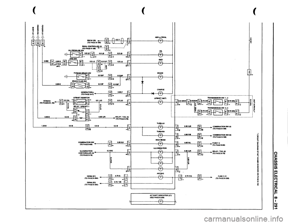
(
I
.. ~ !i:
----
~
........
II
0.858
0.858
0.38
0.85
G/R
1.258
0.58
0.58
0.38
CO-NATIONSW ITOPAGE~
~------_,
cg;c:=~31
0.3 RIG
I
ITO PAGE
8-7S}
:: I~
(
ASS
or RWAL
, • II
OIL ® .awl) ~ -CHARGE
IVT SHIFT
INDICATOR
()(71
{SEE PAGE
11-3351 r:::::-. ~
(
'o .. ~ I J
~~~~
~ ~ ~ '
---------------------------------------------------------
1----
COMBINAliON
8W 1'1
ITO PAGE
11-1011}
1----
CO-NATION
SW(S}
ITO PAGE
11-1011}
~~~~!tEll-SOl ~RELAY;TAILC'I
ITO PAGE
11-78} FUSEC-21 (TO PAGE
8-338}
. n ;;; ~ 0 ~ ;: 3: !il
0
~
::::t
~
)>
)>
(/)
II a;
(/)
..
c;;
~
m
0
r
z
m
... )>
0
~ !
-t ::D
~
c=; )> r co I N CD .....
Page 1482 of 1928
8-292 CHASSIS ELECTRICAL
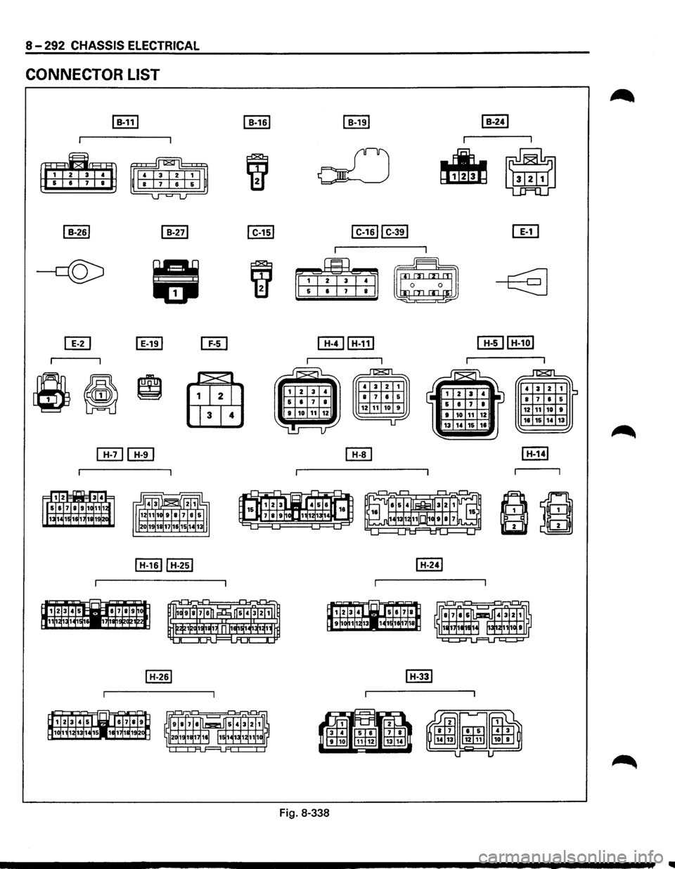
CONNECTOR LIST
~
4 a z 1 IS • 7 • 5 12 ,
10 •
18 16 14 13
Fig. 8-338
Page 1483 of 1928
CHASSIS ELECTRICAL 8 -293
I H-411 (W/ABSI I H-41 l!wtRWALI
~ J"T&Tl
' 3 2 1 ~~ 8 7 • 5 ' 3 2 1
8 7 • 5 12 11 10 9 12 11 10 9
16 15 14 13 1J
ITIHTIJ
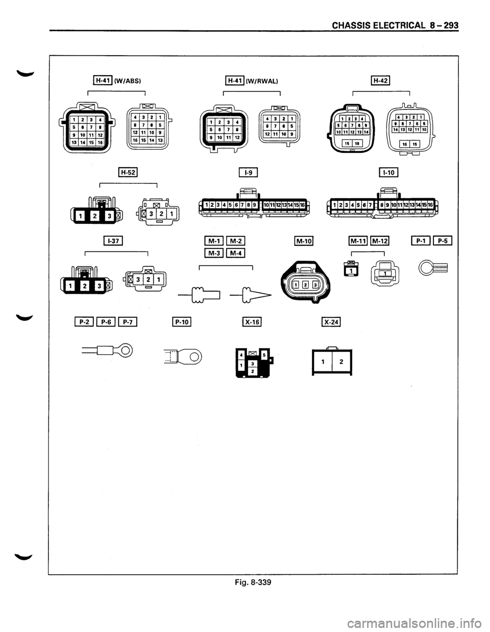
Fig. 8-339
Page 1484 of 1928
8-294 CHASSIS ELECTRICAL
DIAGNOSIS
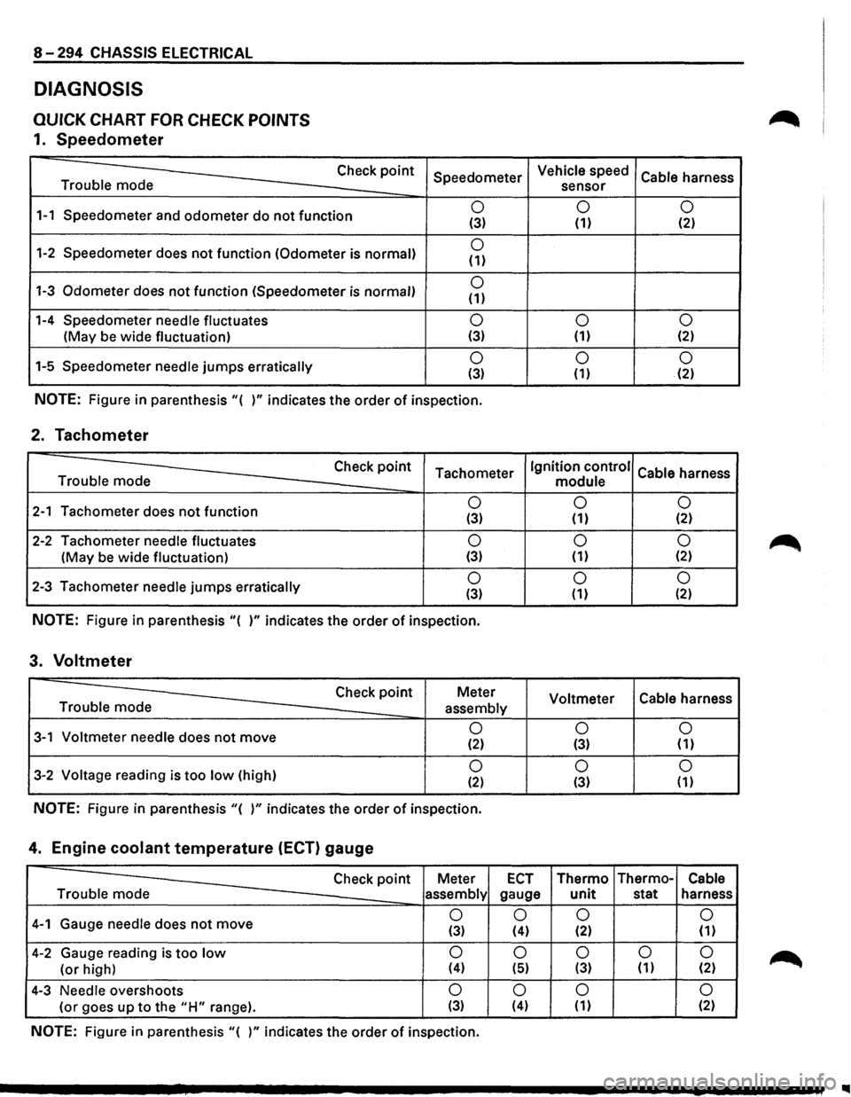
QUICK CHART FOR CHECK POINTS
1. Speedometer
Trouble mode Check
point
1-1 Speedometer
and odometer do not function
1-2 Speedometer does not function (Odometer is normal)
1-3 Odometer does not function (Speedometer is normal)
1-4 Speedometer needle fluctuates
(May be wide fluctuation)
1-5 Speedometer
needle jumps erratically Speedometer
0 (3)
0 (1)
0 (1)
0 (3)
0 (3)
NOTE: Figure
in parenthesis "( )" indicates the order of inspection.
2. Tachometer
Check point Tachometer Trouble mode
2-1 Tachometer does not function 0 (3)
2-2 Tachometer needle fluctuates 0
(May be wide fluctuation) (3)
2-3 Tachometer needle jumps erratically 0 (3)
NOTE: Figure in parenthesis "( )" indicates the order of inspection.
3. Voltmeter
Check point Meter
Trouble mode
assembly
3-1 Voltmeter needle does not move 0 (2)
3-2 Voltage reading is too low (high) 0 (2)
NOTE: Figure in parenthesis "( )" indicates the order of inspection.
4. Engine coolant temperature (ECT) gauge
Vehicle speed
Cable harness
sensor
0 0 (1) (2)
0
0 (1) (2)
0 0 (1) (2)
Ignition control
Cable harness
module
0 0
(1) (2)
0 0 (1) {2)
0 0 (1) (2)
Voltmeter Cable
harness
0 0 (3) (1)
0
0 (3) (1)
Check point Meter ECT Thermo Thermo-Cable
Trouble mode
assembly gauge unit stat harness
4-1 Gauge needle does not move 0
0 0
0
(3) (4) (2) (1)
4-2 Gauge reading is too low 0 0 0 0 0
(or high) (4) (5) (3) (1) (2)
4-3 Needle overshoots 0 0 0 0
(or goes up to the "H" range). (3) (4) (1) (2)
NOTE: Figure in parenthesis "( )" indicates the order of inspection.
..
Page 1485 of 1928
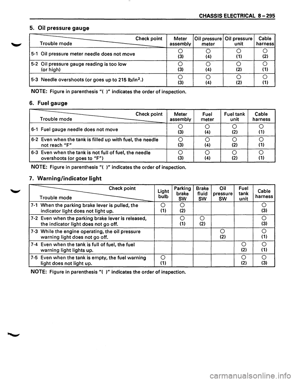
CHASSIS ELECTRICAL 8-295
5. Oil pressure gauge
Check point Meter Oil pressure Oil pressure Cable
Trouble mode
assembly meter unit harness
5-1 Oil pressure meter needle does not move 0
0 0
0 (3) (4) (1) (2)
5-2 Oil pressure
gauge reading is too low 0
0 0
0
(or
high) (3) (4) (2) (1)
5-3 Needle overshoots
(or goes up to 2151b/in2.) 0
0 0 0 (3) (4) (2)
(1)
NOTE: Figure
in parenthesis "( )" indicates the order of inspection.
6. Fuel gauge
Check point Meter Fuel Fuel tank Cable
Trouble mode assembly
meter unit harness
6-1 Fuel gauge needle does not move 0
0 0 0 (3) (4) (2) (1)
6-2 Even when the tank is filled up with fuel, the needle 0
0 0
0
not reach "F" (3) (4) (2)
(1)
6-3
Even when the tank is not full of fuel, the needle 0
0 0
0
overshoots (or goes to "F") (3) (4) (2) (1)
NOTE: Figure
in parenthesis "( )" indicates the order of inspection.
7. Warning/indicator light
~
Light Parking
Brake Oil Fuel Cable brake fluid pressure tank bulb sw sw sw unit harness
e
7-1 When the parking brake lever is pulled, the 0 0 0
indicator light does not light up. (1) (2) (3)
7-2 Even
when the parking brake lever is released, 0 0 0
the indicator light does not go off. (1) (2) (3)
7-3 While the engine operating,
the oil pressure 0 0
warning light does not go
off. (2)
(1)
7-4 Even
when the tank is full of fuel, the fuel 0 0
warning light lights
up. (2) (1)
7-5 Even
when the tank is empty, the fuel warning 0 0
0
light does not light up. (1) (2)
(3)
NOTE: Figure in parenthesis "( )" indicates the order of inspection.
Page 1486 of 1928
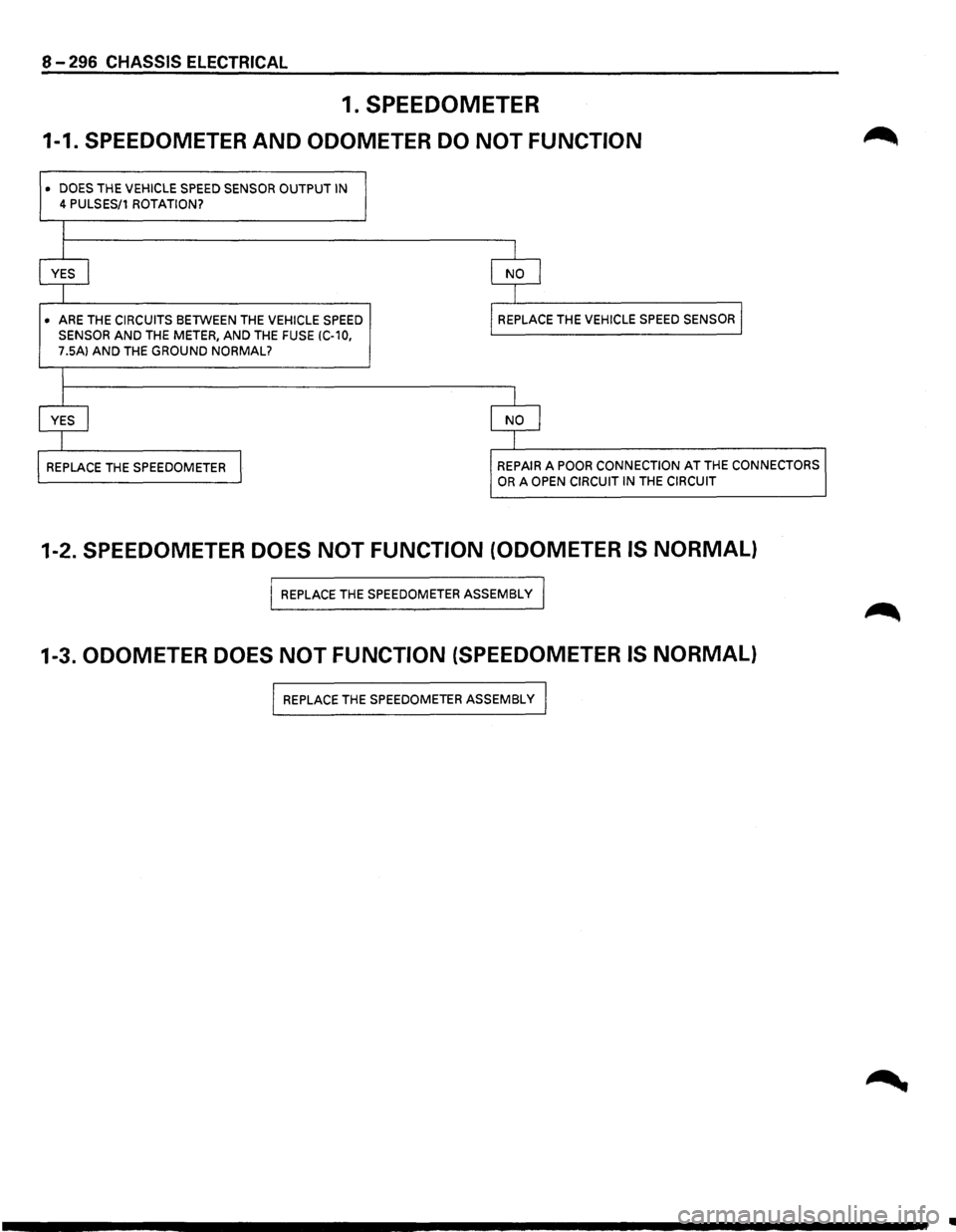
8-296 CHASSIS ELECTRICAL
1. SPEEDOMETER
1-1. SPEEDOMETER AND ODOMETER DO NOT FUNCTION
• DOES THE VEHICLE SPEED SENSOR OUTPUT IN
4 PULSES/1 ROTATION?
I
I I
YES I NO I
I
I
• ARE
THE CIRCUITS BETWEEN THE VEHICLE SPEED REPLACE
THE VEHICLE SPEED SENSOR I
SENSOR AND THE METER, AND THE FUSE (C-10,
7.5A) AND THE GROUND NORMAL?
I
j I
YES I NO I
I I
REPLACE
THE SPEEDOMETER I REPAIR A POOR CONNECTION AT THE CONNECTORS
OR A OPEN CIRCUIT IN THE CIRCUIT
1-2. SPEEDOMETER DOES NOT FUNCTION (ODOMETER IS NORMAL)
I REPLACE THE SPEEDOMETER ASSEMBLY I
1-3. ODOMETER DOES NOT FUNCTION (SPEEDOMETER IS NORMAL)
I REPLACE THE SPEEDOMETER ASSEMBLy I
..
Page 1487 of 1928
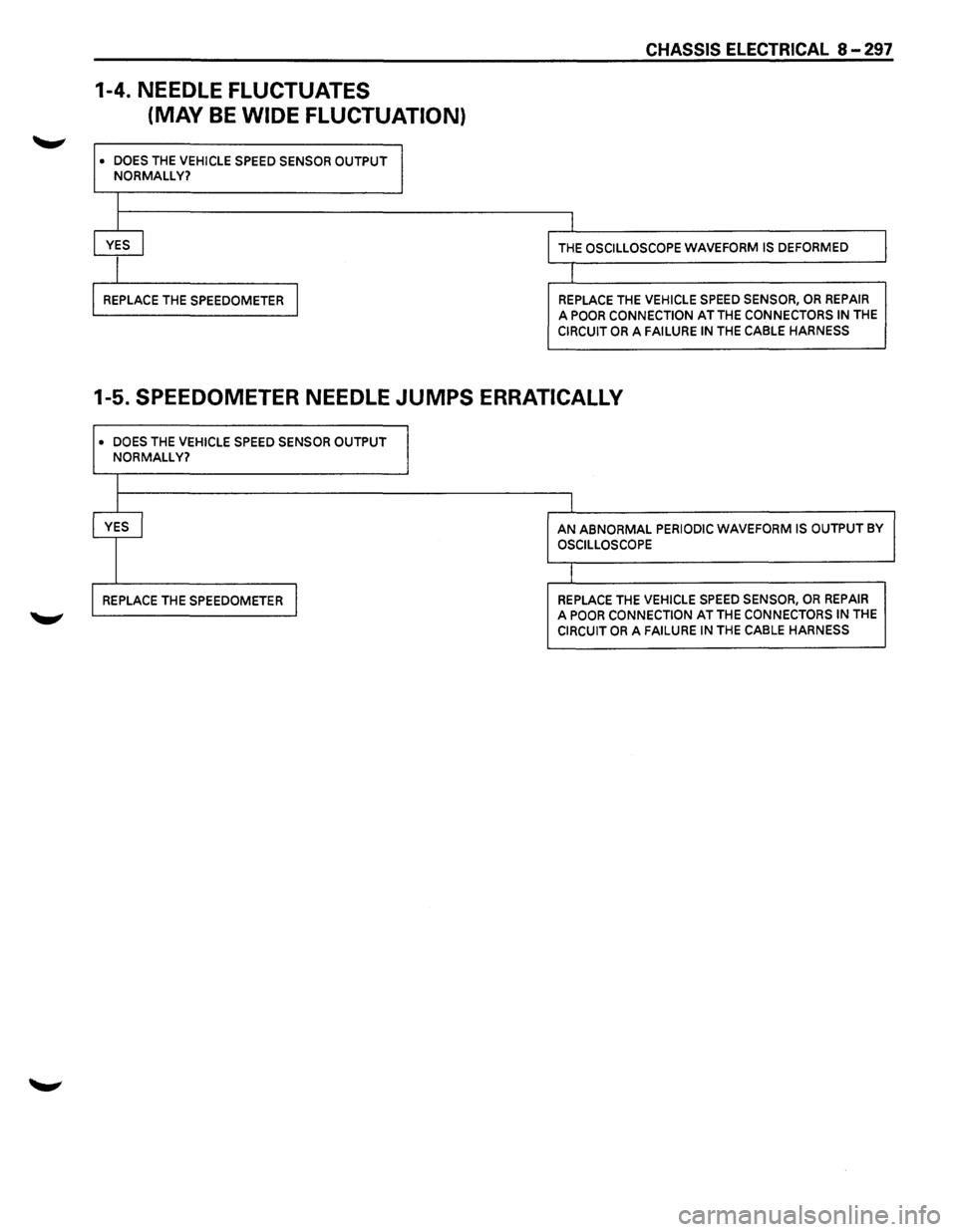
CHASSIS ELECTRICAL 8-297
1-4. NEEDLE FLUCTUATES
(MAY
BE WIDE FLUCTUATION)
• DOES THE VEHICLE SPEED SENSOR OUTPUT
NORMALLY?
I
I
l
YES ~ THE OSCILLOSCOPE WAVEFORM IS DEFORMED
I r
REPLACE THE SPEEDOMETER I REPLACE THE VEHICLE SPEED SENSOR, OR REPAIR
A POOR CONNECTION AT THE CONNECTORS IN THE
CIRCUIT OR A FAILURE IN THE CABLE HARNESS
1-5. SPEEDOMETER NEEDLE JUMPS ERRATICALLY
• DOES THE VEHICLE SPEED SENSOR OUTPUT
NORMALLY?
I
YES I AN ABNORMAL PERIODIC WAVEFORM IS OUTPUT BY
OSCILLOSCOPE
I
REPLACE THE SPEEDOMETER I REPLACE THE VEHICLE SPEED SENSOR, OR REPAIR A POOR CONNECTION AT THE CONNECTORS IN THE CIRCUIT OR A FAILURE IN THE CABLE HARNESS
Page 1488 of 1928
![ISUZU TROOPER 1995 Workshop Manual 8 -298 CHASSIS ELECTRICAL
Inspection of a waveform by oscilloscope
1. Connect a resistance of 1.3 to 5k ohm (1.4W or more) between the harness side connectors 14[ill
and 8 [ElQ] of the meter.](/img/61/57183/w960_57183-1487.png "ISUZU TROOPER 1995 Workshop Manual 8 -298 CHASSIS ELECTRICAL
Inspection of a waveform by oscilloscope
1. Connect a resistance of 1.3 to 5k ohm (1.4W or more) between the harness side connectors 14[ill
and 8 [ElQ] of the meter.")
8 -298 CHASSIS ELECTRICAL
Inspection of a waveform by oscilloscope
1. Connect a resistance of 1.3 to 5k ohm (1.4W or more) between the harness side connectors 14[ill
and 8 [ElQ] of the meter.
2. Install a speedometer tester.
2. Turn on the starter SW.
3. Check the waveform at the time when the vehicle speed is at 37mph.
I Normal waveform I
ov 4-
A
-
23.6m sec. i
pproximate battery voltage -2V
Max. 2V
Fig. 8-340
2. TACHOMETER
2-1 TACHOMETER DOES NOT FUNCTION
I· IS THE PULSE INPUT NORMAL? l
I
I
I YES I
I
I REPLACE THE TACHOMETER I
I
NO I
I
REPLACE THE IGNITION CONTROL MODULE, OR REPAIR A POOR CONNECTION OF THE CONNECTORS
IN THE CIRCUIT OR A FAILURE IN THE CABLE HARNESS
Page 1489 of 1928
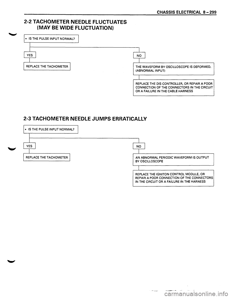
2-2 TACHOMETER NEEDLE FLUCTUATES
(MAY
BE WIDE FLUCTUATION)
I· IS THE PULSE INPUT NORMAL? I
I
I
f YES l
I
I REPLACE THE TACHOMETER I
CHASSIS ELECTRICAL 8-299
I
NO j
l
THE WAVEFORM BY OSCILLOSCOPE IS DEFORMED. (ABNORMAL INPUT)
I
REPLACE THE DIS CONTROLLER, OR REPAIR A POOR
CONNECTION OF THE CONNECTORS IN THE CIRCUIT OR A FAILURE IN THE CABLE HARNESS
2-3 TACHOMETER NEEDLE JUMPS ERRATICALLY
I· IS THE PULSE INPUT NORMAL? I
I
I
I
I YES I NO j
I I
I REPLACE THE TACHOMETER I AN ABNORMAL PERIODIC WAVEFORM IS OUTPUT BY OSCILLOSCOPE
I
REPLACE THE IGNITON CONTROL MODULE, OR REPAIR A POOR CONNECTION OF THE CONNECTORS IN THE CIRCUIT OR A FAILURE IN THE HARNESS
Page 1490 of 1928
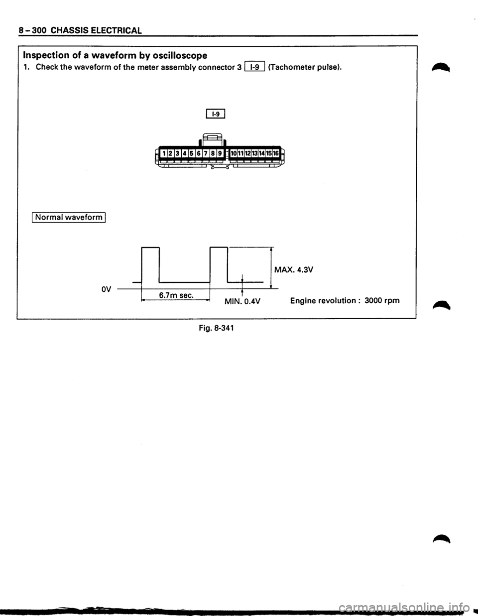
8-300 CHASSIS ELECTRICAL
Inspection of a waveform by oscilloscope
1. Check the waveform of the meter assembly connector 3 ~ (Tachometer pulse).
I Normal waveform I
....---r---
MAX. 4.3V
~ -
MIN. 0.4V Engine revolution: 3000 rpm
I
6.7m sec.
'
ov
Fig. 8-341
..