ISUZU TROOPER 1995 Workshop Manual
Manufacturer: ISUZU, Model Year: 1995, Model line: TROOPER, Model: ISUZU TROOPER 1995Pages: 1928
Page 1521 of 1928
![ISUZU TROOPER 1995 Workshop Manual OIL PRESSURE UNIT
(1!] INSPECTION
Measure the resistance value ofthe oil pressure unit
with the circuit tester. (Fig. 8-377)
Replace the
unit when the result of inspection is found
abnorm](/img/61/57183/w960_57183-1520.png "ISUZU TROOPER 1995 Workshop Manual OIL PRESSURE UNIT
(1!] INSPECTION
Measure the resistance value ofthe oil pressure unit
with the circuit tester. (Fig. 8-377)
Replace the
unit when the result of inspection is found
abnorm")
OIL PRESSURE UNIT
(1!] INSPECTION
Measure the resistance value ofthe oil pressure unit
with the circuit tester. (Fig. 8-377)
Replace the
unit when the result of inspection is found
abnormal.
Pressure
(kPa)
Resistance value (Q)
Fig. 8-377
OIL PRESSURE SWITCH
(1!] INSPECTION
98 981
81 30
I~~ Check the continuity between the switch termi
nal and the body ground with the engine at idle.
(Fig. 8-378)
Replace the switch when the result
of inspection
is
found abnormal.
Fig. 8-378
CHASSIS ELECTRICAL 8-331
(1!] CIRCUIT INSPECTION (FIG. 8-379)
Fig. 8-379
1. Start the engine.
2. When disconnecting the oil pressure switch con
nector then connecting the harness side connec
tor to the ground, check to see if the oil pressure
warning light lights up.
When the
light will not light up, check the circuit
between the meter and the oil pressure switch,
and repair
an open circuit if necessary.
FUEL TANK UNIT
The tank unit varies the internal resistance according
to the float position (fluid level) to operate the fuel
meter needle.
It is also designed
to warn the driver of low fuel level
by illuminating the fuel warning light. (Fig. 8-380)
Fig. 8-380
Page 1522 of 1928
![ISUZU TROOPER 1995 Workshop Manual 8-332 CHASSIS ELECTRICAL
i1!]1NSPECTION
~1.
£ ·= 01 ~ N ~ !:!i E
E
E E
0 M (I) ..., ... ...
Check the resistance between the connector
terminals 1 [E[I and 2 [E[J while shifting
the fl](/img/61/57183/w960_57183-1521.png "ISUZU TROOPER 1995 Workshop Manual 8-332 CHASSIS ELECTRICAL
i1!]1NSPECTION
~1.
£ ·= 01 ~ N ~ !:!i E
E
E E
0 M (I) ..., ... ...
Check the resistance between the connector
terminals 1 [E[I and 2 [E[J while shifting
the fl")
8-332 CHASSIS ELECTRICAL
i1!]1NSPECTION
~1.
£ ·= 0'1 ~ N ~ !:!i E
E
E E
0 M (I) ..., ... ...
Check the resistance between the connector
terminals 1 [E[I and 2 [E[J while shifting
the float from "E" to "F" point.
When
the resistance shows no change, or
deflects largely from the specified value, re
place the fuel tank unit. (Fig. 8-381)
F
E .:: E~ ...... ...,::;
X
E
NOTE:
When the resistance value at E point is checked,
connect
the terminal 2 ~ to the battery (+) ter
minal and 1 [E[] to the battery (-) terminal under
the condition that ambient temperature is between
20°C and 30°C (68°F and 86°F).
.. ,
I I I
·-·
Float position Resistance value (Q)
F point 17 ± 0.8
1/2 point 45± 1.5
E
point 120±5
Fig. 8-381
2. Check the resistance value between the fuel tank 1++1 REMOVAL (FIG. 8-383) unit connector terminals 1 ~and 4 [£:[].
(Fig. 8-382) Preparation: Disconnect the battery ground cable.
Replace the fuel tank unit when the result of
inspection is found abnormal.
Float
position Terminal No. Resistance
value (Q)
X point Undercover (Light up point 1-4 35.9-18 of low fuel Fig.
8-383 warning light)
Fig. 8-382
Ill
Page 1523 of 1928
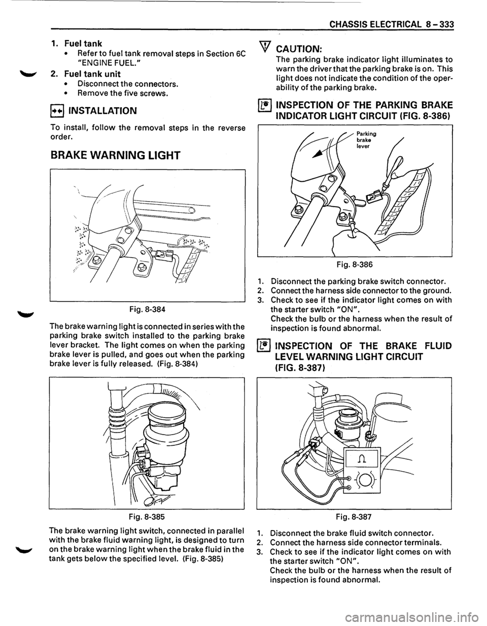
1. Fuel tank
• Refer to fuel tank removal steps in Section 6C
"ENGINE FUEL."
2. Fuel tank unit
• Disconnect the connectors.
• Remove the five screws.
B INSTALLATION
To install, follow the removal steps in the reverse
order.
BRAKE WARNING LIGHT
Fig. 8-384
The brake
warning light is connected in series with the
parking brake switch
installed to the parking brake
lever bracket. The
light comes on when the parking
brake lever is
pulled, and goes out when the parking
brake lever is
fully released. (Fig. 8-384)
Fig. 8-385
The brake warning
light switch, connected in parallel
with the brake fluid warning light, is designed to turn
on the brake warning light when the brake fluid in the
tank gets
below the specified level. (Fig. 8-385)
CHASSIS ELECTRICAL 8-333
"f CAUTION:
The parking brake indicator light illuminates to
warn the driver that the parking brake is on. This
light does not indicate the condition of the oper
ability of the parking brake.
~ INSPECTION OF THE PARKING BRAKE
INDICATOR LIGHT CIRCUIT (FIG. 8-386)
Fig. 8-386
1. Disconnect the parking brake switch connector.
2. Connect the harness side connector to the ground.
3. Check to see if the indicator light comes on with
the starter switch "ON".
Check the bulb or the harness when the result of
inspection is found abnormal.
~ INSPECTION OF THE BRAKE FLUID
LEVEL WARNING LIGHT CIRCUIT
(FIG.
8-387)
Fig. 8-387
1. Disconnect the brake fluid switch connector.
2. Connect the harness side connector terminals.
3. Check to see if the indicator light comes on with
the starter switch "ON".
Check the bulb or the harness when the result of
inspection is found abnormal.
Page 1524 of 1928
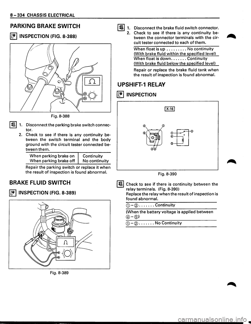
8-334 CHASSIS ELECTRICAL
PARKING BRAKE SWITCH
~ INSPECTION (FIG. 8-388)
Fig. 8-388
I ti!!.l 1. Disconnect the parking brake switch connec
tor.
2. Check to see if there is any continuity be
tween the switch terminal and the
body
ground with the circuit tester connected be
tween them.
When parking brake on
Continuity
When parking brake off No continuity
Repair the parking switch
or replace it when
the result
of inspection is found abnormal.
BRAKE FLUID SWITCH
~ INSPECTION (FIG. 8-389)
Fig. 8-389
1311. Disconnectthebrakefluidswitchconnector.
2. Check to see if there is any continuity be-...-...
tween the connector terminals with the cir--..
cuit tester connected to each of them.
When float is up ......... No continuity
(With brake fluid within the specified level)
When float is
down ....... Continuity
(With brake fluid
below the specified level)
Repair
or replace the brake fluid tank when
the result
of inspection is found abnormal.
UPSHIFT-1 RELAY
~ INSPECTION
®ijf ®
-UJ
ill®
Fig. 8-390
131 Check to see if there is continuity between the
relay terminals. (Fig.
8-390)
Replace the relay when the result of inspection is
found abnormal.
G)-® ....... Continuity
(When the battery voltage is applied between
@-@)
G)-® ....... No Continuity
..
Page 1525 of 1928
CHASSIS ELECTRICAL 8-335
MEMO
Page 1526 of 1928
8-336 CHASSIS ELECTRICAL
A/T SHIFT INDICATOR
GENERAL DESCRIPTION
The circuit consists ofthe starter switch, lighting switch, mode switch, A/T shift indicator control unit and A/T
shift indicator (meter).
Ill
Page 1527 of 1928
 I w (0 .....
(
ANTI-THEFT
CONTROLLER
RELAY;
TAIL
RELAY
& FUSE
BOX
\
(FL-
1, FL-2,
F-12)
\"\"
BATIERY
H-41
H-12 H-14
(
STARTERSW
111
1 l
I
I
\V
H-8
B-19
FUSE
B")
'"T1 ce· 0) I w (0 .....
(
ANTI-THEFT
CONTROLLER
RELAY;
TAIL
RELAY
& FUSE
BOX
\
(FL-
1, FL-2,
F-12)
""'
BATIERY
H-41
H-12 H-14
(
STARTERSW
111
1 l
I
I
\V
H-8
B-19
FUSE
BOX
IC-3)
B-12 A/T
SHIFT
INDICOTOR
CONTROL
UNIT
(
~ :a ~ r-0 n ~ -0 2
~ ln (I) c;; m r-·~ ;I ~ 00 I ~ ....
Page 1528 of 1928
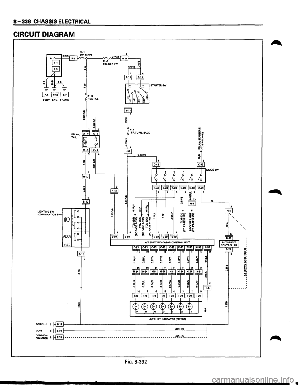
8-338 CHASSIS ELECTRICAL
CIRCUIT DIAGRAM
+ o---I..::B..::Bi::.:RCj
~
B
~~P-1ol~ BODY ENG. FRAME
LIGHTINGSW (COMBINATION SWI
SODV-LH II
DUCT II
"' .. 0
rJ ill 0
13
C-3 15A TURN, BACK
~ ~ ._ ~~ ~~ ~ "~ ~~ ~m ~~ 0 0 ~= :lab !Sill ~= ~= ~= .. ~ ~~ 1-CJ 1-CJ 1-.., ~ ~ f. g :ag 0 g
g t:.
/>IT SHIFT INDICATOR (METERI
IDOHCI ' ~~~ 11~--------------------------------------------------------J~~g ___________ J
Fig. 8-392
2L
12
' t: ~:
il o• ~: ... : "!• o, '
1111
Page 1529 of 1928
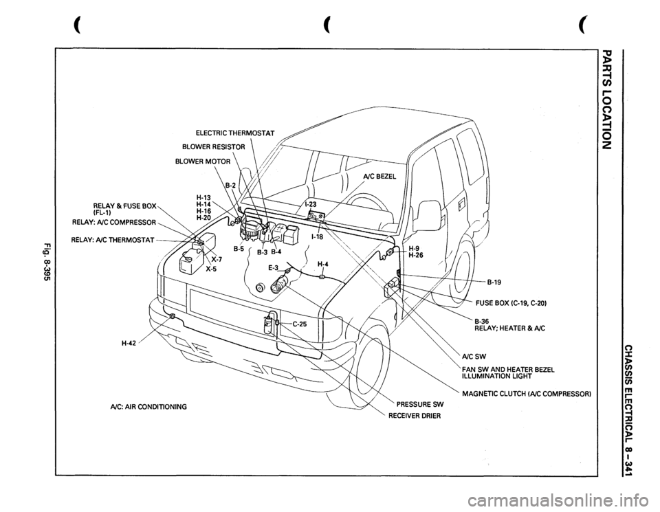
'"T1 cO' co w
RELAY
& FUSE
BOX
(FL-11
RELAY:
NC
COMPRESSOR
BLOWER
MOTOR
RELAY:
NCTHERMOSTAT
,,-;~
H-42'
NC:
AIR
CONDITIONING
(
PRESSURE
SW
RECEIVER
DRIER
B-19
FUSE
BOX
(C-19,
C-201
B-36 RELAY;
HEATER
& NC
NCSW FAN
SW
AND
HEATER
BEZEL
ILLUMINATION
LIGHT
(
MAGNETIC
CLUTCH
INC
COMPRESSOR)
;g ::0 ~ r-0 0 ~ 0 2
n :::J: )> en en Cii m rm ~ ::u n )> r-eo I w ~ ...a
Page 1530 of 1928
![ISUZU TROOPER 1995 Workshop Manual 8 -342 CHASSIS ELECTRICAL
CIRCUIT DIAGRAM
~ IOOV
M:LAV; 8TARTERI1) ITO PAOEI· .. I
E!]~ ENG. ftAME
. :l
. 5
IOOV-11< II
2L
I LOWER MOTOR
fiiELAY; HEATEfii6AIC
C·1t 21A BLOWER
A/C: AI](/img/61/57183/w960_57183-1529.png "ISUZU TROOPER 1995 Workshop Manual 8 -342 CHASSIS ELECTRICAL
CIRCUIT DIAGRAM
~ IOOV
M:LAV; 8TARTERI1) ITO PAOEI· .. I
E!]~ ENG. ftAME
. :l
. 5
IOOV-11< II
2L
I LOWER MOTOR
fiiELAY; HEATEfii6AIC
C·1t 21A BLOWER
A/C: AI")
8 -342 CHASSIS ELECTRICAL
CIRCUIT DIAGRAM
~ IOOV
M:LAV; 8TARTERI1) ITO PAOEI· .. I
E!]~ ENG. ft'AME
. :l
. 5
IOOV-11< II
2L
I LOWER MOTOR
'
fiiELAY; HEATEfii6AIC
C·1t 21A BLOWER
A/C: AIR CONDITIONING
O.IIR O.IIR
IOOV~ 11~----------------------------------------------------------__J
Fig. 8-396
22
H·11
..