ISUZU TROOPER 1995 Workshop Manual
Manufacturer: ISUZU, Model Year: 1995, Model line: TROOPER, Model: ISUZU TROOPER 1995Pages: 1928
Page 1541 of 1928
CHASSIS ELECTRICAL 8-351
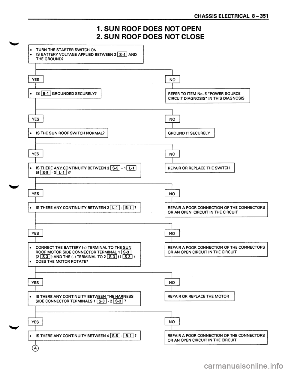
1. SUN ROOF DOES NOT OPEN
2. SUN ROOF DOES NOT CLOSE
• TURN THE STARTER SWITCH ON
• IS BATTERY VOLTAGE APPLIED BETWEEN 21 S-41 AND THE GROUND?
I
YES I NO J
I
• IS ~GROUNDED SECURELY? I REFER TO ITEM No.5 uPOWER SOURCE
CIRCUIT DIAGNOSISu IN THIS DIAGNOSIS
I
YES I NO I
I
• IS THE SUN ROOF SWITCH NORMAL? I GROUND IT SECURELY I
I
YES j NO I
I
• IS THERE ANY CONTINUITY BETWEEN 3 ~-1 ~ REPAIR OR REPLACE THE SWITCH I lSI s-si-3[BJl?
I
YES I NO I
I
• IS THERE ANY CONTINUITY BETWEEN 2 [BJ-~? REPAIR A POOR CONNECTION OF THE CONNECTORS OR AN OPEN CIRCUIT IN THE CIRCUIT
I
YES I NO I
I
• CONNECT THE BATTERY(+) TERMINAL TO THE SUN REPAIR A POOR CONNECTION OF THE CONNECTORS
ROOF MOTOR SIDE CONNECTOR TERMINAL
1 ~ OR AN OPEN CIRCUIT IN THE CIRCUIT
(2 ~I AND THE(-) TERMINAL TO 2 ~ (1 S-3 I
• DOES THE MOTOR ROTATE?
I
YES I NO I
I
• IS THERE ANY CONTINUITY BETWEEN THE HARNESS REPAIR OR REPLACE THE MOTOR I SIDE CONNECTOR TERMINALS 1 ~-21 S-31 ?
I
YES I NO I
I
• IS THERE ANY CONTINUITY BETWEEN 4 ~-~ ? REPAIR A POOR CONNECTION OF THE CONNECTORS
0
OR AN OPEN CIRCUIT IN THE CIRCUIT
Page 1542 of 1928
8-352 CHASSIS ELECTRICAL
~
I
I YES I
I
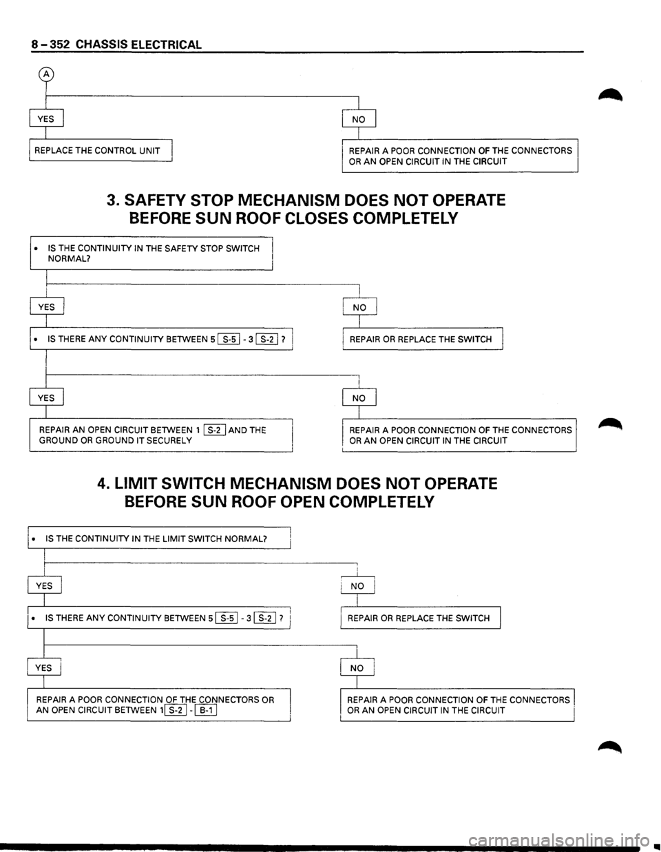
I REPLACE THE CONTROL UNIT I
I
NO I
I
REPAIR A POOR CONNECTION OF THE CONNECTORS
OR AN OPEN CIRCUIT IN THE CIRCUIT
3. SAFETY STOP MECHANISM DOES NOT OPERATE
BEFORE
SUN ROOF CLOSES COMPLETELY
• IS THE CONTINUITY IN THE SAFETY STOP SWITCH
NORMAL?
i
YES I
• IS THERE ANY CONTINUITY BETWEEN 5 ~ - 3 ~? I
YES I
REPAIR AN OPEN CIRCUIT BETWEEN 1 ~AND THE GROUND OR GROUND IT SECURELY
~~------------~
I REPAIR OR REPLACE THE SWITCH
I NO ,___.
!I REPAIR A POOR CONNECTION OF THE CONNECTORS OR AN OPEN CIRCUIT IN THE CIRCUIT
4. LIMIT SWITCH MECHANISM DOES NOT OPERATE
BEFORE
SUN ROOF OPEN COMPLETELY
• IS THE CONTINUITY IN THE LIMIT SWITCH NORMAL?
~ + ~ I
• IS THERE ANY CONTINUITY BETWEEN 5 ~-3 ~? i
REPAIR A POOR CONNECTION OF THE CONNECTORS OR AN OPEN CIRCUIT BETWEEN 11liJ-~
REPAIR OR REPLACE THE SWITCH
REPAIR
A POOR CONNECTION OF THE CONNECTORS OR AN OPEN CIRCUIT IN THE CIRCUIT I
..
Page 1543 of 1928
CHASSIS ELECTRICAL 8-353
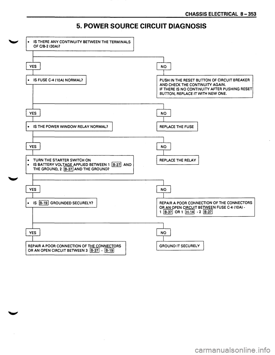
5. POWER SOURCE CIRCUIT DIAGNOSIS
• IS THERE ANY CONTINUITY BETWEEN THE TERMINALS
OF C/B-2 130Al?
I
YES I NO I
I
• IS FUSE C-4 (10Al NORMAL? I PUSH IN THE RESET BUTION OF CIRCUIT BREAKER
AND CHECK THE CONTINUITY AGAIN. IF THERE IS NO CONTINUITY AFTER PUSHING RESET BUTION, REPLACE IT WITH NEW ONE.
I
YES I NO I
I
• IS THE POWER WINDOW RELAY NORMAL? I REPLACE THE FUSE I
I
YES I NO I
I
• TURN THE STARTER SWITCH ON REPLACE THE RELAY I
• IS BATIERY VOLTAGE APPLIED BETWEEN 1 I B-371 AND THE GROUND, 2 IB-371 AND THE GROUND?
1
YES I NO I
I
• IS IB-191 GROUNDED SECURELY? I REPAIR A POOR CONNECTION OF THE CONNECTORS
OR AN OPEN CIRCUIT BETWEEN FUSE C-4 (10A)-
1 IB-371 OR 1 IH-141 -2 IB-371
I
YES I NO I
I
REPAIR A POOR CONNECTION OF THE CONNECTORS GROUND IT SECURELy I
OR AN OPEN CIRCUIT BETWEEN 3 IB-371 -IB-191
Page 1544 of 1928
8-354 CHASSIS ELECTRICAL
STARTER SWITCH
Refer to "Start and Charging" in this section.
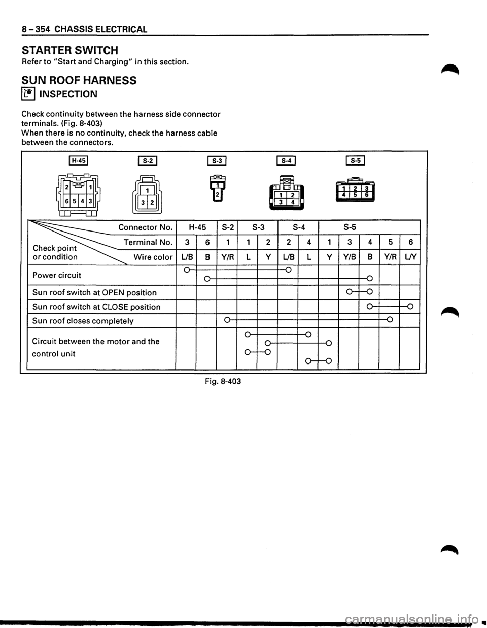
SUN ROOF HARNESS
~ INSPECTION
Check continuity between the harness side connector
terminals. (Fig. 8-403)
When there is no continuity, check the harness cable
between the connectors.
I H-451 em [IT]
II I
~
~ H-45 S-2 ~onnector No.
C Terminal No. 3 6 1 t
or Wire color LIB B Y/R
0 Power circuit 0
Sun roof switch
at OPEN position
Sun roof switch at CLOSE position
Sun roof closes completely
Circuit between the motor and the
control unit
Fig. 8-403
[EJ [ill
!I!
BmB 6
S-3
S-4 S-5
1 2 2 4 1 3 4 5 6
L y LIB L y Y/B B Y/R L/Y
{) ,... .....,
o--o
{)
,... .....,
0 {) ,...
,...
o-~
.....,
o--o
IIIII
Page 1545 of 1928
CHASSIS ELECTRICAL 8-355
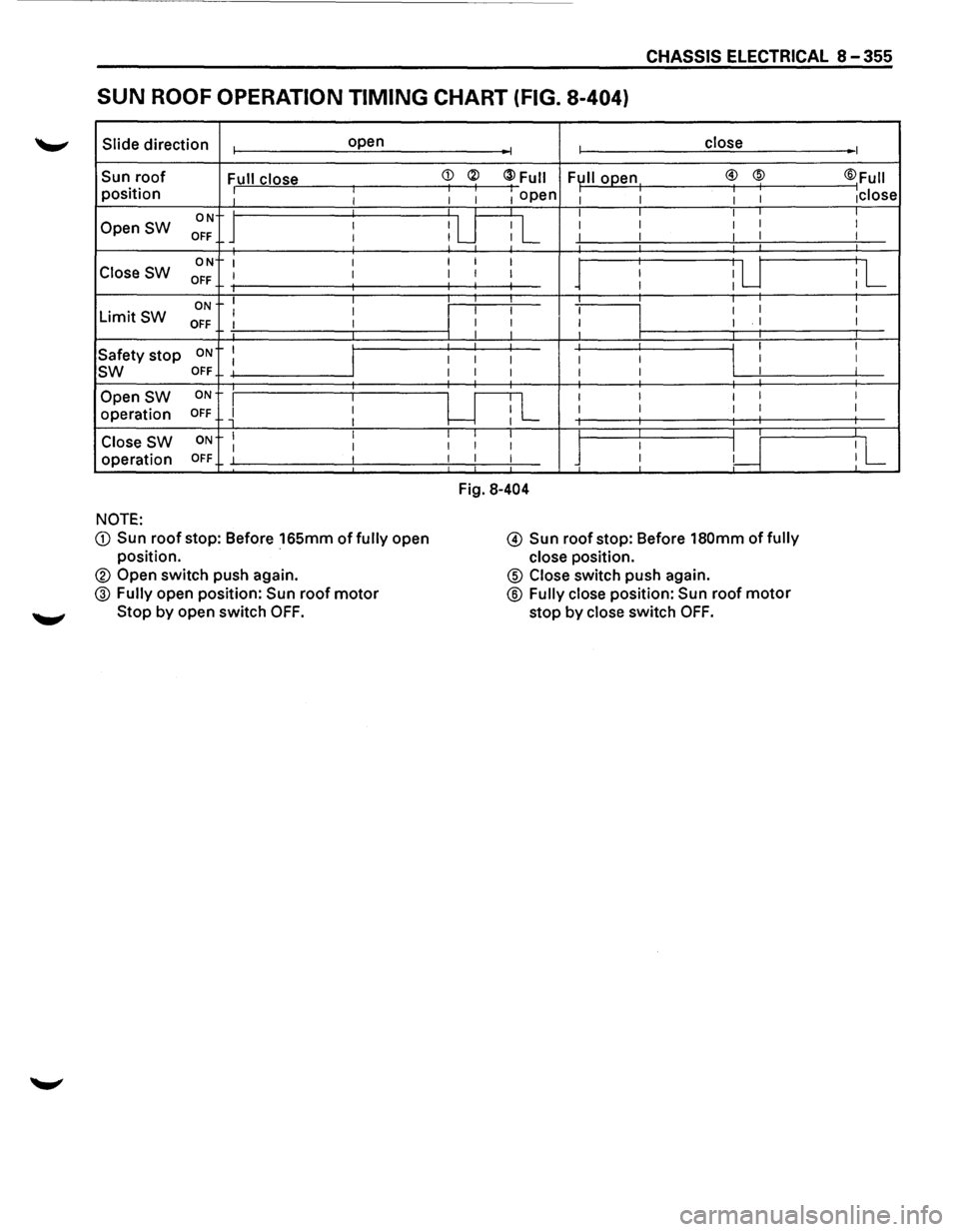
SUN ROOF OPERATION TIMING CHART (FIG. 8-404)
Slide direction open
Sun roof Full close position : I
ON Open SW I
OFF I
ON I I Close SW OFF I I
ON I I
Limit SW I I OFF I I
ON I
I
Safety stop I sw OFF
I
Open SW ON I I
operation OFF i I I
Close SW ON I I
I I operation OFF I I
NOTE:
CD Sun roof stop: Before 165mm of fully open
position.
® Open switch push again.
@ Fully open position: Sun roof motor
Stop by open switch OFF.
close
I I 1 open I I I I
I I I I
:w
I I I I I I I I I I
I
i I
J
I
iU I I
I I I
: I
I I
I
I
I I I I .
I
I I I
I I
I I
I
I
I I I
I I I
I
I I
I I I I
u
I
L
I
I I I I I I
I I I
: I : I I I I I
I I r--:
Fig. 8-404
@ Sun
roof stop: Before 180mm offully
close position.
® Close switch push again.
® Fully close position: Sun roof motor
stop by close switch OFF.
I
®Full I 1close I I I
iL
I
I
I
I I
I I
:L
Page 1546 of 1928
8-356 CHASSIS ELECTRICAL
SUN ROOF SWITCH
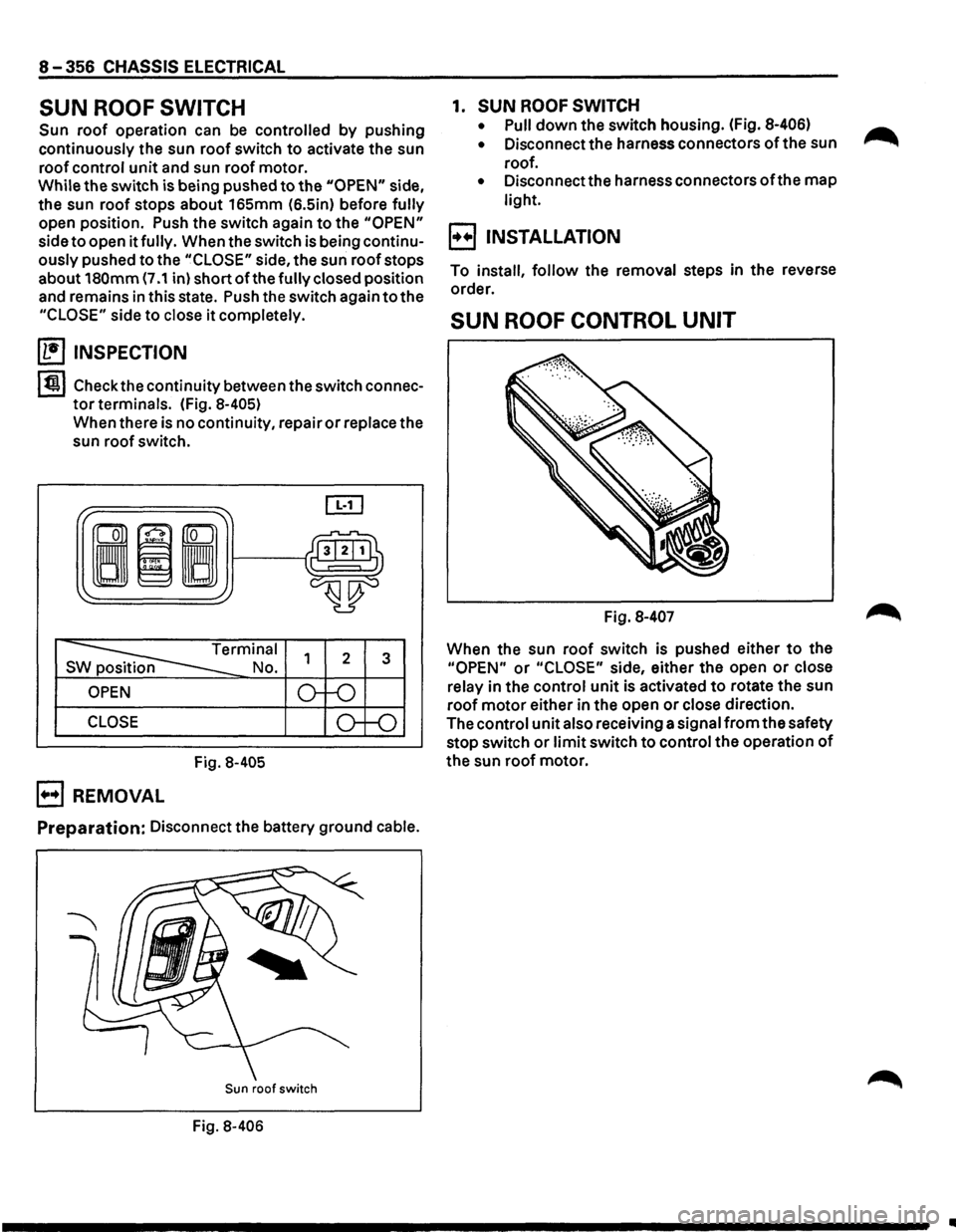
Sun roof operation can be controlled by pushing
continuously the sun
roof switch to activate the sun
roof control
unit and sun roof motor.
While the switch is being pushed
to the "OPEN" side,
the sun roof stops about 165mm (6.5in) before
fully
open position. Push the switch again to the "OPEN"
side to open it fully. When the switch is being continu
ously pushed to the
"CLOSE" side, the sun roof stops
about
180mm (7 .1 in) short ofthe fully closed position
and remains
in this state. Push the switch again to the
"CLOSE" side to close it completely.
~ INSPECTION
I tjt I Check the continuity between the switch connec
tor terminals. (Fig. 8-405)
When there is no continuity, repair or replace the
sun roof switch.
3
CLOSE
Fig. 8-405
E) REMOVAL
Preparation: Disconnect the battery ground cable.
Sun roof switch
Fig. 8-406
1. SUN ROOF SWITCH
• Pull down the switch housing. (Fig. 8-406)
•
Disconnect the harness connectors of the sun
roof.
• Disconnectthe harness connectors ofthe map
light.
E_3 INSTALLATION
To install, follow the removal steps in the reverse
order.
SUN ROOF CONTROL UNIT
Fig. 8-407
When the sun roof switch is pushed either to the
"OPEN" or "CLOSE" side, either the open or close
relay in the control
unit is activated to rotate the sun
roof motor either in the open or close direction.
The control unit also receiving a signal
from the safety
stop switch
or limit switch to control the operation of
the sun roof motor.
Page 1547 of 1928
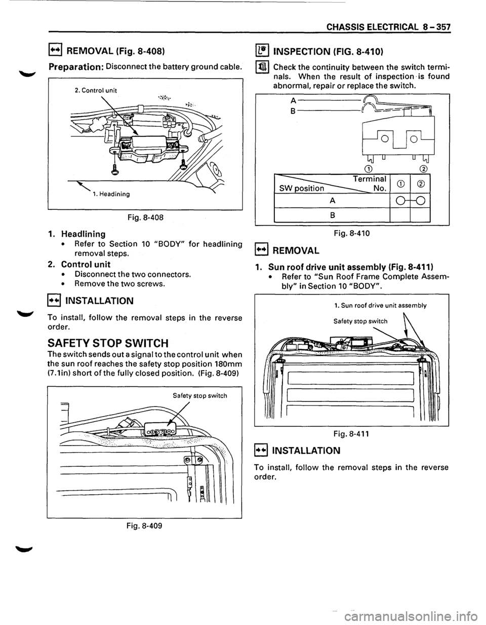
l+o+l REMOVAL (Fig. 8-408)
Preparation: Disconnect the battery ground cable.
2. Control unit
1. Headining
Fig. 8-408
1. Headlining
• Refer to Section 10 "BODY" for headlining
removal
steps.
2. Control unit
• Disconnect the two connectors.
• Remove the two screws.
EJ INSTALLATION
To install, follow the removal steps in the reverse
order.
SAFETY STOP SWITCH
The switch sends out a signal to the control unit when
the sun
roof reaches the safety stop position 180mm
(7 .1 in) short of the fully closed position. (Fig. 8-409)
Safety stop switch
Fig. 8-409
CHASSIS ELECTRICAL 8-357
~ INSPECTION (FIG. 8-410)
I tj I Check the continuity between the switch termi
nals. When the result of inspection· is found
abnormal, repair or replace the switch.
A-----
B------
B
Fig. 8-410
B REMOVAL
1. Sun roof drive unit assembly (fig. 8-411)
• Refer to "Sun Roof Frame Complete Assem
bly" in Section 10 "BODY".
1. Sun roof drive unit assembly
Fig. 8-411
B INSTALLATION
To install, follow the removal steps in the reverse
order.
Page 1548 of 1928
8-358 CHASSIS ELECTRICAL
LIMIT SWITCH
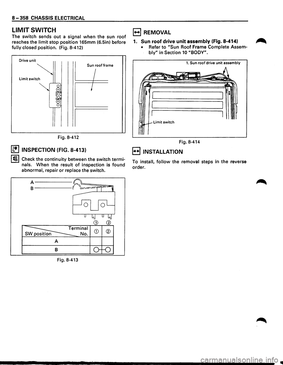
The switch sends out a signal when the sun roof
reaches the limit stop position 165mm (6.5in) before
fully closed position. (Fig. 8-412)
Drive unit
Sun roof frame
Limit switch
Fig. 8-412
(1!] INSPECTION (FIG. 8-413)
lt:il!l Check the continuity between the switch termi
nals. When the result of inspection is found
abnormal, repair or replace the switch.
A------
B------
A
B
Terminal
No.
Fig. 8-413
CD
B REMOVAL
1. Sun roof drive unit assembly (Fig. 8-414)
• Refer to "Sun Roof Frame Complete Assem
bly" in Section 10 "BODY".
1. Sun roof drive unit assembly
•. , ....... ,••1; .... , .. ·'··~~ /u
' f I R
I ~~============~,
I l
~
~~Limit switch
Fig. 8-414
B INSTALLATION
To install, follow the removal steps in the reverse
order.
..
Page 1549 of 1928
![ISUZU TROOPER 1995 Workshop Manual SUN ROOF MOTOR
~ INSPECTION
[]1]
I
~rminal
S p No.
Sun roof open side
Sun roof close side
Fig. 8-415 1
2
~ 8
8
~
Apply the battery voltage to the connector terminals
ofthe sun roof mo](/img/61/57183/w960_57183-1548.png "ISUZU TROOPER 1995 Workshop Manual SUN ROOF MOTOR
~ INSPECTION
[]1]
I
~rminal
S p No.
Sun roof open side
Sun roof close side
Fig. 8-415 1
2
~ 8
8
~
Apply the battery voltage to the connector terminals
ofthe sun roof mo")
SUN ROOF MOTOR
~ INSPECTION
[]1]
I
~rminal
S p No.
Sun roof open side
Sun roof close side
Fig. 8-415 1
2
~ 8
8
~
Apply the battery voltage to the connector terminals
ofthe sun roof motor to check its function (Fig. 8-415).
B REMOVAL (FIG. 8-416)
Preparation: Disconnect the battery ground cable.
2. Sun roof motor
1. Headlining
I
Fig.S-416
1. Headlining
• Refer to "Headlining" in Section 10 "Body".
2. Sun roof motor
• Disconnect the connector.
• Remove the three nuts and two screws.
E3 INSTALLATION
To install, follow the removal steps in the reverse
order.
CHASSIS ELECTRICAL 8-359
POWER WINDOW RELAY
(b!] INSPECTION
r·-----,
_..i___/ o----1..4> Q) I I
Fig. 8-417
lt!lll Check to see if there is continuity between the
relay terminals. (Fig. 8-417)
Replace
the relay when the result of inspection is
found abnormal.
®-@ ....... No Continuity
(When the battery voltage is applied between
CD-@)
®-@ ....... Continuity
NOTE:
For the relay removal, refer to "Connector Handling"
in the "NOTES FOR WORKING ON ELECTRICAL
ITEMS"
in this section.
Page 1550 of 1928
8-360 CHASSIS ElECTRICAl
POWER SEAT
GENERAL DESCRIPTION
The circuit consists of the power seat switch, front tilt motor (driver's seat only), rear tilt motor (driver's seat
only), slide motor and the recliner motor.
The power seat switch has a tilt & slide switch and a recliner switch. The motor built in the seat can be actuated
by operating these switches to move the seat to desired position, independent of the position of the starter
switch.
..