ISUZU TROOPER 1995 Workshop Manual
Manufacturer: ISUZU, Model Year: 1995, Model line: TROOPER, Model: ISUZU TROOPER 1995Pages: 1928
Page 1501 of 1928
CHASSIS ELECTRICAL 8-311
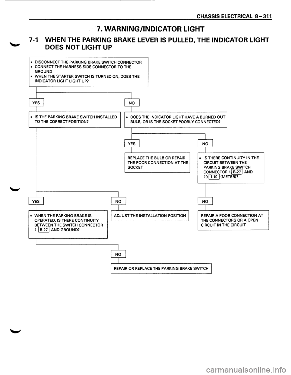
7. WARNING/INDICATOR LIGHT
7-1 WHEN THE PARKING BRAKE LEVER IS PULLED, THE INDICATOR LIGHT
DOES
NOT LIGHT UP
• DISCONNECT THE PARKING BRAKE SWITCH CONNECTOR • CONNECT THE HARNESS SIDE CONNECTOR TO THE GROUND
• WHEN THE STARTER SWITCH IS TURNED ON, DOES THE INDICATOR LIGHT LIGHT UP?
I
YES I NO I
I
• IS THE PARKING BRAKE SWITCH INSTALLED
• DOES THE INDICATOR LIGHT HAVE A BURNED OUT TO THE CORRECT POSITION? BULB, OR IS THE SOCKET POORLY CONNECTED?
I
I
YES I NO j
I
REPLACE THE BULB OR REPAIR • IS THERE CONTINUITY IN THE
THE POOR CONNECTION AT THE CIRCUIT BETWEEN THE
SOCKET PARKING BRAIE SWITCH CONNECTOR 1 B-27 AND
10 C8.QJ (METER)?
I
YES I I NO I NO I
I
• WHEN THE PARKING BRAKE IS I ADJUST THE INSTALLATION POSITION I REPAIR A POOR CONNECTION AT
OPERATED, IS THERE CONTINUITY THE CONNECTORS OR A OPEN
BETWEEN THE SWITCH CONNECTOR CIRCUIT IN THE CIRCUIT
1 I B-271 AND GROUND?
I
I NO I
I
I REPAIR OR REPLACE THE PARKING BRAKE SWITCH I
Page 1502 of 1928
8-312 CHASSIS ELECTRICAL
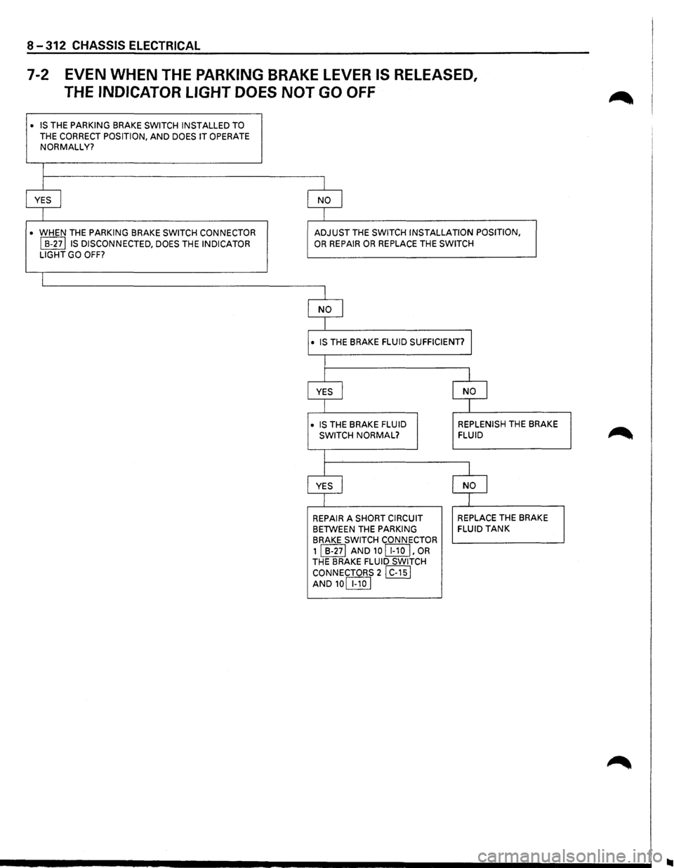
7-2 EVEN WHEN THE PARKING BRAKE LEVER IS RELEASED,
THE
INDICATOR LIGHT DOES NOT GO OFF
• IS THE PARKING BRAKE SWITCH INSTALLED TO
THE CORRECT POSITION, AND DOES IT OPERATE NORMALLY?
I
I I
YES I NO I
I I
• WHEN THE PARKING BRAKE SWITCH CONNECTOR ADJUST THE SWITCH INSTALLATION POSITION,
I B-27lls DISCONNECTED, DOES THE INDICATOR OR REPAIR OR REPLACE THE SWITCH
LIGHT GO
OFF?
I
I
NO I
I
• IS THE BRAKE FLUID SUFFICIENT? J
I
I I
YES I NO J
I
I
• IS THE BRAKE FLUID REPLENISH THE
BRAKE
SWITCH NORMAL? FLUID
I
I
l
YES I NO I
I I
REPAIR A SHORT CIRCUIT REPLACE THE
BRAKE
BETWEEN THE
PARKING FLUID TANK
BRAKE SWITCH
CONNECTOR
1 I B-271 AND 10 [I!QJ' OR THE BRAKE FLUID SWITCH
CONNECTORS
21 C-151 AND10[IlQ]
Page 1503 of 1928
CHASSIS ELECTRICAL 8-313
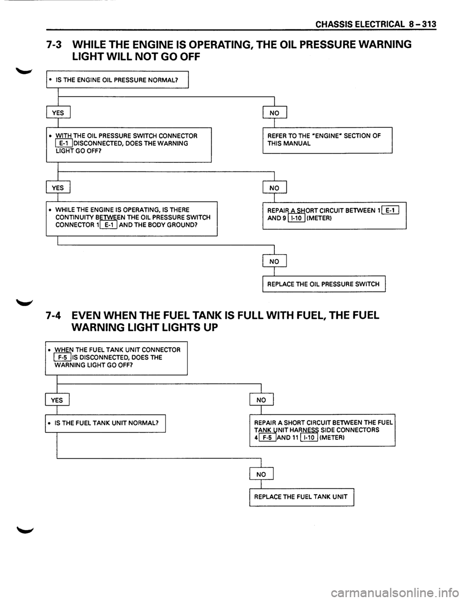
7-3 WHILE THE ENGINE IS OPERATING, THE OIL PRESSURE WARNING
LIGHT WILL
NOT GO OFF
• IS THE ENGINE OIL PRESSURE NORMAL? I
I
I I
YES I NO I
I I
• WITH THE OIL PRESSURE SWITCH CONNECTOR REFER TO THE "ENGINE" SECTION OF
~DISCONNECTED, DOES THE WARNING THIS MANUAL LIGHT GO OFF?
I
I I
YES I NO I
I I
• WHILE THE ENGINE IS OPERATING, IS THERE REPAIRctTIORT CIRCUIT BETWEEN 1 [ill CONTINUITY BETWEEN THE OIL PRESSURE SWITCH AND 9 1-10 (METER) CONNECTOR 1~ AND THE BODY GROUND?
I
I
NO I
I
REPLACE THE OIL PRESSURE SWITCH I
7-4 EVEN WHEN THE FUEL TANK IS FULL WITH FUEL, THE FUEL
WARNING LIGHT LIGHTS UP
• WHEN THE FUEL TANK UNIT CONNECTOR
[EIJ1s DISCONNECTED, DOES THE WARNING LIGHT GO OFF?
l
YES I NO I
I
• IS THE FUEL TANK UNIT NORMAL? I REPAIR A SHORT CIRCUIT BETWEEN THE FUEL
TiNK JNIT HARNESS SIDE CONNECTORS 4 F-5 AND 11 [I!QJ (METER)
1
NO I
I
REPLACE THE FUEL TANK UNIT I
Page 1504 of 1928
8-314 CHASSIS ELECTRICAL
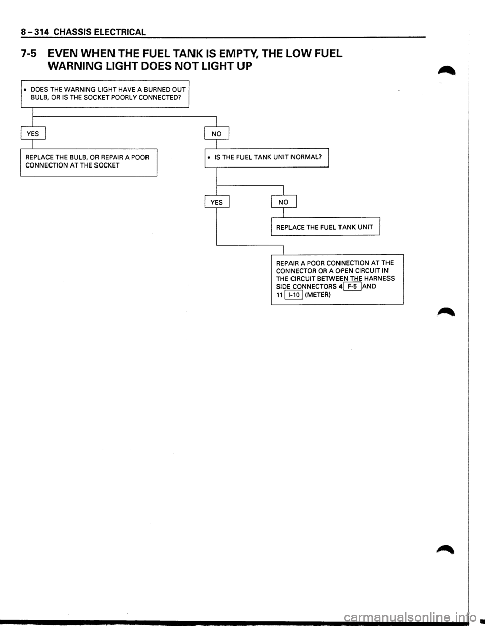
7-5 EVEN WHEN THE FUEL TANK IS EMPTY, THE LOW FUEL
WARNING LIGHT DOES NOT LIGHT UP
• DOES THE WARNING LIGHT HAVE A BURNED OUT
BULB, OR IS THE SOCKET POORLY CONNECTED?
I
I
YES I
I
REPLACE THE BULB, OR REPAIR A POOR
CONNECTION
AT THE SOCKET
I NO I
I· IS THE FUEL TANK UNIT NORMAL? I
I YES I
J
NO I
I
REPLACE THE FUEL TANK UNIT I
I
REPAIR A POOR CONNECTION AT THE CONNECTOR OR A OPEN CIRCUIT IN
THE CIRCUIT BETWEEN THE HARNESS
SIDE CONNECTORS
4[}IJAND 11 IT.IQJ (METER)
•
Page 1505 of 1928
STARTER SWITCH
Refer to "START AND CHARGING" in this section.
'--LIGHTING SWITCH/DIMMER •
PASSING SWITCH/HEADLIGHT
Refer to "HEADLIGHT AND FOG LIGHT" in this sec-
tion.
TURN SIGNAL SWITCH
Refer to "TURN SIGNAL LIGHT, HAZARD WARNING
LIGHT, CORNERING LIGHT, BACKUP LIGHT AND
HORN" in this section.
ILLUMINATION CONTROLLER
Refer to the "FRONT SIDE MARKER LIGHT, PARKING
LIGHT, TAILLIGHT, LICENSE PLATE LIGHT AND ILLU
MINATION LIGHT"
in this section.
CHASSIS ELECTRICAL 8-315
Page 1506 of 1928
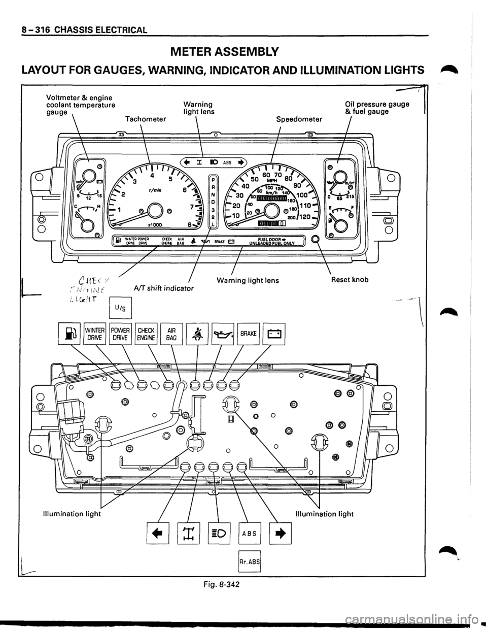
8-316 CHASSIS ELECTRICAL
METER ASSEMBLY
LAYOUT FOR GAUGES, WARNING, INDICATOR AND ILLUMINATION LIGHTS .~
L
Voltmeter & engine
coolant temperature
gauge
B
Warning light lens
0
ClEO< AIR Et.llf>E BAG
NT shift indicator
Fig. 8-342
@ @
0 0
Oil pressure gauge & fuel gauge
..
Page 1507 of 1928
CHASSIS ELECTRICAL 8-317
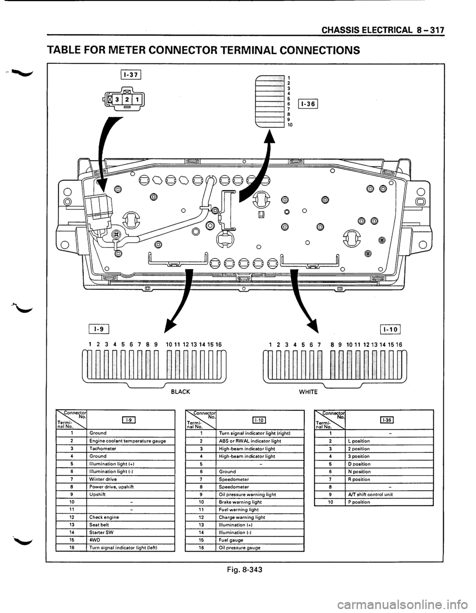
TABLE FOR METER CONNECTOR TERMINAL CONNECTIONS
~-""""""', 1----""'12 1----""'1! 6 1----l 6 [Iill
1----""'1 ~ 9 1---""'l,o
®
0 0
0
® @
0 0 ~
~m© © © © ©'--m ~~0
0 !III
1 2 3 4 5 6 7 8 9 1011 1213141516 1 2 3 4 56 7 8 9 10111213141516
w~~~~~~~~ ~~~~~~m rn~~~~~~ ~~nn~~m
~ I J BLACK WHITE
~r o. DTI -na No. ~
. IJJ:Q] -
. ~ [ill] . -. 1 Ground 1 Turn
signal indicator light (right)
1 -2 Engine coolant temperature gauge 2 ABS or RWAL indicator light 2 L
position
3 Tachometer 3 High-beam indicator light 3 2 position 4
Ground
4 High-beam
indicator light 4 3 position 6 Illumination light (+I 5 -5 D position
6 Illumination light(-) 6 Ground 6 N position 7 Winter drive 7 Speedometer 7 R position 8 Power drive, upshift 8 Speedometer 8 -9 Upshift 9 Oil pressure warning light 9 AfT shift control unit 10 -10 Brake warning light 10 P position 11 -11 Fuel warning light 12 Check engine 12 Charge warning light 13 Seat belt 13 Illumination (+) 14 StarterSW 14 Illumination (-) 15 4WD 15 Fuel gauge 16 Turn signal indicator light (left) 16 Oil pressure gauge
Fig. 8-343
Page 1508 of 1928
8-318 CHASSIS ELECTRICAL
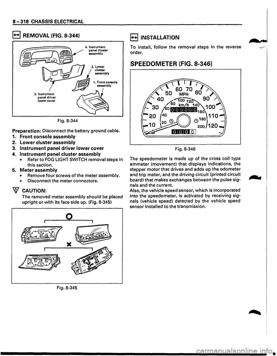
B REMOVAL (FIG. 8-344)
3. Instrument
panel driver lower cover
Fig. 8-344
4. Instrument
panel cluster
assembly
Preparation: Disconnect the battery ground cable.
1. Front console assembly
2. Lower cluster assembly
3. Instrument panel driver lower cover
4. Instrument panel cluster assembly
• Refer to FOG LIGHT SWITCH removal steps in
this section.
5. Meter assembly
• Remove four screws of the meter assembly.
•
Disconnect the meter connectors.
W CAUTION:
The removed meter assembly should be placed
upright or with its face side up. (Fig. 8-345)
0
)(
Fig. 8-345
B INSTALLATION
To install, follow the removal steps in the reverse
order.
SPEEDOMETER (FIG. 8-346)
Fig. 8-346
The speedometer is made up
of the cross coil type
ammeter (movement)
that displays indications, the
stepper
motor that drives and adds up the odometer
and
trip meter, and the driving circuit (printed circuit
board) that makes exchanges between the
pulse sig
nals and the current.
Also, the vehicle speed sensor, which is incorporated
into the speedometer, is activated
by receiving sig
nals (vehicle speed) detected by the vehicle speed
sensor
installed to the transmission.
•
Page 1509 of 1928
![ISUZU TROOPER 1995 Workshop Manual (1!] ON-VEHICLE SERVICE
"-"" Check the meter display accuracy and the operation
of the odometer with the speedometer tester.
\f CAUTION:
Inappropriate tire inflation may affect the accu
rac](/img/61/57183/w960_57183-1508.png "ISUZU TROOPER 1995 Workshop Manual (1!] ON-VEHICLE SERVICE
\"-\"\" Check the meter display accuracy and the operation
of the odometer with the speedometer tester.
\f CAUTION:
Inappropriate tire inflation may affect the accu
rac")
(1!] ON-VEHICLE SERVICE
"-"" Check the meter display accuracy and the operation
of the odometer with the speedometer tester.
\f CAUTION:
Inappropriate tire inflation may affect the accu
racy
of the odometer.
(To
conductthis test, refer to the tester manufac
turer's instruction manual.)
IGN GND
SEN
CHASSIS ELECTRICAL 8-319
(MPH)
Tester display speed Meter
display permissible
level
20 18.3-21.7
40 38.3-41.7
60 58.3-61.7
80 78.8-82.8
100 98.8-102.8
120 118.5-123.1
NOTE: Since the meter display permissible levels
above are specifications solely
for the
meter,
they are to be used as reference
values when conducting on-vehicle service.
~ INDIVIDUAL INSPECTION
I t!!.l Remove the speedometer from the meter
assembly and measure the resistance and the
current consumption between each terminal.
(Fig. 8-347)
Replace the speedometer
when the result of
inspection is found abnormal.
Resistance value
Red(+) Black(-) Black(-) Red(+)
IGN GND IGN GND IGN-GND 00 30.6-37.4k
SEN GND SEN GND SEN-GND 28.8-35.2k 00
4P GND 4P GND 4P-GND 13.5 -16.5k 00
Note: Use the
analog type circuit tester (range: x 1k)
Current value
Terminal
symbol
IGN-GND
~ 8
Current
consumption
85 ± 15mA Remarks
(when
12 ± 1V No signal input
applied)
Note: 1. Use the analog type circuit tester.
2. Since the current consumption fluctuates
when the source voltage varies, check
to
be sure that the voltage applied is 12V ± 1 V.
Fig. 8-347
Page 1510 of 1928
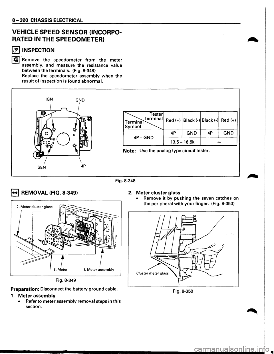
8-320 CHASSIS ELECTRICAL
VEHICLE SPEED SENSOR (INCORPO
RATED IN THE SPEEDOMETER)
~ INSPECTION
I tml Remove the speedometer from the meter
assembly, and measure the resistance value
between the terminals. (Fig. 8-348)
Replace the speedometer assembly
when the
result
of inspection is found abnormal.
IGN GND
SEN
Red(+) Black(-) Black(-) Red(+)
4P GND 4P GND
4P-GND 13.5-16.5k 00
Note: Use the analog type circuit tester.
Fig. 8-348
B REMOVAL (FIG. 8-349)
Fig. 8-349
Preparation: Disconnect the battery ground cable.
1.
Meter assembly
• Refer to meter assembly removal steps in this
section. 2.
Meter cluster glass
• Remove it by
pushing the seven catches on
the peripheral
with your finger. (Fig. 8-350)
Fig. 8-350
•