ISUZU TROOPER 1995 Workshop Manual
Manufacturer: ISUZU, Model Year: 1995, Model line: TROOPER, Model: ISUZU TROOPER 1995Pages: 1928
Page 1641 of 1928
'"""' Supplemental Restraint System 9J-17
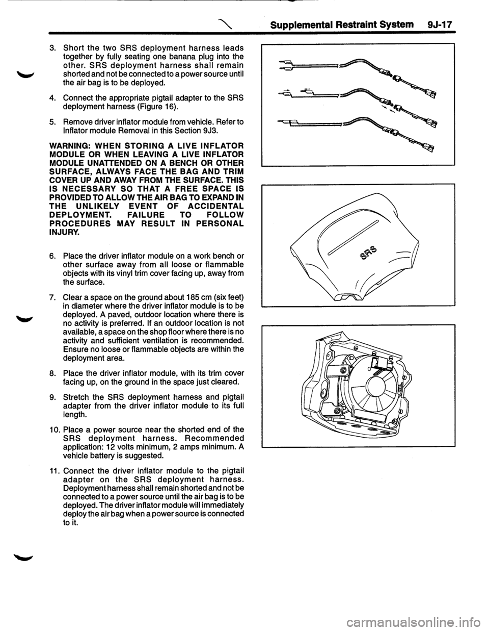
3. Short the two SRS deployment harness leads
together by fully seating one banana plug into the
other. SRS deployment harness shall remain
shorted and not be connected to a power source until
the air bag is to
be deployed.
4. Connect the appropriate pigtail adapter to the SRS
deployment harness (Figure 16).
5. Remove driver inflator module from vehicle. Refer to
Inflator module Removal in this Section 9J3.
WARNING: WHEN STORING A LIVE INFLATOR
MODULE OR
WHEN LEAVING A LIVE INFLATOR
MODULE
UNATTENDED ON A BENCH OR OTHER
SURFACE, ALWAYS FACE THE BAG AND TRIM
COVER
UP AND AWAY FROM THE SURFACE. THIS
IS NECESSARY SO THAT A FREE SPACE IS
PROVIDED TO ALLOW THE AIR BAG TO EXPAND IN
THE UNLIKELY EVENT OF ACCIDENTAL
DEPLOYMENT. FAILURE TO FOLLOW
PROCEDURES MAY RESULT IN PERSONAL
INJURY.
6. Place the driver inflator module on a work bench or
other surface away from all loose
or flammable
objects with its vinyl trim cover facing up, away from
the surface.
7. Clear a space on the ground about 185 em (six feet)
in diameter where the driver inflator module is to be
deployed.
A paved, outdoor location where there is
no activity is preferred.
If an outdoor location is not
available, a space
on the shop floor where there is no
activity and sufficient ventilation is recommended.
Ensure no loose or flammable objects are within the
deployment area.
8. Place the driver inflator module, with its trim cover
facing up,
on the ground in the space just cleared.
9. Stretch the SRS deployment harness and pigtail
adapter from the driver inflator module to its full
length.
10. Place a power source near the shorted end of the
SRS deployment harness. Recommended
application: 12 volts minimum, 2 amps minimum. A
vehicle battery is suggested.
11. Connect the driver inflator module to the pigtail
adapter on the SRS deployment harness.
Deployment harness shall remain shorted and not be
connected to a power source until the air bag is to be
deployed. The driver inflator module will immediately
deploy the air bag when a power source is connected
to
it.
Page 1642 of 1928
9J-18 Supplemental Restraint System
NOTE: Ensure that the pigtail adapter is firmly seated
into the driver inflator module connector. Failure to fully
seat the connectors may leave the shorting bar located
in the
driver inflator module connector functioning
(shorted) and may result
in non-deployment of the driver
inflator module.
12. Verify that the area around the driver inflator module
is clear of all people and loose or flammable objects.
13. Verify that the driver inflator module is resting with its
trim cover facing up.
14. Notify all people
in the immediate area that you
intend to deploy the driver inflator module. The
deployment will be accompanied by a loud noise
which may startle the uninformed.
15.
Separate the two banana plugs on the SRS
deployment harness.
NOTE: When the air bag deploys, the driver inflator
module may jump about
30 em (one foot) vertically. This
is a normal reaction of the driver inflator module to the
force of the rapid gas expansion inside the air bag.
NOTE: When the air bag deploys, the rapid gas
expansion will create a loud noise. Notify all people
in the
immediate area that you intend to deploy the driver
inflator module.
16. Connect the
SRS deployment harness wires to the
power source to immediately deploy the driver
inflator module. Recommended application: 12 volts
minimum, 2 amps minimum. A vehicle battery is
suggested.
17. Disconnect the
SRS deployment harness from the
power source.
18.
Short the two SRS deployment harness leads
together by fully seating one banana plug into the
other.
19.
In the unlikely event that the driver inflator module did
not deploy after following these procedures, proceed
immediately with
Steps 24 through 27. If the driver
inflator module did deploy, proceed with
Steps 20
through 23.
20. Put on a pair of shop gloves to protect your hands
from possible irritation and heat when handling the
deployed driver inflator module.After the driver
inflator module has been deployed, the surface of the
air bag may contain a powdery residue. This power
consists primarily of cornstarch(used to lubricate the
bag as it inflates) and byproducts of the chemical
reaction.
Sodium hydroxide dust( similar to lye soap)
is produced as a byproduct
of the deployment
reaction.The sodium hydroxide then quickly reacts
with the atmospheric moisture and is converted to
sodium carbonate and sodium bicarbonate(baking
soda). Therefore, it is unlikely that sodium hydroxide
will be present after deployment. As a precaution,
however, gloves and safely glasses are
recommended to prevent any possible irritation of
the skin or eyes.
WARNING: SAFETY PRECAUTIONS MUST BE
OBSERVED WHEN
HANDING A DEPLOYED
INFLATOR MODULE. AFTER DEPLOYMENT, THE ~
METAL SURFACES OF THE INFLATOR MODULE
WILL BE VERY HOT. ALLOW THE INFLATOR
MODULE TO COOL BEFORE HANDLING ANY
METAL PORTION OF IT. DO NOT PLACE THE
DEPLOYED
INFLATOR MODULE NEAR ANY
FLAMMABLE OBJECTS.
FAILURE TO FOLLOW
PROCEDURES MAY RESULT
IN FIRE OR
PERSONAL INJURY.
After a driver inflator module has been deployed, the
metal canister and surrounding areas
of the driver
inflator module will
be very hot. Do not touch the metal
areas of the driver inflator module for about twenty
minutes after deployment.
If the deployed driver inflator
module must
be moved before it is cool, wear gloves and
handle by the air bag or trim cover.
21. Disconnect the pigtail adapter from the driver inflator
module as soon after deployment as possible. This
will prevent damage to the pigtail adapter or
SRS
deployment harness due to possible contact with the
hot driver inflator module canister. The pigtail can be
reused. They should, however, be inspected for
damage after each deployment and replaced if
necessary.
22. Dispose of the deployed driver inflator module
through normal refuse channels after it has cooled
for at least
20 minutes. ~
23. Wash your hands with mild soap and water
afterward.
NOTE: The remaining steps are to be followed in the
unlikely event that the driver inflator module did not
deploy after following these procedures.
24. Ensure that the
SRS deployment harness has been
disconnected from the power source and that its two
banana plugs have been shorted together by fully
seating one banana plug into the other.
25. Disconnect the pigtail
adapter from the driver inflator
module.
WARNING: WHEN STORING A LIVE INFLATOR
MODULE OR WHEN LEAVING A LIVE INFLATOR
MODULE UNATTENDED ON A BENCH OR OTHER
SURFACE, ALWAYS FACE THE BAG AND
TRIM
COVER
UP AND AWAY FROM THE SURFACE. THIS
IS
NECESSARY SO THAT A FREE SPACE
ISRPROVIDED TO ALLOW THE AIR BAG TO
EXPAND IN THE UNLIKELY EVENT OF ACCIDENTAL
DEPLOYMENT. FAILURE TO FOLLOW
PROCEDURES MAY RESULT IN PERSONAL
INJURY.
•
Page 1643 of 1928
~ Supplemental Restraint System 9J-19
26. Temporarily store the driver inflator module with its inflator module can be found in the applicable service
vinyl trim cover facing
up, away from the surface manual or in a service bulletin.
upon which is rests.
27.
Call the Technical Assistance group for further
assistance.
DEPLOYMENT OUTSIDE VEHICLE
(PASSENGER INFLATOR MODULE)
WARNING: FAILURE TO FOLLOW PROPER SRS
INFLATOR MODULE DISPOSAL PROCEDURES
CAN RESULT IN AIR BAG DEPLOYMENT WHICH
MAY CAUSE PERSONAL INJURY. UNDEPLOYED
INFLATOR MODULES MUST NOT BE DISPOSED OF
THROUGH NORMAL REFUSE CHANNELS. THE
UNDEPLOYED INFLATOR MODULE CONTAINS
SUBSTANCES
THAT CAN CAUSE SEVERE ILLNESS
OR
PERSONAL INJURY IF THE SEALED
CONTAINER IS DAMAGED DURING DISPOSAL.
DISPOSAL
IN ANY MANNER INCONSISTENT WITH
PROPER PROCEDURES MAY BE A VIOLATION OF
FEDERAL, STATE AND/OR LOCALLAWS.
Deployment out of the vehicle is proper when the vehicle
is to be returned to service. This includes, for example,
situations
in which a functionally or cosmetically deficient
inflator module
is replaced. Deployment and disposal of
an inflator module is, of course, subject to any required
reterntion period.
For deployment
of a live inflator module out of the
·'-" vehicle, the deployment procedure must be followed
exactly.
ALWAYS wear safety glasses during this
deployment procedure until the deployed inflator module
is scrapped. Before performing the procedures you
should
be familiar with servicing the SRS system and
with proper handling of the inflator module. Procedures
should be read fully before they are performed.
The following procedure requires use of J-41434
SIR
Deployment Harness with the appropriate pigtail
adapter. The procedure also requires the use of J-41497
Passenger
Side SRS Module Deployment Fixture. Do
not attempt this procedure without J-41434 and adapter,
and J-41497.
WARNING: FAILURE TO FOLLOW PROCEDURES
IN THE ORDER LISTED MAY RESULT IN PERSONAL
INJURY.
NEVER CONNECT DEPLOYMENT
HARNESS TO ANY POWER SOURCE BEFORE
CONNECTING DEPLOYMENT HARNESS TO THE
INFLATOR MODULE. DEPLOYMENT HARNESS
SHALL REMAIN SHORTED AND NOT BE
CONNECTED TO A POWER SOURCE UNTIL THE
AIRBAG IS TO BE DEPLOYED. THE INFLATOR
MODULE WILL IMMEDIATELY DEPLOY THE
AIRBAG WHEN A POWER SOURCE IS CONNECTED
TO IT. WEAR SAFETY GLASSES THROUGHOUT
THIS ENTIRE DEPLOYMENT AND DISPOSAL
~ PROCEDURE.
NOTE: This information applies only to passenger
inflator modules. Information for disposing of a live driver
1. Turn ignition switch to "LOCK", remove key, and put
on safety glasses.
2. Inspect J-41434 SRS Deployment Harness and
appropriate pigtail adapter for damage.
If harness or
pigtail is damaged, discard and obtain a
replacement.
Page 1644 of 1928
9J-20 Supplemental Restraint SysteA
~----------------------------------~
--
=======C.pp=::::J
============~~ 'r;;;;r=
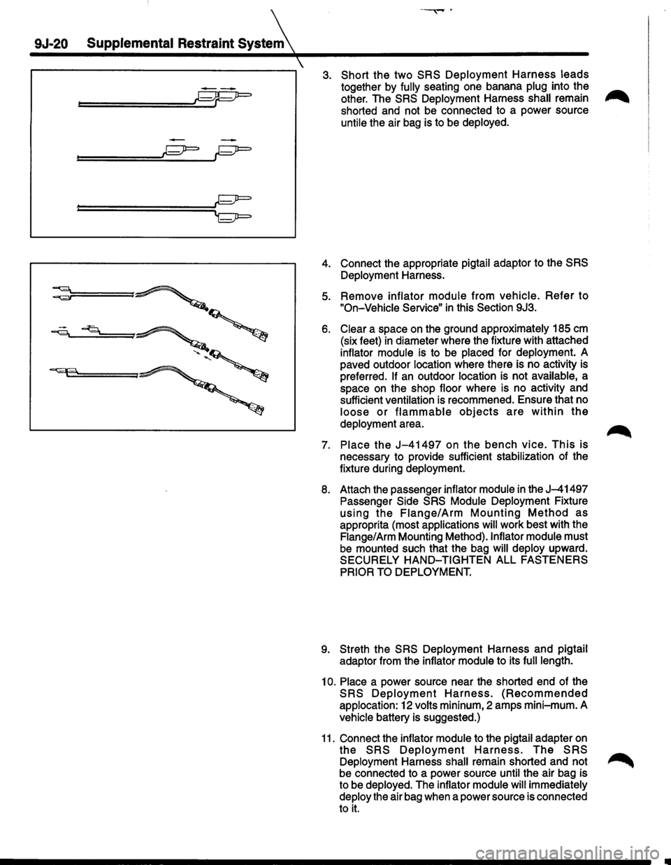
3. Short the two SRS Deployment Harness leads
together by fully seating one banana plug into the ..-.,.
other. The SRS Deployment Harness shall remain ,..,......
shorted and not be connected to a power source
untile the air bag is to be deployed.
4. Connect the appropriate pigtail adaptor to the SRS
Deployment Harness.
5. Remove inflator module from vehicle. Refer to
"On-Vehicle Service" in this Section 9J3.
6. Clear a space on the ground approximately 185 em
(six feet) in diameter where the fixture with attached
inflator module is to be placed for deployment. A
paved outdoor location where there is no activity is
preferred.
If an outdoor location is not available, a
space on the shop floor where is no activity and
sufficient ventilation is recommened. Ensure that no
loose or flammable objects are within the
deployment area.
7. Place the J-41497 on the bench vice. This is
necessary to provide sufficient stabilization of the
fixture during deployment.
8. Attach the passenger inflator module in the J-41497
Passenger Side SRS Module Deployment Fixture
using the Flange/Arm Mounting Method as
approprita (most applications will work best with the
Flange/Arm Mounting Method).lnflator module must
be mounted such that the bag will deploy upward.
SECURELY
HAND-TIGHTEN ALL FASTENERS
PRIOR TO DEPLOYMENT.
9. Streth the SRS Deployment Harness and pigtail
adaptor from the inflator module to its
full length.
10. Place a power source near the shorted end of the
SRS Deployment Harness. (Recommended
applocation: 12 volts mininum, 2 amps mini-mum. A
vehicle battery is suggested.)
11. Connect the inflator module to the pigtail adapter on
the SRS Deployment Harness. The SRS
Deployment Harness shall remain shorted and not ~
be connected to a power source until the air bag is
to be deployed. The inflator module
will immediately
deploy the air bag when a power source is connected
to it.
Page 1645 of 1928
WARNING: ENSURE THAT THE PIGTAIL ADAPTOR
IS FIRMLY SEATED INTO THE INFLATOR MODULE
CONNECTOR. FAILURE TO FULLY SEAT THE
CONNECTORS MAY LEAVE THE SHORTING BAR
LOCATED IN THE INFLATOR MODULE
CONNECTOR FUNCTIONING (SHORTING THE
DEPLOYMENT CIRCUIT) AND MAY RESULT IN
NONDEPLOYMENT OF THE INFLATOR MODULE.
12.
Verify that the area around the inflator module is clear
of all people and loose or flammable objects.
13.
Verify that the inflator module is firmly and properly
in J-41497.
14. Notify
all people in the immediate area of your
intention to deploy the inflator module. The
deployment will be accompanied by a substantial
noise which may startle the uninformed.
15.
Separate the two banana plugs on the SRS
Deployment Harness that were shorted together in
Step 3.
NOTE: When air bag depolys, the rapid gas
expansion will create a substantial noise. Notify all
people in the immediate area that you intend to deploy
the inflator module.
WARNING: DEPLOYMENT HARNESS SHELL
REMAIN SHORTED AND NOT BE CONNECTED TO A
POWER SOURCE UNTIL THE AIR BAG IN TO BE
DEPLOYED. THE INFLATOR MODULE WILL
IMMEDIATELY DEPLOY THE AIR BAG WHEN A
POWER SOURCE IS CONNECTED TO IT.
CONNECTING
THE DEPLOYMENT HARNESS TO
THE POWER SOURCE SHOULD ALWAYS BE THE
LAST STEP IN THE INFLATOR MODULE
DEPLOYMENT PROCEDURE. FAILURE TO
FOLLOW PROCEDURES IN THE ORDER LISTED
MAY RESULT IN PERSONAL INJURY.
16. Connect the SRS Deployment Harness wires to the
power source to immediately deploy the inflator
module.
17. Disconnect the
SRS Deployment Harness from the
power source.
18.
Short the two SRS Deployment Harness leads
together by fully seating one banana plug into the
other.
19.
In the unlikely event that the inflator module did not
deploy after following these procedures, proceed
immediately with
Steps 24 through 27. If the inflator
module deployed
as intended, proceed with Steps 20
through 23.
20. Put on a pair of shop gloves to protect your hands
from possible irritation and heat when handling the
deployed inflator module. After the inflator module
has been deployed, the surface of the air bag may
contain a powdery residue. This powder consists
primarily of cornstarch (used to lubricate the bag as
it inflates) and byproducts of the chemical reaction.
Supplemental Restraint System 9J-21
Sodium hydroxide dust (similar to lye soap) is
produced as a byproduct of the deployment reaction.
The sodium hydroxide quickly reacts with the
atmospheric moisture and is convertered to sodium
carbonate and sodium bicarbonate (baking soda).
Therefore, it is unlikely that sodium hydroxide will
be
present for very long after deplyment. As a
precaution, however, gloves and safety glasses are
recommended to prevent any possible irritation of
the skin or eyes.
WARNING: SAFETY PRECAUTIONS MUST BE
OBSERVED WHEN HANDLING A DEPLOYED
INFLATOR MODULE. AFTER DEPLOYMENT, THE
METAL
SURFACES OF THE INFLATOR MODULE
WILL BE HOT. ALLOW THE INFLATOR MODULE TO
COOL
BEFORE HANDLING ANY METAL PORTION
OF
IT. DO NOT PLACE THE DEPLOYED INFLATOR
MODULE NEAR ANY FLAMMABLE OBJECTS.
FAILURE TO FOLLOW PROCEDURES MAY RESULT
IN FIRE OR PERSONAL INJURY.
AFTER AN INFLATOR MODULE HAS BEEN
DEPLOYED, THE METAL CANISTER AND
SURROUDING AREAS OF THE INFLATOR MODULE
WILL BE HOT. DO NOT TOUCH THE METAL AREAS
OF
THE INFLATOR MODULE FOR ABORT TWENTY
MINUTES AFTER DEPLOYMENT. IF THE DEPLOYED
INFLATOR MODULE MUST BE MOVED BEFORE IT
IS COOL,
WEAR GLOVES AND HANDLE BY THE AIR
BAG ITSELF.
21. Disconnect the pigtail adapter from the inflator
module as soon after deployment as possible to
avoid damage to the pigtail adaptor or SRS
Deployment Harness from contacting the hot inflator
module canister. The pigtail adapter and SIR
Deployment Harness are designed to be reused.
They should, however, be inspected for damage
after each deployment and replaced if necessary.
22. Dispose
of the deployed inflator module trough
normal refuse channels afterit has cooled for at least
20 minutes.
23. Wash
your hands with mild soap and water
afterward.
NOTE: The remaining steps are to be followed in the
unlikely event that the inflator module did not deploy after
following the above procedures.
24. Ensure that the
SRS Deplyment Harness has been
disconnected from the the power source and that its
two banana plugs have been shorted together by
fully seating one banana plug into the other.
25. Disconnect the pigtail adapter from the inflator
module.
WARNING: WHEN STORING A LIVE INFLATOR
MODULE OR WHEN LEAVING A LIVE INFLATOR
MODULE UNATTENDED ON A BENCH OR OTHER
SURFACE, ALWAYS
FACE THE BAG UP AND AWAY
FROM THE SURFACE. THIS IS NECESSARY SO
THAT A FREE SPACE IS PROVIDED TO ALLOW THE
Page 1646 of 1928
9J-22 Supplemental Restraint System
AIR BAG TO EXPAND IN THE UNLIKELY EVENT OF
ACCEIDENTAL DEPLOYMENT. FAILURE TO
FOLLOW PROCEDURES MAY RESULT IN
PERSONAL INJURY.
26. Temporarily store the inflator module with the bag
facing up, away from the surface upon which it rests.
27.
Call the Technical Assistance group for further
assistance.
DEPLOYMENT INSIDE VEHICLE(VEHICLE
SCRAPPING PROCEDURE)
Deployment inside vehicle is proper when the vehicle is
to be destroyed or
salvaged for component parts. This
includes, but is not limited to, the following situations.
1. The vehicle has completed its useful life.
2. The vehicle has been damaged beyond repair in a
non-deployment type accident.
3. The vehicle has been stripped or damaged beyond
repair
in a theft.
4. The vehicle will be salvaged for component parts to
be
used on a vehicle with a different Vehicle
Identification Number (VIN) as opposed to being
rebuilt as same VIN. Never use SRS components
from another
vehicle. This is done to ensure SRS
system integrity since only new SRS system
components.
WARNING: FAILURE TO FOLLOW PROPER SRS
INFLATOR MODULE DISPOSAL PROCEDURES
CAN RESULT IN AIR BAG DEPLOYMENT WHICH
MAY CAUSE PERSONAL INJURY. UNDEPLOYED
INFLATOR MODULES MUST NOT BE DISPOSED OF
THROUGH NORMAL REFUSE CHANNELS. THE
UNDEPLOYED INFLATOR MODULE CONTAINS
SUBSTANCES THAT CAL CAUSE SEVERE ILLNESS
OR
PERSONAL INJURY IF THE SEALED
CONTAINER IS DAMAGED DURING DISPOSAL.
DISPOSAL IN ANY MANNER INCONSISTENT WITH
PROPER PROCEDURES MAY BE A VIOLATION OF
FEDERAL, STATE AND/OR LOCAL LAWS.
1. Turn ignition switch to "LOCK," remove key and put
on safety glasses.
2. Remove all loose objects from front seats.
3. Disconnect driver inflator module, yellow 3-way
connector located at the base of the steering column.
4. Cut the driver inflator module yellow 2-way harness
connector from the
vehicle leaving at least 16 cm(six
inches) of wire at the connector.
5. Strip 13 mm(1/2 inch) of insulation from each wire
lead of the connector.
6. Cut two 900 cm(30 feet) deployment wires from
0.8mm2(18 gauge) or thicker
multi-strand wire. These
wires
will be used to fabricate the driver
deployment harness.
7. Strip 13 mm(1/2 inch) of insulation from both ends of
the wires cut
in the previous step.
8. Short the wires by twisting together one end from
each. Deployment wires
shall remain shorted and
not
be connected to a power source until the air bag
is to be
deployed.
WARNING: FAILURE TO
FOLLOW PROCEDURES
IN
THE ORDER LISTED COULD RESULT IN
PERSONAL INJURY. NEVER CONNECT
DEPLOYMENT WIRES TO ANY POWER SOURCE
BEFORE CONNECTING DEPLOYMENT WIRES TO
THE INFLATOR MODULE LEADS. DEPLOYMENT
WIRES SHALL REMAIN SHORTED AND NOT BE
CONNECTED TO A POWER SOURCE UNTIL THE
AIR BAG IS TO BE DEPLOYED. THE INFLATOR
MODULE WILL IMMEDIATELY DEPLOY THE AIR
BAG WHEN A POWER SOURCE IS CONNECTED TO
IT. WEAR SAFETY GLASSES THROUGHOUT THIS
ENTIRE DEPLOYMENT AND DISPOSAL
PROCEDURE.
9. Twist together one connector wire lead to one
deployment wire. The connection should be
mechanically secure.
10. Bend twisted connection made in the previous step
flat and wrap tightly with electrical tape to insulate ~
and secure.
11. Twist together, bend and tape the remaining
connector wire lead to the remaining deployment
wire.
12. Connect the deployment harness to the driver
inflator module, yellow 2-way connector at the base
of the steering
column. Route deployment harness
out the driver side of the
vehicle.
WARNING:
DEPLOYMENT WIRES SHALL REMAIN
SHORTED
AND NOT BE CONNECTED TO A POWER
SOURCE UNTIL THE AIR BAG IS TO BE DEPLOYED.
THE INFLATOR MODULE WILL IMMEDIATELY
DEPLOY THE AIR BAG WHEN A POWER SOURCE IS
CONNECTED TO IT.
CONNECTING THE DEPLOYMENT WIRES TO THE
POWER
SOURCE SHOULD ALWAYS BE THE FINAL
STEP IN
THE INFLATOR MODULE DEPLOYMENT
PROCEDURE. FAILURE TO FOLLOW
PROCEDURES IN THE ORDER LISTED COULD
RESULT IN PERSONAL INJURY.
13. Disconnect passenger inflator module, yellow 2-way
connector located behind 1/P compartment door
assembly.
14. Cut the passenger inflator module harness
connector from the vehicle leaving at least 16 cm(six
inches) of wire at the connector).
Page 1647 of 1928
15. Strip 13 mm(1/2 inch) of insulation from each wire
lead of the connector.
16.
Cut two 900 cm(30 feet) deployment wires from
0.8mm2(18 gauge) or thicker multi-strand wire.
These wires
will be used to fabricate the passenger
deployment harness.
17.
Strip 13 mm {1/2inch)of insulation from both ends of
the wires cut in the previous step.
18.
Short the wires by twisting together one end from
each.
Deployment wires shall remain shorted and
not be connected to a power source
until the air bag
is to be deployed.
WARNING: FAILURE TO FOLLOW
PROCEDURES
IN THE ORDER LISTED COULD RESULT IN
PERSONAL INJURY. NEVER CONNECT
DEPLOYMENT WIRES TO ANY POWER SOURCE
BEFORE CONNECTING DEPLOYMENT WIRES TO
THE INFLATOR MODULE LEADS. DEPLOYMENT
WIRES SHALL REMAIN SHORTED AND NOT BE
CONNECTED TO A POWER SOURCE UNTIL THE
AIR BAG IS DEPLOYED? THE INFLATOR MODULE
WILL IMMEDIATELY DEPLOY THE AIR BAG WHEN
A POWER
SOURCE IS CONNECTED TO IT. WEAR
SAFETY GLASSES THROUGHOUT THIS ENTIRE
DEPLOYMENT AND DISPOSAL PROCEDURE.
19. Twist
together one connector wire lead to one
deployment wire. The connection should be
mechanically secure.
20. Bend twisted connection made in the previous step
flat and wrap tightly with electrical tape to insulate
and secure.
21.
Twist together, bend and tape the remaining
connector wire lead to the remaining deployment
wire.
22. Connect the
deployment harness to the passenger
inflator module jumper, yellow 2-way connector
located behind the 1/P compartment door assembly.
Route deployment harness out the passenger side of
the
vehicle.
WARNING:
DEPLOYMENT WIRES SHALL REMAIN
SHORTED
AND NOT BE CONNECTED TO A POWER
SOURCE UNTIL THE AIR BAG IS TO BE DEPLOYED.
THE INFLATOR MODULE WILL IMMEDIATELY
DEPLOY THE AIR BAG WHEN A POWER SOURCE IS
CONNECTED TO IT. CONNECTING THE
DEPLOYMENT WIRES SHOULD ALWAYS BE THE
FINAL STEP IN THE INFLATOR MODULE
DEPLOYMENT PROCEDURE. FAILURE TO
FOLLOW PROCEDURES IN THE ORDER LISTED
COULD RESULT IN PERSONAL INJURY.
23. Verify that the inside of the vehicle and the area
surrounding the
vehicle are clear of all people and
loose or flammable objects.
24.
Stretch the driver and passenger deployment
harnesses to their full length.
Supplemental Restraint System 9J-23
. Completely cover windshield area and front door
window openings with a drop
cloth, blanket or similar
item. This reduced the possibility of injury due to
possible fragmentation of the vehicle's glass or
interior.
26. Notify
all people in the immediate area that you
intend to
deploy the air bags. The deployment will be
accompanied by a
loud noise which may startle the
uninformed.
27.
Separate the two ends of the driver deployment
harness wires.
WARNING: DEPLOYMENT WIRES SHALL REMAIN
SHORTED
AND NOT BE CONNECTED TO A POWER
SOURCE UNTIL THE AIR BAG IS TO BE DEPLOYED.
THE INFLATOR MODULE WILL IMMEDIATELY
DEPLOY THE AIR BAG WHEN A POWER SOURCE IS
CONNECTED TO IT. CONNECTING THE
DEPLOYMENT WIRES TO THE POWER SOURCE
SHOULD ALWAYS BE THE FINAL STEP IN THE
INFLATOR MODUL,E DEPLOYMENT PROCEDURE.
FAILURE TO FOLLOW PROCEDURES IN THE
ORDER LISTED COULD RESULT IN PERSONAL
INJURY.
NOTE: When the air bag deploys, the rapid gas
expansion will create a loud noise. Notify all people in the
immediate area that you intend to
deploy the air bags.
28. Connect the driver
deployment harness wires to a
power source to immediately deploy the driver
inflator module. Recommended application: 12 volts
minimum, 2 amps minimum. A vehicle battery is
suggested.
29.
Separate the two ends of the passenger deployment
harness wires.
WARNING: DEPLOYMENT WIRES SHALL REMAIN
SHORTED
AND NOT BE CONNECTED TO A POWER
SOURCE UNTIL THE AIR BAG IS TO BE DEPLOYED.
THE INFLATOR MODULE WILL IMMEDIATELY
DEPLOY THE AIR BAG WHEN A POWER SOURCE IS
CONNECTED TO IT. CONNECTING THE
DEPLOYMENT WIRES TO THE POWER SOURCE
SHOULD ALWAYS BE THE FINAL STEP IN THE
INFLATOR MODULE DEPLOYMENT PROCEDURE.
FAILURE TO FOLLOW PROCEDURES IN THE
ORDER LISTED COULD RESULT IN PERSONAL
INJURY.
30.
Connectthe passenger deployment harness wires to
a power source to
immediately deploy the passenger
inflator module. Recommended application: 12 volts
minimum, 2 amps minimum. A vehicle battery is
suggested.
After
an inflator module has been deployed, the
surface of the air bag may contain a powdery
residue. This powder consists primarily of cornstarch
(used to lubricate the bag as it inflates) and
byproducts of the chemical reaction. Sodium
hydroxide dust (similar to lye soap) is produced as a
byproduct of the
deployment reaction. The sodium
Page 1648 of 1928
9J-24 Supplemental Restraint System
hy~roxide th~n quickly reacts with atmospheriC' PROCEDURES COULD RESULT IN PERSONAL
mo1sture and IS converted to sodium carbonate and INJURY.
so~ium bicarbonate (baking soda). Therefore, it is
unlikely that sodium hydroxide will be present after
deployment.
As a precaution, however, gloves and
safety glasses are recommended to prevent any
possible irritation of the skin or eyes.
WARNING: SAFETY PRECAUTIONS MUST BE
OBSERVED WHEN HANDLING A DEPLOYED
INFLATOR MODULE. AFTER DEPLOYMENT, THE
METAL
SURFACES OF THE INFLATOR MODULE
WILL BE VERY HOT. ALLOW THE INFLATOR
MODULE TO COOL BEFORE HANDLING ANY
METAL PORTION OF IT. DO NOT PLACE THE HOT
DEPLOYED INFLATOR MODULE NEAR ANY
FLAMMABLE OBJECTS. FAILURE TO FOLLOW
PROCEDURES COULD RESULT IN FIRE OR
PERSONAL INJURY.
After an inflator module has been deployed, the metal
canister and surrounding areas of the inflator module will
be very hot. Do not touch the metal areas of the inflator
module for about
10 minutes after deployment. If the
deployed inflator module must be moved before it
is cool,
wear gloves
and handle by the air bag or vinyl trim.
31. S~o~t the driver deployment harness wires by
tw1st1ng together one end from each. Repeat this
procedure for the passenger deployment harness.
32. Carefully remove drop cloth from vehicle and clean
off any fragments or discard drop cloth entirely.
33. Disconnect driver deployment harness and
passenger deployment harness from vehicle and
discard.
34.
In the unlikely event that either or both of the inflator
modules did not deploy after following these
procedures, proceed immediately with Steps 36
through
38. If the inflator module deployed proceed
step
35.
35. With both air bags deployed, the vehicle may be
scrapped in the same manner as a non-SRS
equipped vehicle.
NOTE: The remaining steps are to be followed in the
unlikely event that the inflator module did not deploy otter
following these procedures.
36. Remove the undeployed inflator module(s) from the
vehicle. For driver inflator module refer to
in this
section for passenger inflator module
"On-Vehicle
Service".
WARNING:
WHEN STORING A LIVE INFLATOR
MODULE OR WHEN LEAVING A LIVE INFLATOR
MODULE
UNATTENDED ON A BENCH OR OTHER
SURFACE, ALWAYS FACE THE BAG AND TRIM
COVER
UP, AWAY FROM THE SURFACE. THIS IS
NECESSARY SO THAT A FREE SPACE IS
PROVIDED
TO ALLOW THE AIR BAG TO EXPAND IN
THE UNLIKELY EVENT OF ACCIDENTAL
DEPLOYMENT. FAILURE TO FOLLOW
37. Temporarily store the inflator module with the air bag
opening facing
up, away from the surface upon which
it rests.
38. Call the Technical Assistance group for further
assistance.
DEPLOYED INFLATOR MODULE HANDLING
After the inflator module has been deployed, the surface
of the air bag may contain a powdery residue. This
powder
consists primarily of cornstarch (used to
lubricate the bag as it inflates) and byproducts of the
chemical reaction.
Sodium hydroxide dust (similar to lye
soap)
is produced as a byproduct of the deployment
reaction. The sodium hydroxide then quickly reacts with
atmospheric moisture and is converted
to sodium
carbonate and sodium bicarbonate (baking soda}.
Therefore, it
is unlikely that sodium hydroxide will be
present after deployment. As with many service
procedures, you should wear gloves and safety glasses.
Page 1649 of 1928
, Supplem~l Restraint System
SPECIAL TOOLS
WARNING: TO AVOID DEPLOYMENT WHEN
'-' TROUBLESHOOTING THE SRS, DO NOT USE
ELECTRICAL TEST EQUIPMENT SUCH AS A
BATTERY-POWERED OR AC-POWERED
VOLTMETER, OHMMETER, ETC., OR ANY TYPE OF
ELECTRICAL EQUIPMENT OTHER THAN THAT
SPECIFIED IN THIS MANUAL. DO NOT USE A
NON-POWERED PROBE TYPE TESTER.
INSTRUCTIONS IN THIS MANUAL MUST BE
FOLLOWED CAREFULLY, OTHERWISE PERSONAL
INJURY
MAY RESULT.
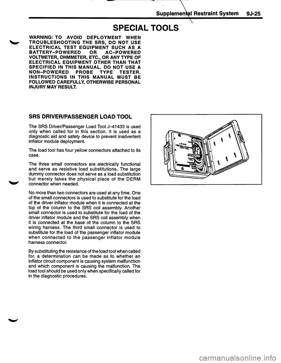
SRS DRIVER/PASSENGER LOAD TOOL
The SRS Driver/Passenger Load Tool J-41433 is used
only when called for in this section. It is used as a
diagnostic aid and safety device to prevent inadvertent
inflator
module deployment.
The
load tool has four yellow connectors attached to its
case.
The three
small connectors are electrically functional
and serve as resistive
load substitutions. The large
dummy connector does not serve as a load substitution
but
merely takes the physical place of the DERM
connector when needed.
No more than two connectors are used at any time.
One
of the small connectors is used to substitute for the load
of the driver inflator module when it is connected at the
top of the
column to the SRS coil assembly. Another
small connector is used to substitute for the load of the
driver inflator
module and the SRS coil assembly when
it is connected at the base of the
column to the SRS
wiring harness. The third small connector is used to
substitute for the
load of the passenger inflator module
when connected to the passenger inflator module
harness connector.
By substituting the resistance of the
load tool when called
for, a determination can be made as to whether an
inflator circuit component is causing system malfunction
and which component is causing the malfunction. The
load tool should be used only when specifically called for
in the diagnostic procedures.
9J-25
Page 1650 of 1928
9J-26 Supplemental Restraint System
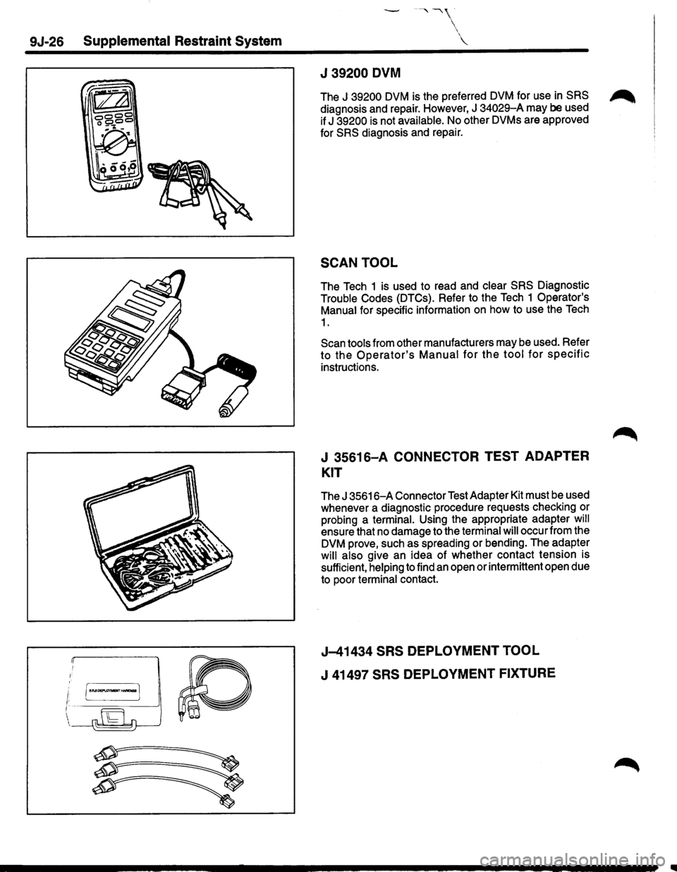
J 39200 DVM
The J 39200 DVM is the preferred DVM for use in SRS ~
diagnosis and repair. However, J 34029-A may be used
if
J 39200 is not available. No other DVMs are approved
for
SRS diagnosis and repair.
SCAN TOOL
The Tech 1 is used to read and clear SRS Diagnostic
Trouble Codes (DTCs). Refer to the Tech 1 Operator's
Manual for specific information on how to use the Tech
1.
Scan tools from other manufacturers may be used. Refer
to the Operator's Manual for the tool for specific
instructions.
J 35616-A CONNECTOR TEST ADAPTER
KIT
The J 35616-A Connector Test Adapter Kit must be used
whenever a diagnostic procedure requests checking or
probing a
terminal. Using the appropriate adapter will
ensure that no damage to the terminal will occur from the
DVM prove, such as spreading or bending. The adapter
will also give an idea of whether contact tension is
sufficient,
helping to find an open or intermittent open due
to poor
terminal contact.
J-41434 SRS DEPLOYMENT TOOL
J 41497 SRS DEPLOYMENT FIXTURE