ISUZU TROOPER 1995 Workshop Manual
Manufacturer: ISUZU, Model Year: 1995, Model line: TROOPER, Model: ISUZU TROOPER 1995Pages: 1928
Page 1611 of 1928
CRUISE CONTROL 9B-27
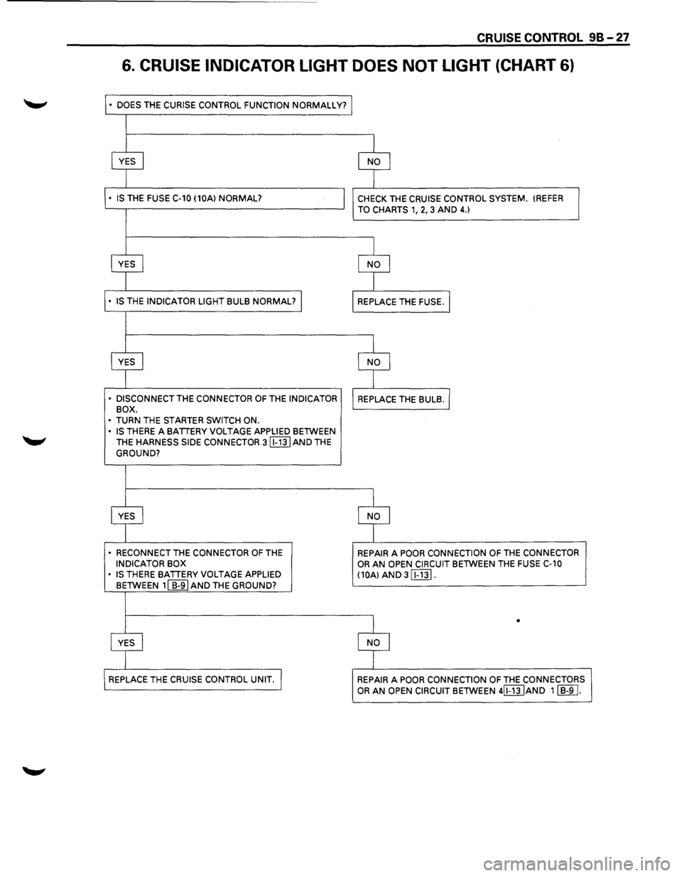
6. CRUISE INDICATOR LIGHT DOES NOT LIGHT (CHART 6)
• DOES THE CURISE CONTROL FUNCTION NORMALLY?
• DISCONNECT THE CONNECTOR OF THE INDICATOR
BOX.
•
TURN THE STARTER SWITCH ON.
• IS THERE A BATIERY VOLTAGE APPLIED BETWEEN
THE
HARNESS SIDE CONNECTOR 3 (EIT] AND THE
GROUND?
• RECONNECT THE CONNECTOR OF THE INDICATOR BOX
• IS THERE BATIERY VOLTAGE APPLIED
BETWEEN 11 B-91 AND THE GROUND?
CHECK THE CRUISE CONTROL SYSTEM. (REFER
TO CHARTS 1, 2, 3 AND 4.)
REPAIR A POOR CONNECTION OF THE CONNECTOR OR AN OPEN CIRCUIT BETWEEN THE FUSE C-10
(10A) AND 3 [Ej1].
•
REPAIR A POOR CONNECTION OF THE CONNECTORS
OR AN OPEN CIRCUIT BETWEEN 4[f"j]JAND 11 B-9 I.
Page 1612 of 1928
98-28 CRUISE CONTROL
ON-VEHICLE SERVICE
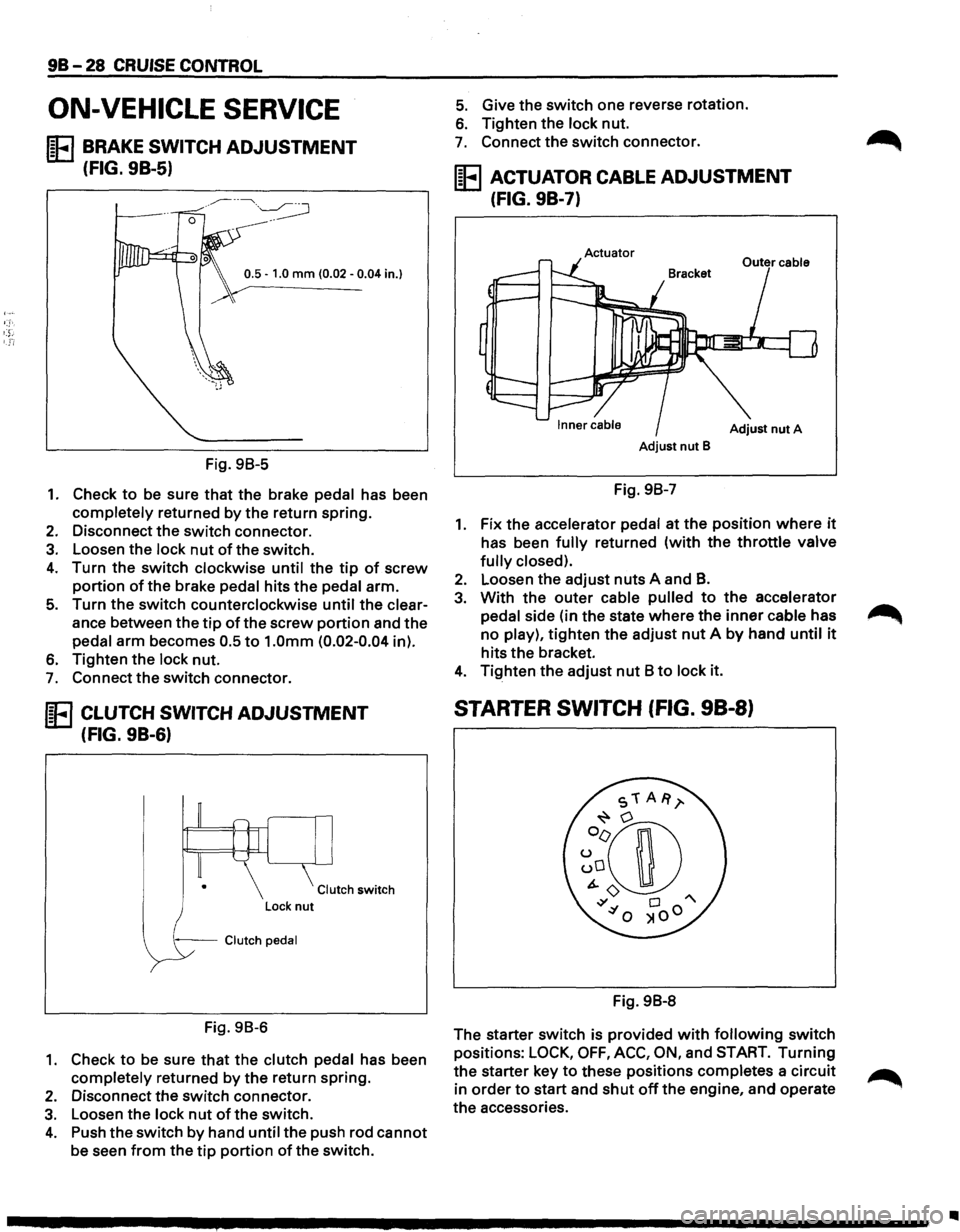
IE BRAKE SWITCH ADJUSTMENT
(FIG. 9B-5)
0.5 -1.0 mm (0.02 -0.04 in.}
Fig. 98-5
1. Check to be sure that the brake pedal has been
completely returned by the return spring.
2. Disconnect the switch connector.
3. Loosen the lock nut of the switch.
4. Turn the switch clockwise until the tip of screw
portion of the brake pedal hits the pedal arm.
5. Turn the switch counterclockwise until the clear
ance between the
tip of the screw portion and the
pedal arm becomes 0.5
to 1.0mm (0.02-0.04 in).
6. Tighten the lock nut.
7. Connect the switch connector.
IE CLUTCH SWITCH ADJUSTMENT
(FIG. 9B-6)
Clutch switch
--Clutch pedal
Fig. 98-6
1. Check to be sure that the clutch pedal has been
completely returned by
the return spring.
2. Disconnect the switch connector.
3. Loosen the lock nut of the switch.
4. Push the switch by hand until the push rod cannot
be seen from the tip portion of the switch.
5. Give the switch one reverse rotation.
6. Tighten the lock nut.
7. Connect the switch connector.
IE ACTUATOR CABLE ADJUSTMENT
(FIG. 9B-7)
Actuator
Adjust nut A
Adjust nut B
Fig. 98-7
1. Fix the accelerator pedal at the position where it
has been fully returned (with the throttle valve
fully closed).
2. Loosen the adjust nuts A and B.
3. With the outer cable pulled to the accelerator
pedal side (in the state
where the inner cable has
no play),
tighten the adjust nut A by hand until it
hits the bracket.
4. Tighten the adjust nut 8 to lock it.
STARTER SWITCH (FIG. 98-8)
Fig. 98-8
The starter switch is provided
with following switch
positions:
LOCK, OFF, ACC, ON, and START. Turning
the starter key to these positions completes a circuit
in
order to start and shut off the engine, and operate
the accessories.
Page 1613 of 1928
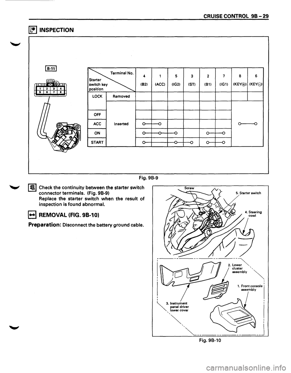
~ INSPECTION
I B-111
~
4 1
(82)
IACCI
LOCK Removed
OFF
ACC Inserted
ON -
START
Fig. 98-9
I t!l Check the continuity between the starter switch
connector
terminals. (fig. 98-9)
Replace the starter switch when the result of
inspection is found abnormal.
B REMOVAL (FIG. 98-10)
Preparation: Disconnect the battery ground cable.
5 3
IIG2) 1ST)
CRUISE CONTROL 98-29
2 7
(81) IIG1)
Fig. 98-10
8 6
IKEY(j;)) IKEY81
o----o
5. Starter switch
I
I
1. Front console I assembly
Page 1614 of 1928
9B-30 CRUISE CONTROL
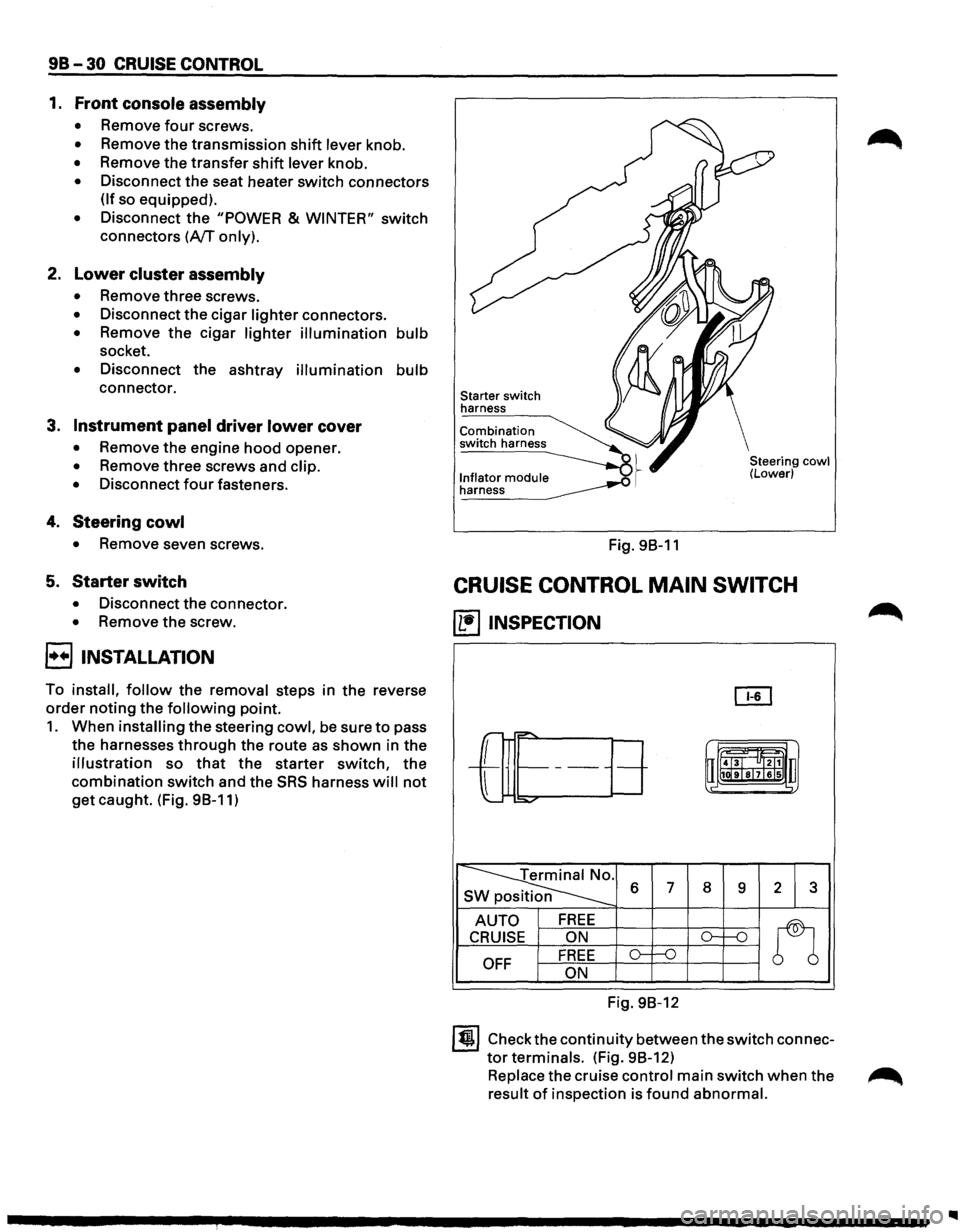
1. Front console assembly
• Remove four screws.
• Remove the transmission shift lever knob.
• Remove the transfer shift lever knob.
• Disconnect the seat heater switch connectors
(If so equipped).
• Disconnect the "POWER & WINTER" switch
connectors (A/T only).
2. Lower cluster assembly
• Remove three screws.
• Disconnect the cigar lighter connectors.
• Remove the cigar lighter illumination bulb
socket.
• Disconnect the ashtray illumination bulb
connector.
3. Instrument panel driver lower cover
• Remove the engine hood opener.
• Remove three screws and clip.
•
Disconnect four fasteners.
4. Steering cowl
• Remove seven screws.
5. Starter switch
• Disconnect the connector.
• Remove the screw.
8 INSTALLATION
To install, follow the removal steps in the reverse
order noting the following point.
1. When installing the steering cowl, be sure to pass
the harnesses
through the route as shown in the
illustration so that the starter switch, the
combination switch and the SRS harness will not
get caught. (Fig. 98-11)
Starter switch
harness
Combination
switch harness
l._n!~~~o!_ module __..o .~ ~
Fig. 98-11
Steering cowl (Lower)
CRUISE CONTROL MAIN SWITCH
(1!1 INSPECTION
OI1
r-="'
-L
r= t-------uii4J~l "ltl1 u
l
1111ilr9Tsl7lels .,
:::o.,..o-
~ s 6 7 8 9 2 3
AUTO FREE
n
CRUISE ON ()-1---n
OFF FREE o-f--0
ON
Fig. 98-12
ltjl Check the continuity between the switch connec
tor terminals. (Fig. 98-12)
Replace the cruise control main switch when the ~
result of inspection is found abnormal.
Page 1615 of 1928
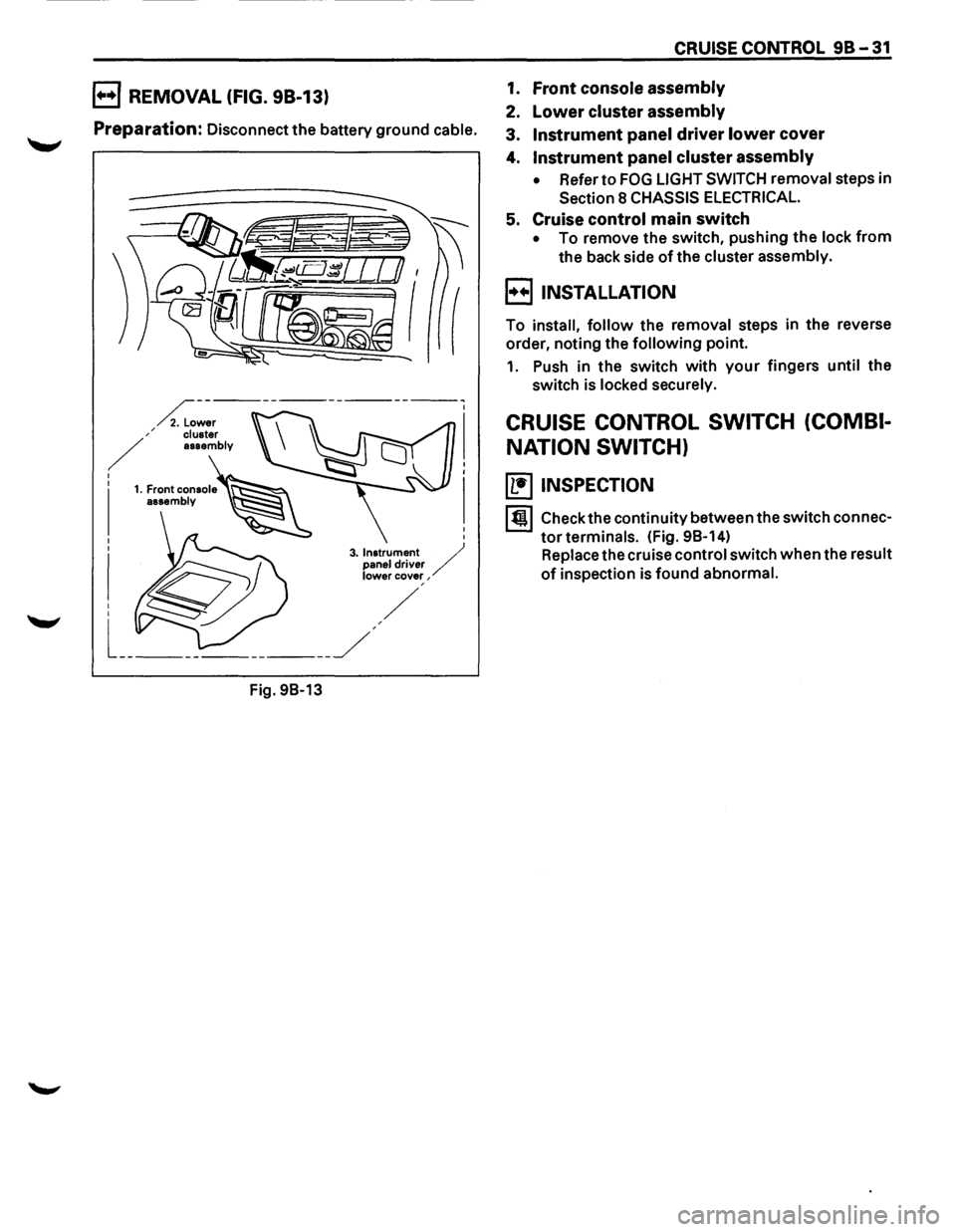
B REMOVAL (FIG. 98-13)
Preparation: Disconnect the battery ground cable.
Fig.
98-13
CRUISE CONTROL 98-31
1. Front console assembly
2. Lower cluster assembly
3. Instrument panel driver lower cover
4. Instrument panel cluster assembly
• Refer to FOG LIGHT SWITCH removal steps in
Section 8 CHASSIS ELECTRICAL.
5. Cruise control main switch
• To remove the switch, pushing the lock from
the back side of the cluster assembly.
B INSTALLATION
To install, follow the removal steps in the reverse
order, noting the
following point.
1. Push in the switch with your fingers until the
switch is locked securely.
CRUISE CONTROL SWITCH (COMBI
NATION SWITCH)
(b!] INSPECTION
I till Check the continuity between the switch connec
tor terminals. (Fig. 98-14)
Replace the cruise control switch when the result
of inspection is found abnormal.
Page 1616 of 1928
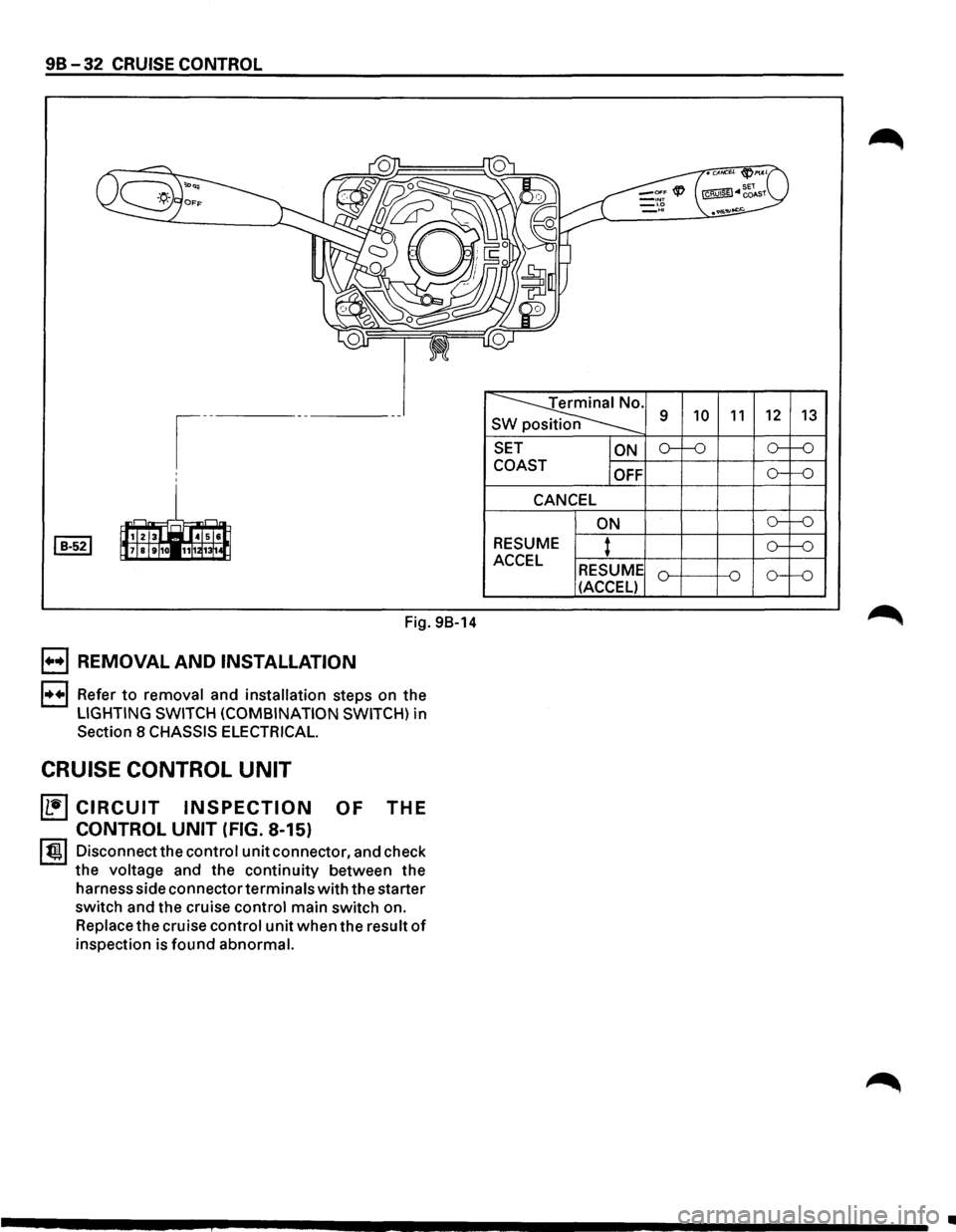
98-32 CRUISE CONTROL
Fig. 98-14
B REMOVAL AND INSTALLATION
l•+l Refer to removal and installation steps on the
LIGHTING SWITCH (COMBINATION SWITCH) in
Section 8 CHASSIS ELECTRICAL.
CRUISE CONTROL UNIT
~CIRCUIT INSPECTION OF THE
CONTROL UNIT (FIG. 8-15)
l t!ll Disconnect the control unit connector, and check
the voltage and the continuity between the
harness side connectorterminals with the starter
switch and the cruise control main switch on.
Replace the cruise control unit when the result of
inspection is found abnormal.
~-s
SET
ON
COAST
OFF
CANCEL
ON
RESUME
: ACCEL RESUME
(ACCEL) 9
10 11 12
13
o--'-0 o--f-0
o--f-0
o--'-0
o--'-0
o----o
•
Page 1617 of 1928
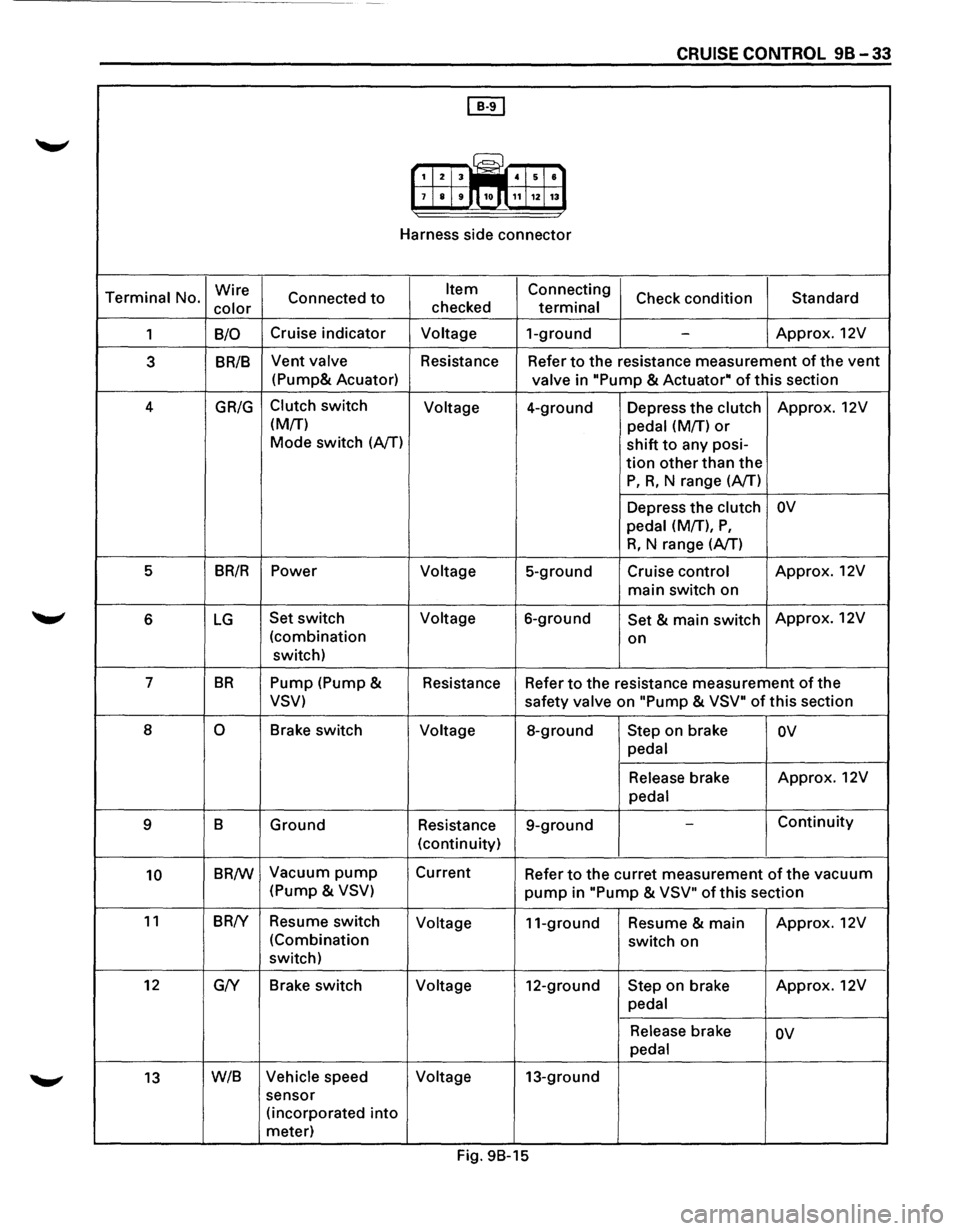
CRUISE CONTROL 98-33
[IT]
G?J 1 2 3 iiiill 4 5 8
7 8 9 10.n 11 12 13
Harness side connector
Terminal No. Wire
Connected to Item Connecting
Check condition Standard
color checked terminal
1 B/0 Cruise
indicator Voltage 1-ground -Approx. 12V
3 BR/B Vent valve
Resistance Refer to the resistance measurement of the vent
(Pump& Acuator)
valve in "Pump & Actuator• of this section
4
GR/G Clutch switch
Voltage 4-ground Depress the clutch Approx. 12V
(M/T) pedal (M/T)
or
Mode switch (AfT) shift to any posi-
tion other than the
P, R, N range (A/T)
Depress the clutch
ov
pedal (M/T), P,
R, N range (AfT)
5 BR/R Power
Voltage 5-ground Cruise control Approx.
12V
main switch on
6 LG Set switch Voltage 6-ground Set & main switch Approx.
12V
(combination on
switch)
7
BR Pump (Pump &
Resistance Refer to the resistance measurement of the
VSV) safety valve on "Pump & VSV" of this section
8
0 Brake switch Voltage 8-ground Step on brake ov
pedal
Release brake Approx.
12V
pedal
9 B Ground Resistance 9-ground
-Continuity
(continuity)
10 BR/W Vacuum pump Current
Refer to the curret measurement of the vacuum
(Pump &
VSV) pump in "Pump & VSV" of this section
11 BR!Y Resume switch
Voltage 11-ground Resume & main Approx.
12V
(Combination switch on
switch)
12 G/Y Brake
switch
Voltage 12-ground Step on brake Approx.
12V
pedal
Release brake ov
pedal
13 W/B Vehicle speed Voltage 13-ground
sensor (incorporated
into
meter)
Fig. 9B-15
Page 1618 of 1928
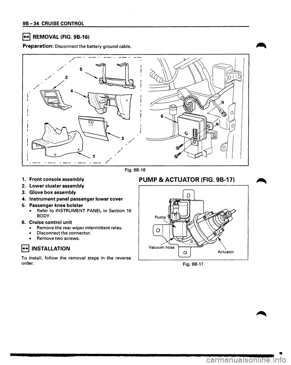
98-34 CRUISE CONTROL
B REMOVAL (FIG. 98-16)
Preparation: Disconnect the battery ground cable.
/-----/
I
J
Fig. 98-16
1. Front console assembly
2. Lower cluster assembly
3. Glove box assembly
4. Instrument panel passenger lower cover
5. Passenger knee bolster
• Refer to INSTRUMENT PANEL in Section 10
BODY.
6. Cruise control unit
• Remove the rear wiper intermittent relay.
• Disconnect the connector.
• Remove two screws.
E) INSTALLATION
To install, follow the removal steps in the reverse
order.
PUMP & ACTUATOR (FIG. 98-17)
Actuator
Fig. 98-17
..
Page 1619 of 1928
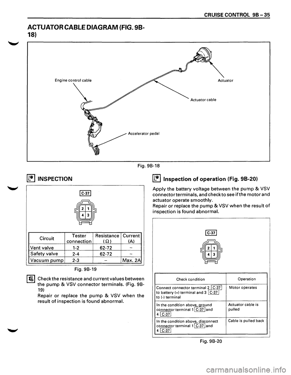
ACTUATOR CABLE DIAGRAM (FIG. 98-
18)
Engine control cable
CRUISE CONTROL 9B-35
Accelerator pedal
Fig. 98-18
~ INSPECTION
I C-371
E9
Circuit Tester
Resistance Current
connection (Q) (A)
Vent
valve 1-2 62-72 -
Safety valve 2-4 62-72 -
Vacuum pump 2-3 -Max. 2A
Fig. 98-19
I~~ Check the resistance and current values between
the
pump & VSV connector terminals. (Fig. 98-
19)
Repair or replace the pump & VSV when the
result of inspection is found abnormal.
IL1i'llnspection of operation (Fig. 98-20)
Apply the battery voltage between the pump & VSV
connector terminals, and check to see if the motor and
actuator operate
smoothly.
Repair or replace the pump & VSV when the result of
inspection is found abnormal.
I C-371
il
Check condition Operation
Connect connector
terminalll C-3~ I Motor operates
to battery(+} terminal and 3 C-37 to (-)terminal
In the condition abov~und Actuator cable is
connector
terminal 1 C-37 and pulled
41 C-371
In the condition abov
1e. disrnnect Cable is pulled back
connector
terminal 1 C-37 and
41 C-371
Fig. 98-20
Page 1620 of 1928
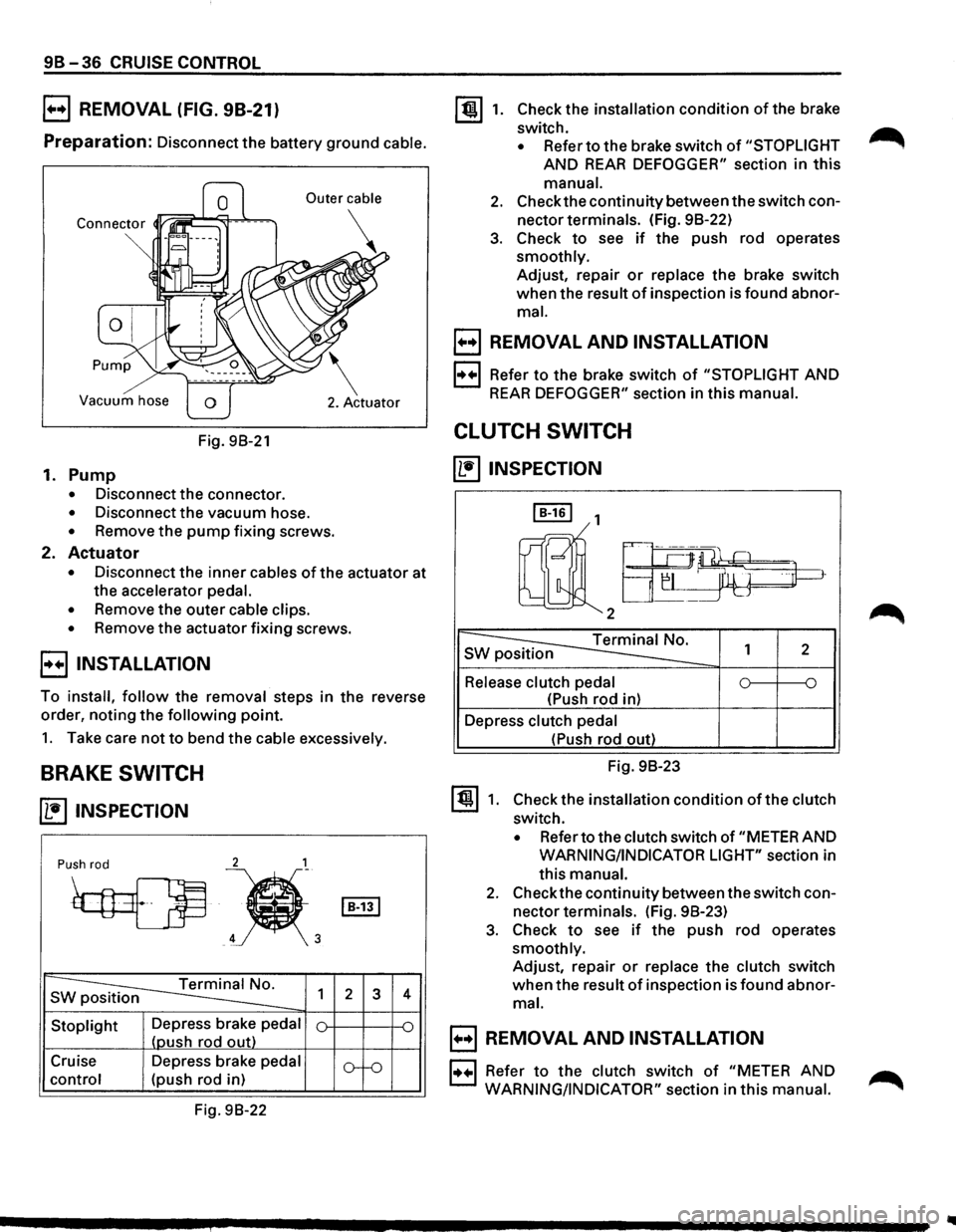
9B-36 CRUISE CONTROL
B REMOVAL (FIG. 98-21)
Preparation: Disconnect the battery ground cable.
Vacuum hose
Fig. 98-21
1. Pump
• Disconnect the connector.
• Disconnect the vacuum hose.
• Remove the pump fixing screws.
2. Actuator
• Disconnect the inner cables of the actuator at
the accelerator
pedal.
•
Remove the outer cable clips.
• Remove the actuator fixing screws.
E) INSTALLATION
To install, follow the removal steps in the reverse
order, noting
the following point.
1. Take care not to bend the cable excessively.
BRAKE SWITCH
~ INSPECTION
2 1
Push rod
~
~'
s ~ 1
Stoplight Depress brake pedal
(oush rod out)
Cruise Depress brake
pedal
control (push rod in)
Fig. 98-22
I B-131
2 3
o--o
4
~1. Check the installation condition of the brake
switch.
• Refer to the brake switch of "STOPLIGHT
AND REAR DEFOGGER" section in this
manual.
2. Check the continuity between the switch con
nector terminals. (Fig. 98-22)
3. Check to see if the push rod operates
smoothly. Adjust, repair
or replace the brake switch
when the result
of inspection is found abnor
mal.
B REMOVAL AND INSTALLATION
1·++·1 Refer to the brake switch of "STOPLIGHT AND
REAR DEFOGGER" section in this manual.
CLUTCH SWITCH
~INSPECTION
I B-161 1
rnll2a-~~
~ s 1 2
Release clutch pedal 0 ~ ~
(Push rod in)
Depress
clutch pedal
~1.
(Push rod out)
Fig. 98-23
Check the installation
condition of the clutch
switch.
• Refer to the clutch switch of "METER AND
WARNING/INDICATOR LIGHT" section in
this
manual.
2. Check the continuity between the switch con
nector terminals. (Fig. 98-23)
3. Check to see if the push rod operates
smoothly. Adjust, repair
or replace the clutch switch
when the result of inspection is found abnor
mal.
B REMOVAL AND INSTALLATION
1••1 Refer to the clutch switch of "METER AND ...-...
WARNING/INDICATOR"
section in this manual. ,...........