ISUZU TROOPER 1995 Workshop Manual
Manufacturer: ISUZU, Model Year: 1995, Model line: TROOPER, Model: ISUZU TROOPER 1995Pages: 1928
Page 1881 of 1928
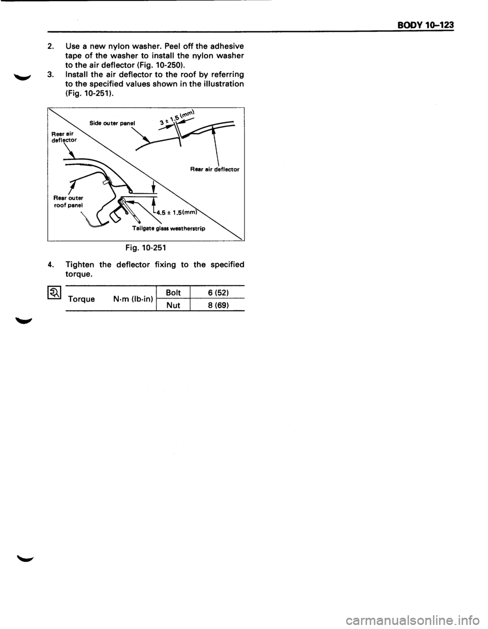
2. Use a new nylon washer. Peel off the adhesive
tape
of the washer to install the nylon washer
to the air deflector (Fig. 10-250).
3. Install the air deflector to the roof by referring
to the specified values shown in the illustration
(Fig. 10-251).
Rear air deflector
Fig. 10-251
4. Tighten the deflector fixing to the specified
torque.
~~~ Torque Bolt 6
(52) N·m (lb·in) 1----t-----'-------'-----Nut 8 (69)
BODY 10-123
Page 1882 of 1928
10-124 BODY
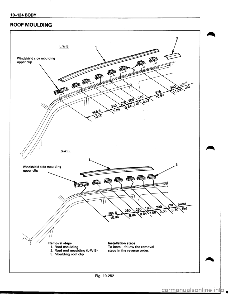
ROOF MOULDING
Windshield side moulding
upper clip
L.W·B
S.W·B
Windshield side moulding
upper clip
Removal steps 1. Roof moulding Installation steps
2. Roof end moulding (L·W·B) To install, follow the removal steps in the reverse order. 3. Moulding roof clip
Fig. 10-252
•
Page 1883 of 1928
1••1 REMOVAL
Preparation: Battery ground cable
1. Roof moulding
2. Roof end moulding (L·W·B)
• Remove the sealing adhesive and adhesive
tape
of the moulding from the body panel
with a knife or scraper while peeling them
off.
3. Moulding roof clip
• Peel the adhesive tape and remove it.
I••! INSTALLATION
3. Moulding roof clip
• Clean the body panel to which the clip is
attached.
• Install the clips with adhesive tape (Fig. 10-
252, 253).
Roof panel flange
Roof panel
Adhesive tape
Fig. 10-253
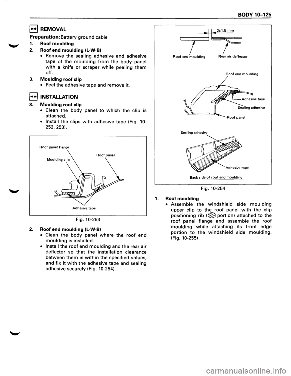
2. Roof end moulding (l·W·B)
• Clean the body panel where the roof end
moulding is installed.
• Install
the roof end moulding and the rear air
deflector so that the installation clearance
between them is within the specified values,
and fix it with the adhesive tape and sealing
adhesive securely (Fig. 10-254).
BODY 10-125
t------.,.-lll•3±1.5 mm
7 I Roof end moulding Rear air deflector
Roof end moulding
Sealing adhesive
Adhesive
tape
Back side of roof end moulding
Fig. 10-254
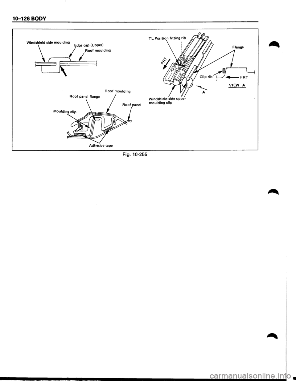
1. Roof moulding
• Assemble the windshield side moulding
upper clip to the roof panel with the clip
positioning rib (~portion) attached to the
roof panel flange and assemble the roof
moulding while attaching its front edge
portion to the windshield side moulding.
(Fig. 10-255)
Page 1884 of 1928
10-126 BODY
Windshield side moulding Edge cap (Upper)
Roof moulding
Roof moulding
Moulding clip
Adhesive tape
Fig. 10-255
TL Position fitting rib
VIEW A
•
Page 1885 of 1928
BODY 10-127
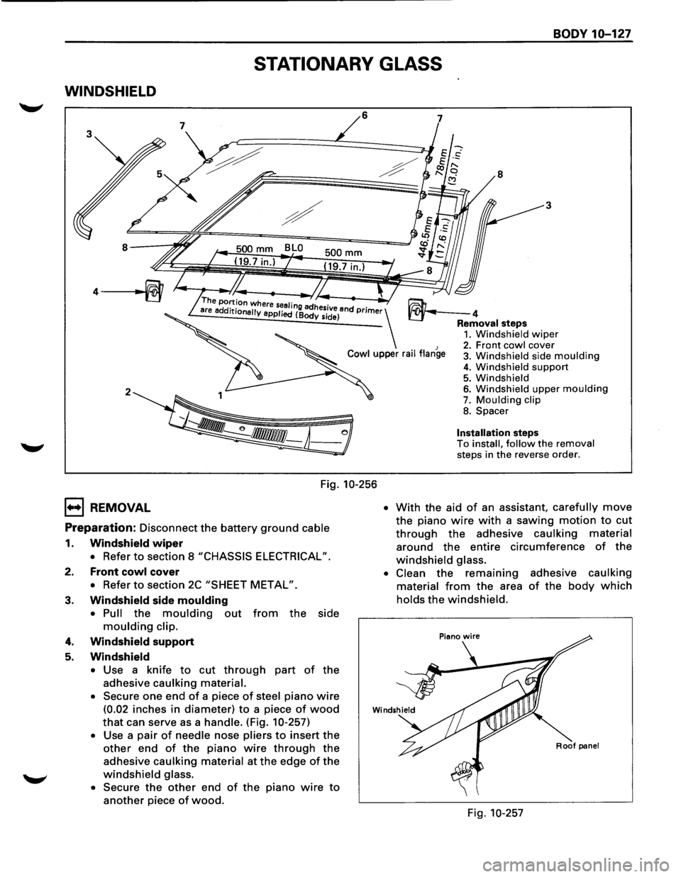
STATIONARY GLASS
WINDSHIELD
6
2
Fig. 10-256
1••1 REMOVAL
Preparation: Disconnect the battery ground cable
1. Windshield wiper
• Refer to section 8 "CHASSIS ELECTRICAL".
2. Front cowl cover
• Refer to section 2C "SHEET METAL".
3. Windshield side moulding
• Pull the moulding out from the side
moulding clip.
4. Windshield support
5. Windshield
• Use a knife to cut through part of the
adhesive caulking material.
•
Secure one end of a piece of steel piano wire
(0.02 inches in diameter) to a piece of wood
that can serve as a handle. (Fig. 10-257)
• Use a pair of needle nose pliers to insert the
other end of the piano wire through the
adhesive caulking material at the edge of the
windshield glass.
•
Secure the other end of the piano wire to
another piece of wood.
7
8
3
~4 Removal steps 1. Windshield wiper 2. Front cowl cover 3. Windshield side moulding
4. Windshield support 5. Windshield 6. Windshield upper moulding 7. Moulding clip
8. Spacer
Installation steps To install, follow the removal steps in the reverse order.
• With the aid of an assistant, carefully move
the piano wire with a sawing motion to cut
through the adhesive caulking material
around the entire circumference of the
windshield glass.
• Clean
the remaining adhesive caulking
material
from the area of the body which
holds the windshield.
Roof panel
Fig. 10-257
Page 1886 of 1928
10-128 BODY
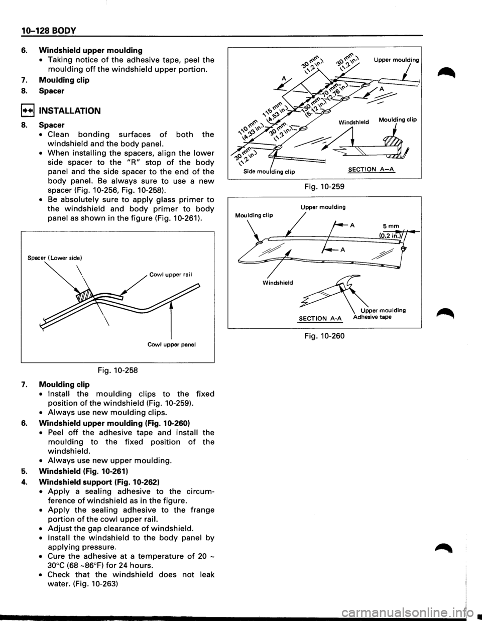
6. Windshield upper moulding
• Taking notice of the adhesive tape, peel the
moulding off the windshield upper portion.
7. Moulding clip
8. Spacer
I••! INSTALLATION
8. Spacer
• Clean bonding surfaces of both the
windshield and the body panel.
•
When installing the spacers, align the lower
side spacer to the "R" stop of the body
panel and the side spacer to the end of the
body panel. Be always sure to use a new
spacer (Fig. 10-256, Fig. 1 0-258).
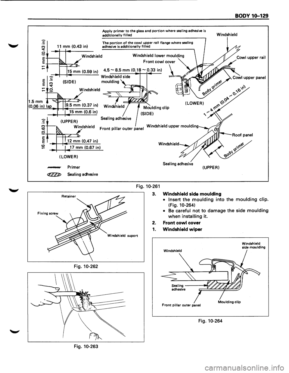
• Be absolutely sure to apply glass primer to
the windshield and body primer to body
panel as shown in the figure (Fig. 10-261).
Spacer (Lower side)
Cowl upper rail
Cowl
upper panel
Fig. 10-258
7. Moulding clip
• Install the moulding clips to the fixed
position of the windshield (Fig. 10-259).
• Always use new moulding clips.
6. Windshield upper moulding (Fig. 10-260)
• Peel off the adhesive tape and install the
moulding to the fixed position of the
windshield.
• Always use new upper moulding.
5. Windshield (Fig. 10-261)
4. Windshield support (Fig. 10-262)
• Apply a sealing adhesive to the circum
ference of windshield as in the figure.
• Apply the sealing adhesive to the frange
portion of the cowl upper rail.
•
Adjust the gap clearance of windshield.
• Install the windshield to the body panel by
applying pressure.
• Cure the adhesive at a temperature of 20 -
30°C
(68 -86°F) for 24 hours.
• Check that the windshield does not leak
water. (Fig. 10-263)
Upper moulding
Moulding clip
Side moulding clip SECTION A-A
Fig. 10-259
Upper moulding
Moulding clip
A
Windshield
Upper moulding SECTION A-A Adhesive tape
Fig. 10-260
•
Page 1887 of 1928
...... ......
1.5mm
(0.06 in) Ia
11 mm (0.43 in)
15 mm (0.6 in)
(UPPER)
Apply primer to the glass and portion where sealing adhesive is additionally filled
The portion of the cowl upper rail flange where sealing
adhesive is additionally filled
(LOWER)
Windshield upper moulding Front pillar outer panel
Windshield
BODY 1Q-129
Windshield
17 mm (0.67 in)
(LOWER)
.-IHHW Primer
Fig. 10-263
Fig. 10-261
3.
2.
1.
Sealing adhesive (UPPER)
Windshield side moulding
• Insert the moulding into the moulding clip.
(Fig.
10-264)
• Be careful not to damage the side moulding
when installing it.
Front cowl cover
Windshield wiper
Front pillar outer panel
Fig. 10-264
Windshield
side moulding
Page 1888 of 1928
10-130 BODY
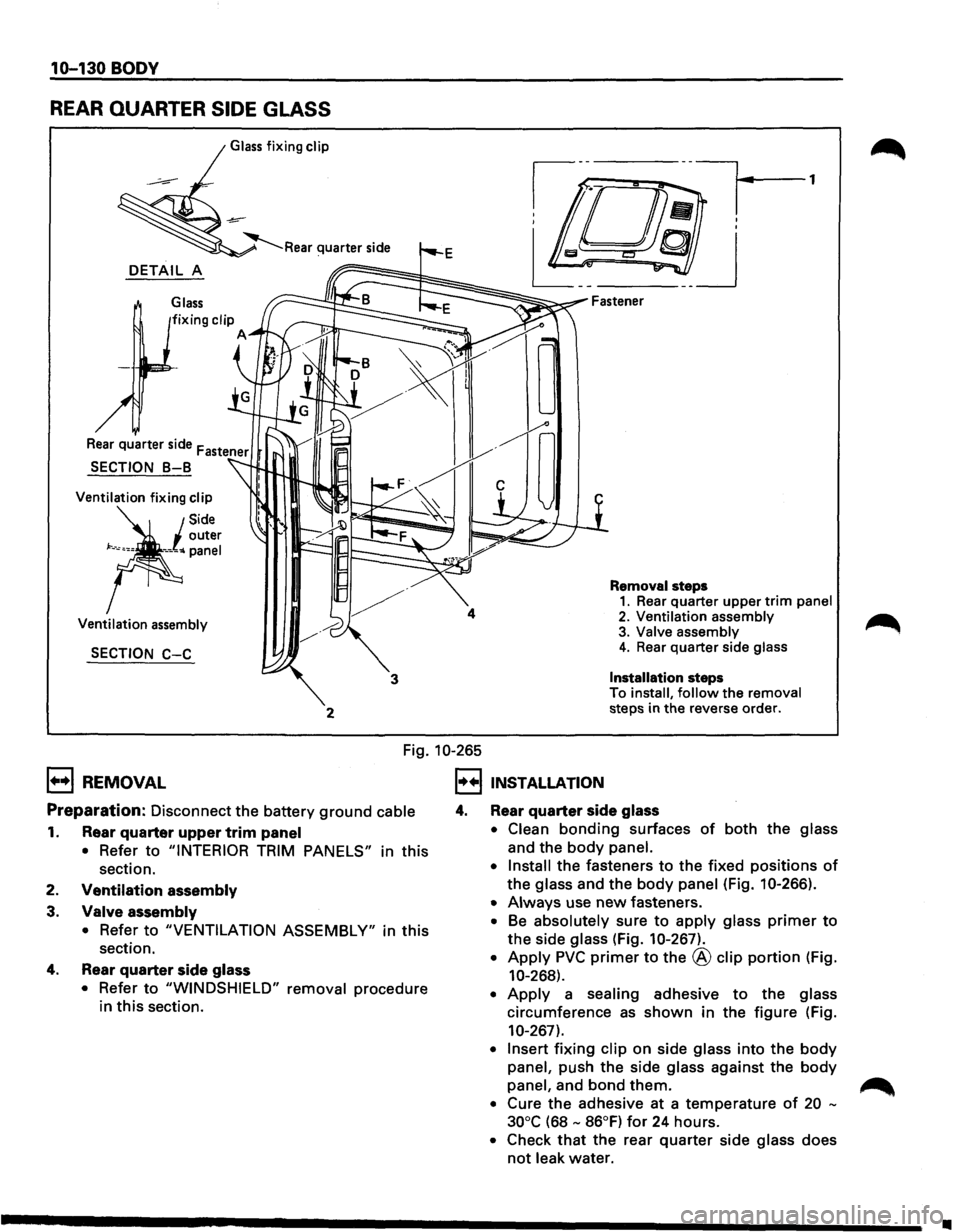
REAR QUARTER SIDE GLASS
Glass fixing clip
DETAIL A
Glass
Ventilation fixing clip
Ventilation assembly
SECTION C-C
2
4
3
Removal steps 1. Rear quarter upper trim panel
2. Ventilation assembly 3. Valve assembly 4. Rear quarter side glass
Installation
steps
To install, follow the removal steps in the reverse order.
Fig. 10-265
1+•1 REMOVAL
Preparation: Disconnect the battery ground cable
1. Rear quarter upper trim panel
• Refer to "INTERIOR TRIM PANELS" in this
section.
2.
Ventilation assembly
3.
Valve assembly
• Refer to "VENTILATION ASSEMBLY" in this
section.
4. Rear quarter side glass
• Refer to "WINDSHIELD" removal procedure
in this section.
I•+! INSTALLATION
4. Rear quarter side glass
• Clean bonding surfaces of both the glass
and the
body panel.
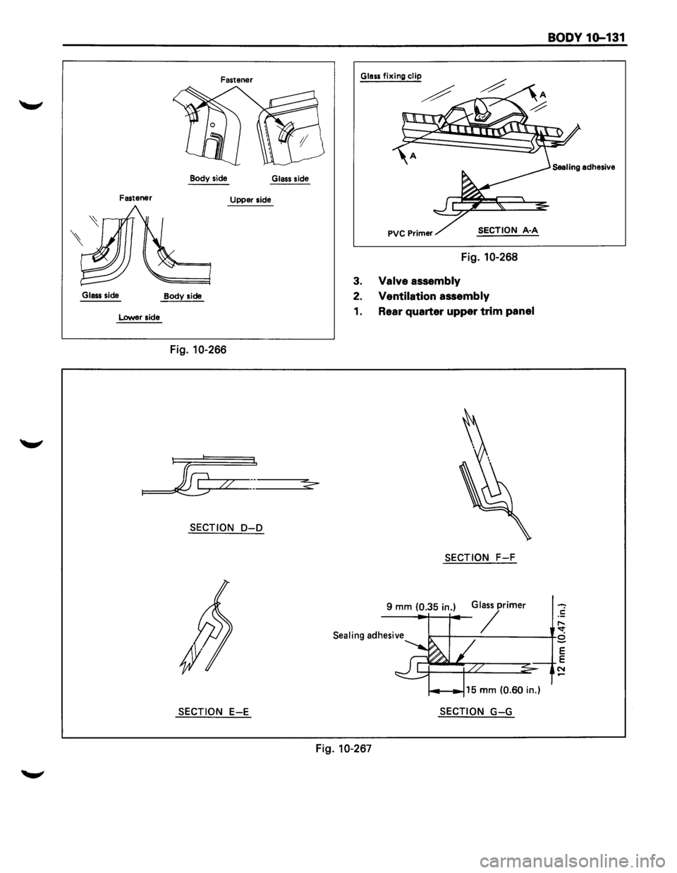
• Install
the fasteners to the fixed positions of
the glass and the body panel (Fig. 10-266).
• Always use new fasteners.
• Be absolutely sure to apply glass primer to
the side glass (Fig. 10-267).
• Apply PVC primer to the @ clip portion (Fig.
10-268).
• Apply a sealing adhesive to the glass
circumference
as shown in the figure (Fig.
10-267).
• Insert fixing clip on side glass into the body
panel, push the side glass against the body
panel, and bond them. ~
• Cure the adhesive at a temperature of 20 -
30°C
(68 - 86°F) for 24 hours.
• Check that the rear quarter side glass does
not leak water.
•
Page 1889 of 1928
Fastener
Body side
Glass side
Fastener Upper side
Glass side
Body side
Lower side
Fig. 10-266
SECTION D-D
SECTION E-E
BODY 1G-131
Glass fixing clip
SECTION A·A
Fig. 10-268
3. Valve assembly
2. Ventilation assembly
1. Rear quarter upper trim panel
SECTION F-F
Glass primer
/ ~ ~-+--~-----------+s
9 mm (0.35 in.)
Sealing adhesive
SECTION G-G
Fig. 10-267
E
E
N
Page 1890 of 1928
10-132 BODY
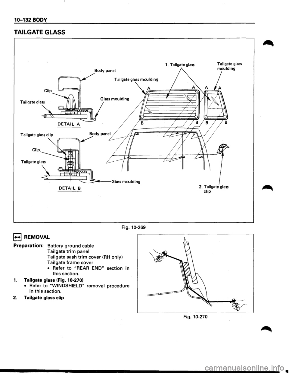
TAILGATE GLASS
Clip
~Body P"'el
Tailgate glass
DETAIL A
Body pen£ Tailgate glass clip
Clip
Tailgate glass
DETAIL B
1••1 REMOVAL
Preparation: Battery ground cable
Tailgate
trim panel Fig.
10-269
Tailgate sash
trim cover (RH only)
Tailgate
frame cover
• Refer to "REAR END" section in
this section.
1. Tailgate glass (Fig. 10-270)
• Refer to "WINDSHIELD" removal procedure
in
this section.
2. Tailgate glass clip
1. Tailgate glass
2. Tailgate glass
clip
Fig. 10-270
Ill