ISUZU TROOPER 1995 Workshop Manual
Manufacturer: ISUZU, Model Year: 1995, Model line: TROOPER, Model: ISUZU TROOPER 1995Pages: 1928
Page 1861 of 1928
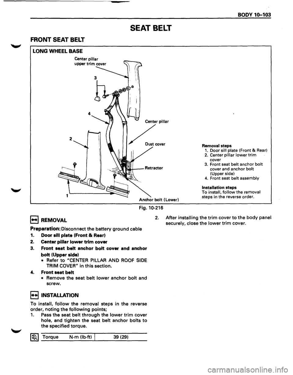
FRONT SEAT BELT
LONG WHEEL BASE
2
1
Center pillar
upper trim cover
SEAT BELT
Center pillar
~ .....
Anchor bolt (Lower)
Fig. 10-216
BODY 1Q-103
Removal steps 1. Door sill plate (Front & Rear)
2. Center pillar lower trim cover 3. Front seat belt anchor bolt cover and anchor bolt (Upper side) 4. Front seat belt assembly
Installation
steps
To install, follow the removal
steps in the reverse order.
B REMOVAL 2. After installing the trim cover to the body panel
securely, close
the lower trim cover.
Preparation: Disconnect the battery ground cable
1. Door sill plate (Front & Rear)
2. Center pillar lower trim cover
3. Front seat belt anchor bolt cover and anchor
bolt (Upper side)
• Refer to "CENTER PILLAR AND ROOF SIDE
TRIM COVER" in this section.
4. Front seat belt
• Remove the seat belt lower anchor bolt and
screw.
I••IINSTALLATION
To install, follow the removal steps in the reverse
order, noting the
following points;
1. Pass the seat belt through the lower trim cover
hole, and tighten the seat belt anchor bolts to
the specified torque.
~~~ Torque N·m (lb·ft) I 39 (29)
Page 1862 of 1928
----
10-104 BODY
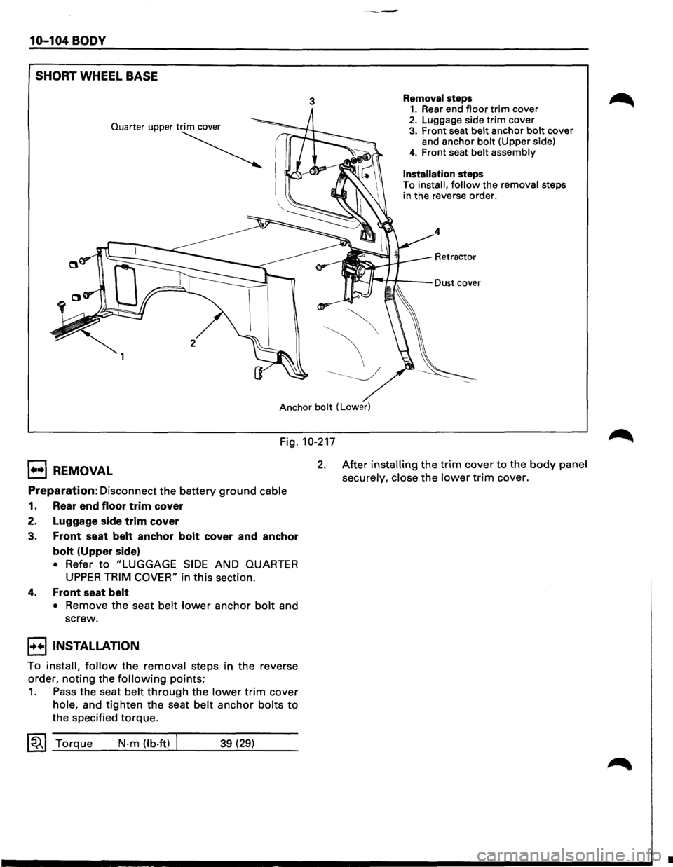
SHORT
WHEEL BASE
3 Removal steps 1. Rear end floor trim cover 2. Luggage side trim cover 3. Front seat belt anchor bolt cover
and anchor bolt (Upper side)
4. Front seat belt assembly
Installation steps
To install, follow the removal steps
in the reverse order.
4
Retractor
Anchor bolt (Lower)
Fig. 10-217
1++1 REMOVAL
Preparation: Disconnect the battery ground cable
1. Rear end floor trim cover
2. Luggage side
trim cover
3.
Front seat belt anchor bolt cover and anchor
bolt (Upper side)
• Refer to "LUGGAGE SIDE AND QUARTER
UPPER TRIM COVER" in this section.
4. Front seat belt
• Remove the seat belt lower anchor bolt and
screw.
I••IINSTALLATION
To install, follow the removal steps in the reverse
order,
noting the following points;
1. Pass the seat belt through the lower trim cover
hole, and tighten the seat belt anchor bolts to
the specified torque.
~~~ Torque N-m (lb·ft) 39 (29)
2. After installing the trim cover to the body panel
securely, close
the lower trim cover.
•
Page 1863 of 1928
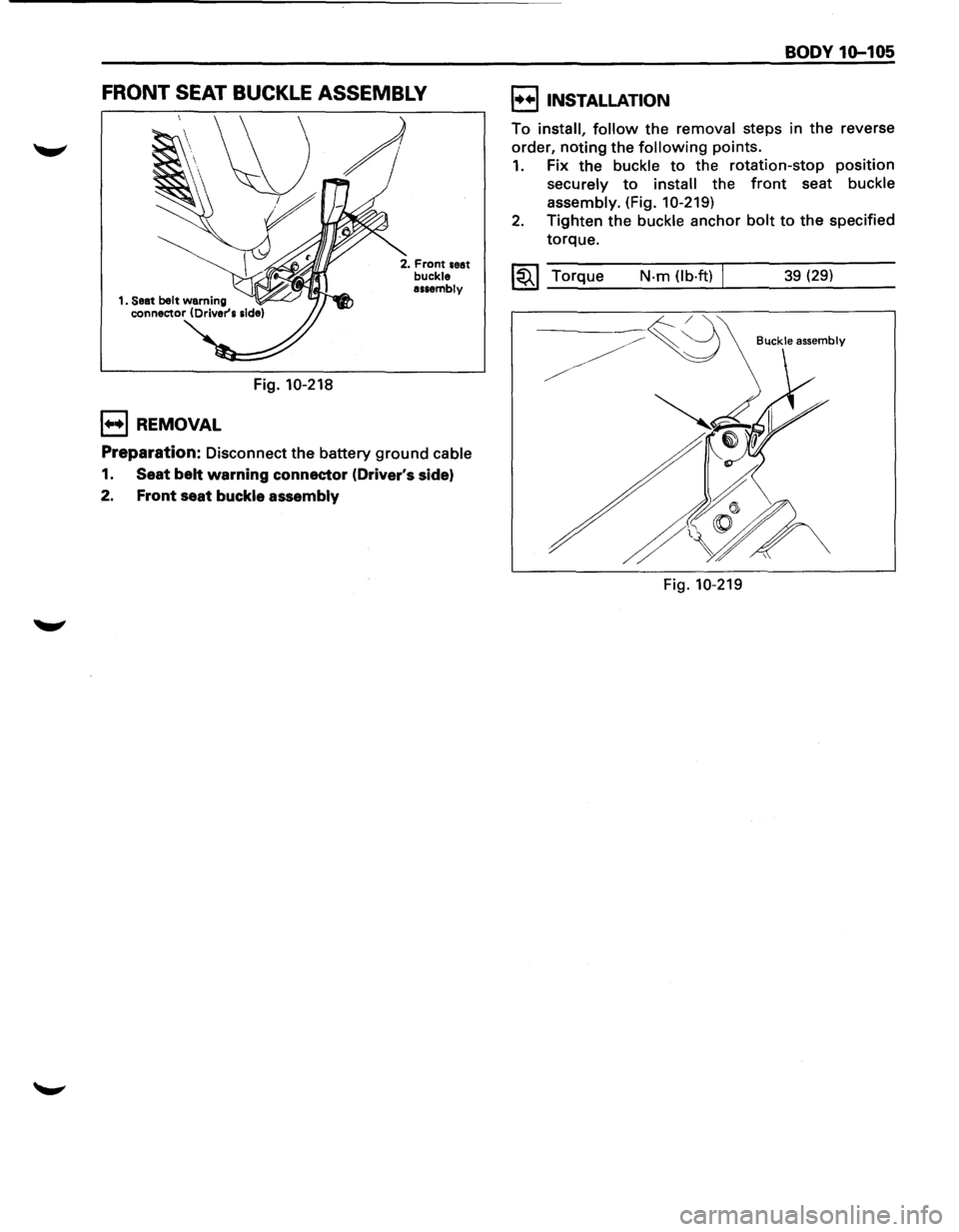
FRONT SEAT BUCKLE ASSEMBLY
Fig. 10-218
1++1 REMOVAL
2. Front seat buckle assembly
Preparation: Disconnect the battery ground cable
1. Seat belt warning connector (Driver's side)
2. Front seat buckle assembly
BODY 1Q-105
I••IINSTALLATION
To install, follow the removal steps in the reverse
order, noting the following points.
1. Fix the buckle to the rotation-stop position
securely to install the front seat buckle
assembly.
(Fig. 10-219)
2. Tighten the buckle anchor bolt to the specified
torque.
~~~ Torque N·m (lb·ft) I 39 (29)
Buckle assembly
Fig. 10-219
Page 1864 of 1928
10-106 BODY
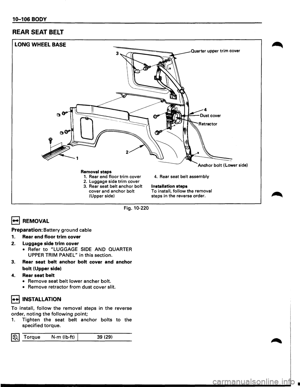
REAR SEAT BELT
LONG WHEEL BASE
B REMOVAL
Removal steps 1. Rear end floor trim cover 2. Luggage side trim cover
3. Rear seat belt anchor bolt cover and anchor bolt (Upper side)
Fig. 10-220
Preparation: Battery ground cable
1. Rear end floor trim cover
2. Luggage side
trim cover
• Refer to "LUGGAGE SIDE AND QUARTER
UPPER TRIM PANEL" in this section.
3. Rear seat belt anchor bolt cover and anchor
bolt (Upper side)
4. Rear seat belt
• Remove seat belt lower ancher bolt.
•
Remove retractor from dust cover slit.
I••IINSTALLATION
To install, follow the removal steps in the reverse
order,
noting the following point;
1. Tighten the seat belt anchor bolts to the
specified torque.
~~~ Torque N·m (lb.ft) 39 (29)
Quarter upper trim cover
4. Rear seat belt assembly
Installation steps
To install, follow the removal steps in the reverse order.
•
Page 1865 of 1928
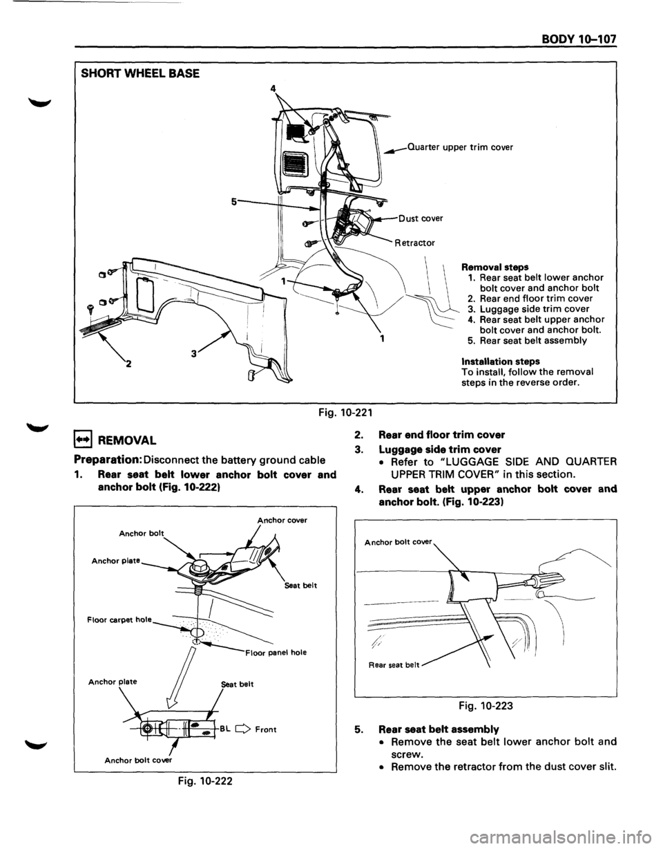
SHORT WHEEL BASE
4
1
BODY 1o-101
Installation steps
To install, follow the removal
steps in the reverse order.
Fig. 10-221
1+•1 REMOVAL
Preparation: Disconnect the battery ground cable
1. Rear seat belt lower anchor bolt cover and
anchor bolt (Fig. 10-222)
Anchor cover
Anchor plate
Anchor plate
Anchor bolt cover
Fig. 10-222
2. Rear end floor trim cover
3. Luggage side trim cover
• Refer to "LUGGAGE SIDE AND QUARTER
UPPER TRIM COVER" in this section.
4. Rear seat belt upper anchor bolt cover and
anchor bolt. (fig. 10-223)
5.
A ear seat be It
Fig. 10-223
Rear seat belt assembly
•
Remove the seat belt lower anchor bolt and
screw.
• Remove the retractor from the dust cover slit.
Page 1866 of 1928
10-108 BODY
!••I INSTALLATION
To install, follow the removal steps in the reverse
order,
noting the following points.
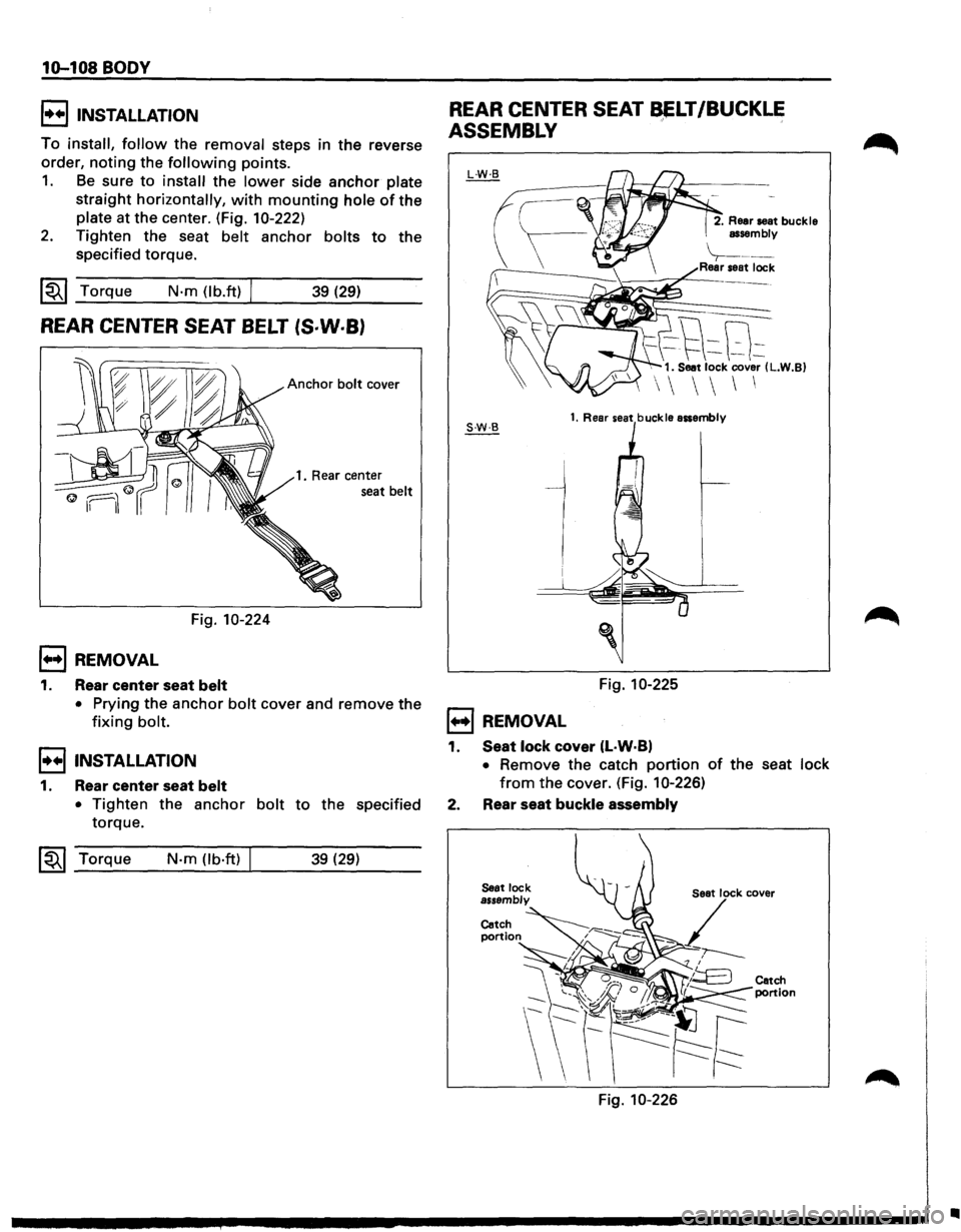
1. Be sure to install the lower side anchor plate
straight horizontally, with mounting hole of the
plate at the center. (Fig. 10-222)
2. Tighten the seat belt anchor bolts to the
specified torque.
~~~ Torque N·m (lb.ft) / 39 (29)
REAR CENTER SEAT BELT (S·W·B)
Anchor bolt cover
1. Rear center
seat
belt
Fig. 10-224
1••1 REMOVAL
1. Rear center seat belt
• Prying the anchor bolt cover and remove the
fixing bolt.
I••IINSTALLATION
1. Rear center seat belt
• Tighten the anchor bolt to the specified
torque.
~~~ Torque N-m (lb·ft) 39 (29)
REAR CENTER SEAT ~LT/BUCKLE
ASSEMBLY
1••1 REMOVAL
2. Rear seat buckle
assembly
\----Rear seat lock
--t\8~ 1. Seat lock cover (L.W.B)
1. Rear seat buckle assembly
Fig. 10-225
1. Seat lock cover (L·W·B)
• Remove the catch portion of the seat lock
from the cover. (Fig. 10-226)
2. Rear seat buckle assembly
Catch
portion
Fig. 10-226
Catch
portion
•
Page 1867 of 1928
BODY 1G-109
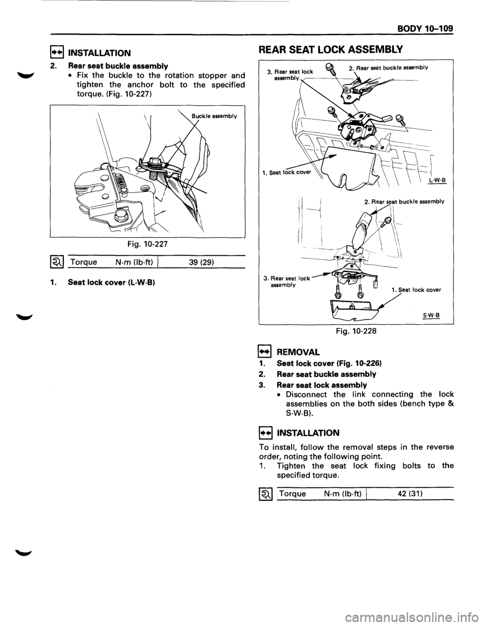
E) INSTALLATION REAR SEAT LOCK ASSEMBLY
2. Rear seat buckle assembly
"-"' • Fix the buckle to the rotation stopper and
tighten the anchor bolt to the specified
torque. (Fig. 10-227)
Fig. 10-227
1~1 Torque N-m (lb-ft) I 39 (29)
1. Seat lock cover (l·W·B)
I --j I
3. Rear seat lock ---~~ai~~'"ll assembly
' 1. Seat lock cover
~
Fig. 10-228
1••1 REMOVAL
1. Seat lock cover (Fig. 10-226)
2. Rear seat
buckle assembly
3. Rear seat lock assembly
• Disconnect the link connecting the lock
assemblies
on the both sides (bench type &
S-W·B).
I••! INSTALLATION
To install, follow the removal steps in the reverse
order,
noting the following point.
1. Tighten the seat lock fixing bolts to the
specified
torque.
~~~ Torque N·m (lb·ft) 42 (31)
Page 1868 of 1928
10-110 BODY
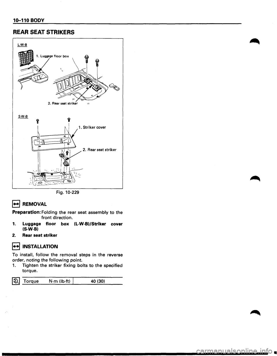
REAR SEAT STRIKERS
2. Rear seat striker ,_,_.
1. Striker cover
Fig. 10-229
1••1 REMOVAL
Preparation: Folding the rear seat assembly to the
front direction.
1. Luggage floor box (L·W·B)/Striker cover
(S·W·B)
2. Rear seat striker
I••IINSTALLATION
To install, follow the removal steps in the reverse
order,
noting the following point.
1. Tighten the striker fixing bolts to the specified
torque.
~~~ Torque N-m (lb.ft) J 40 (30)
•
Page 1869 of 1928
BODY 10-111
ROOF
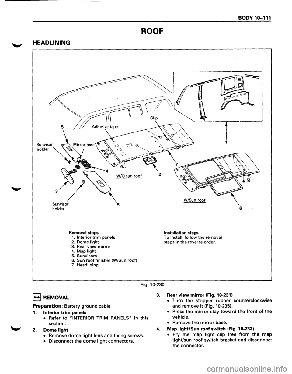
HEADLINING
~---~~I
~r CUp ''-. _ __j
5 1 Adh.,;,;, tap• . T
1
W /0 sun roof 2
Sunvisor
holder 5
Removal steps 1. Interior trim panels 2. Dome light 3. Rear view mirror 4. Map light 5. Sunvisors 6. Sun roof finisher (W/Sun roof) 7. Headlining W/Sun
roof
Installation steps To install, follow the removal steps
in the reverse order. 6
Fig. 10-230
1••1 REMOVAL
Preparation: Battery ground cable
1. Interior trim panels
•
Refer to "INTERIOR TRIM PANELS" in this
section.
2. Dome light
• Remove dome light lens and fixing screws.
• Disconnect the dome light connectors.
3. Rear view mirror (Fig. 10-231)
• Turn the stopper rubber counterclockwise
and remove
it (Fig. 10-235).
• Press the mirror stay toward the front of the
vehicle.
•
Remove the mirror base.
4. Map light/Sun roof switch (Fig. 10-232)
• Pry the map light clip free from the map
light/sun roof switch bracket and disconnect
the connector.
Page 1870 of 1928
10-112 BODY
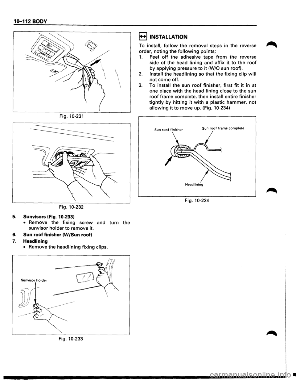
Fig. 10-231
Fig. 10-232
5. Sunvisors (fig. 10·233)
•
Remove the fixing screw and turn the
sunvisor holder to remove it.
6.
Sun roof finisher (W /Sun roof)
7.
Headlining •
Remove the headlining fixing clips.
Sunvisor holder
J
~l I I : 1/
&
Fig. 10-233
I••IINSTALLATION
To install, follow the removal steps in the reverse
order,
noting the following points;
1. Peel off the adhesive tape from the reverse
side
of the head lining and affix it to the roof
by applying pressure to it (W/0 sun roof).
2. Install the headlining so that the fixing clip will
not come off.
3. To install the sun roof finisher, first fit it in at
one
place with the head lining close to the sun
roof frame complete, then install entire finisher
tightly by hitting it with a plastic hammer, not
allowing it to move up. (Fig. 10-234)
Sun roof finisher Sun roof frame complete
Headlining
Fig. 10-234
•