ISUZU TROOPER 1995 Workshop Manual
Manufacturer: ISUZU, Model Year: 1995, Model line: TROOPER, Model: ISUZU TROOPER 1995Pages: 1928
Page 1871 of 1928
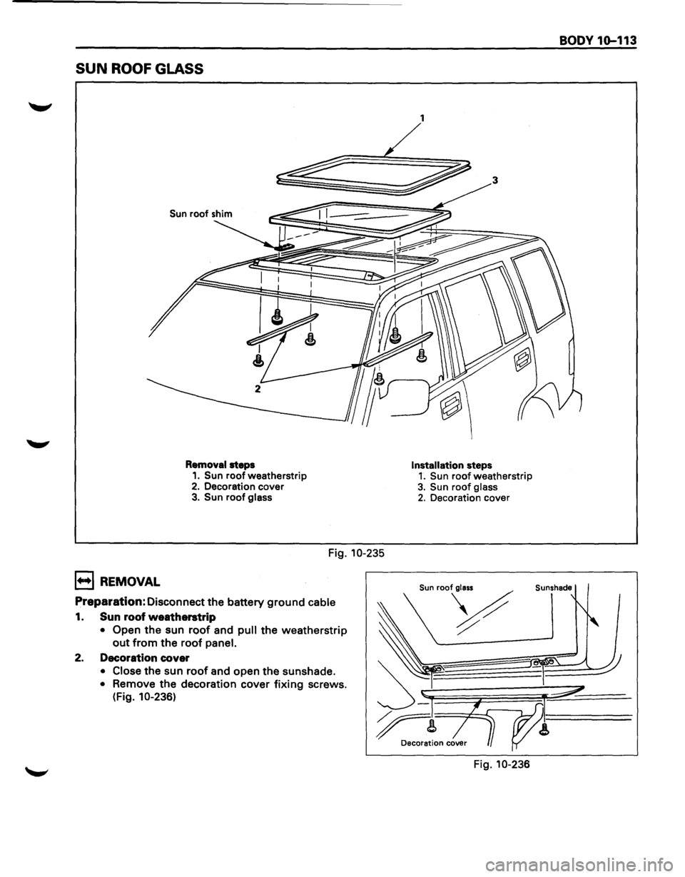
SUN ROOF GLASS
Sun roof shim
Removal steps 1. Sun roof weatherstrip 2. Decoration cover 3. Sun roof glass
Fig. 10-235
B REMOVAL
Preparation: Disconnect the battery ground cable
1. Sun roof weatherstrip
• Open the sun roof and pull the weatherstrip
out from the roof panel.
2. Decoration cover
• Close the sun roof and open the sunshade.
• Remove the decoration cover fixing screws.
(Fig. 10-236)
1
Installation steps 1. Sun roof weatherstrip
3. Sun roof glass 2. Decoration cover
Fig. 10-236
BODY 1Q-113
Page 1872 of 1928
10-114 BODY
3. Sun roof glass
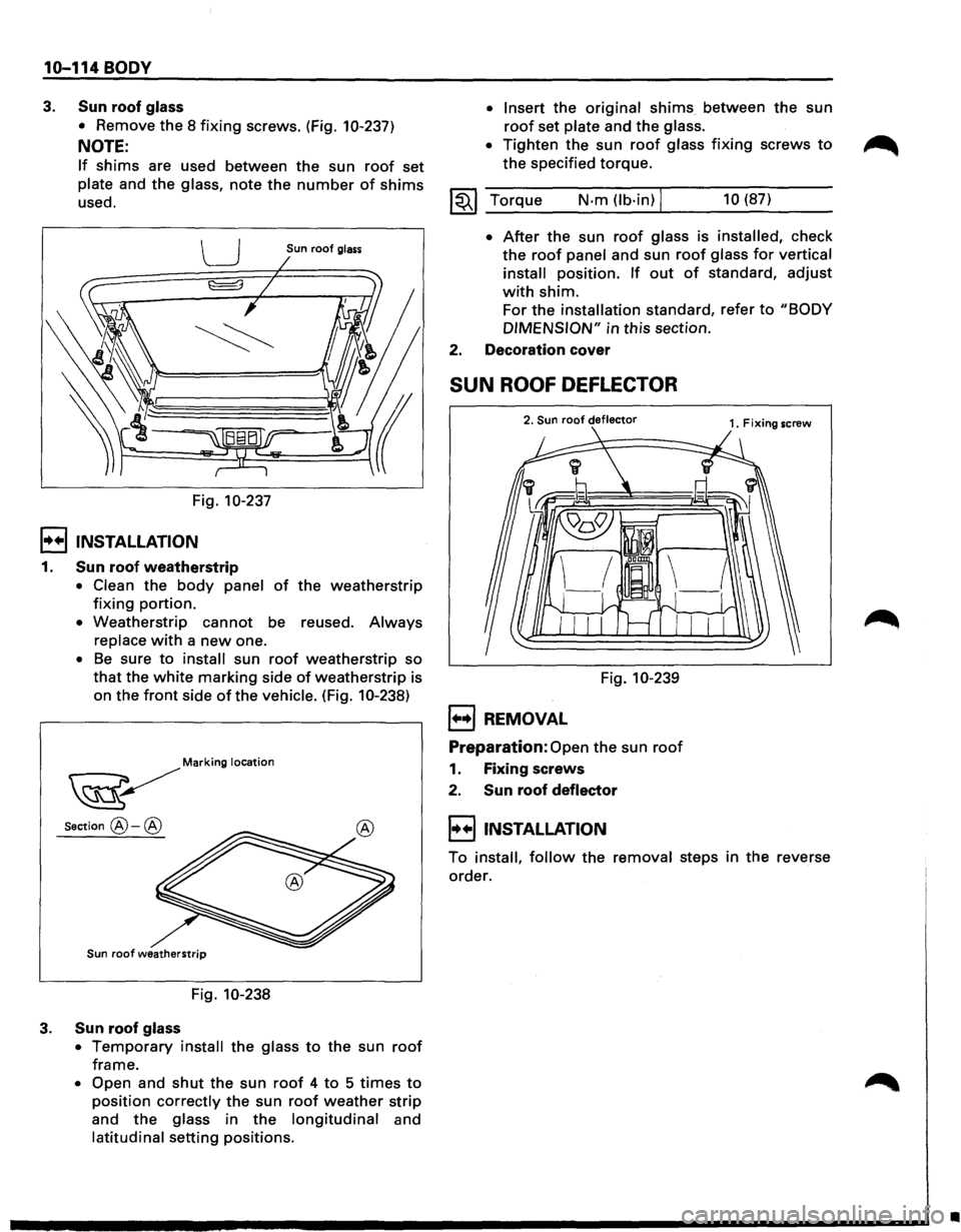
• Remove the 8 fixing screws. (Fig. 10-237)
NOTE:
If shims are used between the sun roof set
plate and the glass, note the number of shims
used.
u Sun roof glass
Fig. 10-237
l·u·IINSTALLATION
1. Sun roof weatherstrip
• Clean the body panel of the weatherstrip
fixing portion.
• Weatherstrip cannot be reused. Always
replace with a new one.
• Be sure to install sun roof weatherstrip so
that the white marking side of weatherstrip is
on the
front side of the vehicle. (Fig. 10-238)
~M"""' looodo"
Section@-@
Sun roof weatherstrip
Fig. 10-238
3. Sun roof glass
• Temporary install the glass to the sun roof
frame.
• Open and shut the sun roof 4 to 5 times to
position correctly the sun roof weather strip
and the glass in the longitudinal and
latitudinal setting positions.
• Insert the original shims between the sun
roof set plate and the glass.
•
Tighten the sun roof glass fixing screws to
the specified torque.
~~~ _T_o_rq~u_e ____ N_·m __ (l_b_·i_n)~l ______ 1_0_(8_7_) ____ _
• After the sun roof glass is installed, check
the roof panel and sun roof glass for vertical
install
position. If out of standard, adjust
with shim.
For the installation standard, refer to "BODY
DIMENSION" in this section.
2. Decoration cover
SUN ROOF DEFLECTOR
2. Sun roof deflector
Fig. 10-239
1••1 REMOVAL
Preparation: Open the sun roof
1. Fixing screws
2.
Sun roof deflector
l•+liNSTALLATION
To install, follow the removal steps in the reverse
order.
•
Page 1873 of 1928
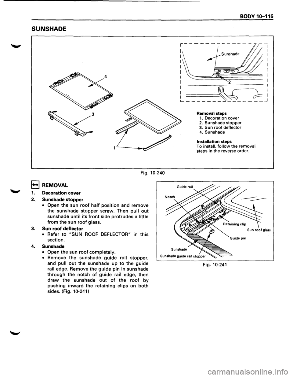
SUNSHADE
Fig. 10-240
1••1 REMOVAL
1. Decoration cover
2. Sunshade
stopper
• Open the sun roof half position and remove
the sunshade stopper screw. Then
pull out
sunshade until its front side protrudes a little
from the sun roof glass.
3. Sun roof deflector
• Refer to "SUN ROOF DEFLECTOR" in this
section.
4. Sunshade
• Open the sun roof completely.
• Remove the sunshade guide rail stopper,
and
pull out the sunshade up to the guide
rail edge. Remove the guide pin in sunshade
through the notch of guide rail edge, then
draw the sunshade out of the roof by
pushing inward the retaining clips on both
sides. (Fig.
10-241)
BODY 10-115
Removal steps 1. Decoration cover
2. Sunshade stopper 3. Sun roof deflector 4. Sunshade
Installation steps
To install, follow the removal steps in the reverse order.
Fig. 10-241
Page 1874 of 1928
10-116 BODY
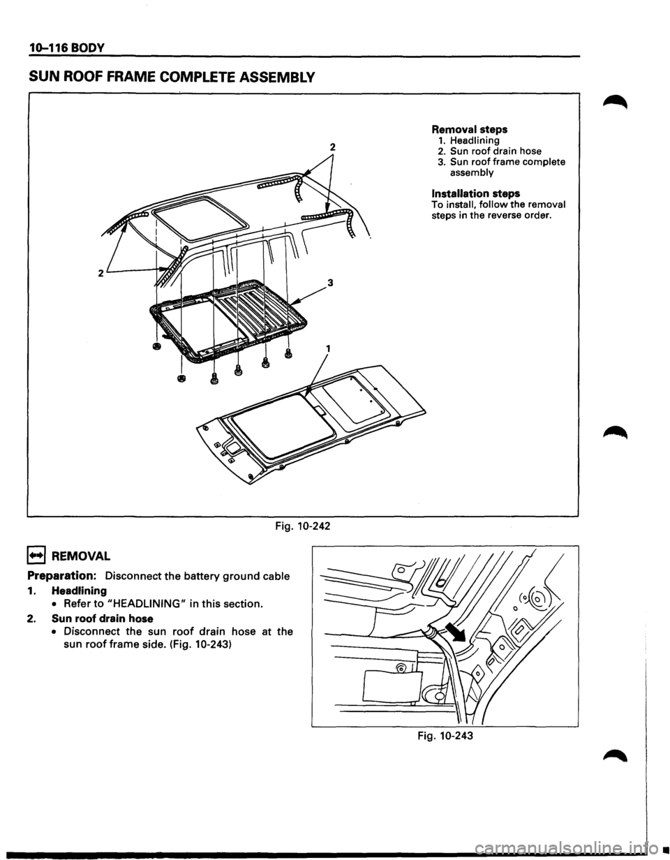
SUN ROOF FRAME COMPLETE ASSEMBLY
2
Fig. 10-242
1••1 REMOVAL
Preparation: Disconnect the battery ground cable
1. Headlining
• Refer to "HEADLINING" in this section.
2. Sun roof drain hose
• Disconnect the sun roof drain hose at the
sun
roof frame side. (Fig. 10-243)
Removal steps 1. Headlining 2. Sun roof drain hose 3. Sun roof frame complete
assembly
Installation steps To install, follow the removal steps in the reverse order.
Fig. 10-243
•
Page 1875 of 1928
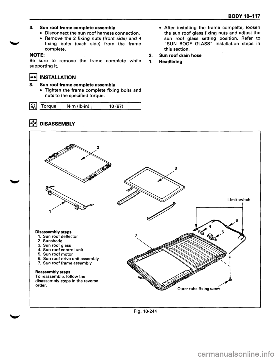
3. Sun roof frame complete assembly
• Disconnect the sun roof harness connection.
• Remove the 2 fixing nuts (front side) and 4
fixing bolts (each side) from the frame
complete.
NOTE:
Be sure to remove the frame complete while
supporting it.
I+•IINSTALLATION
3. Sun roof frame complete assembly
• Tighten the frame complete fixing bolts and
nuts
to the specified torque.
~~~ Torque N-m (lb-in) j
1•!•1 DISASSEMBLY
Disassembly steps 1. Sun roof deflector 2. Sunshade 3. Sun roof glass 4. Sun roof control unit 5. Sun roof motor
6. Sun roof drive unit assembly 7. Sun roof frame assembly
Reassembly steps To reassemble, follow the disassembly steps in the reverse
order.
10 (87)
7
BODY 10-117
• After installing the frame compelte, loosen
the sun roof glass fixing nuts and adjust the
sun
roof glass setting position. Refer to
"SUN ROOF GLASS" installation steps in
this section.
2. Sun roof drain hose
1. Headlining
Outer tube fixing screw
Limit switch
Fig. 10-244
Page 1876 of 1928
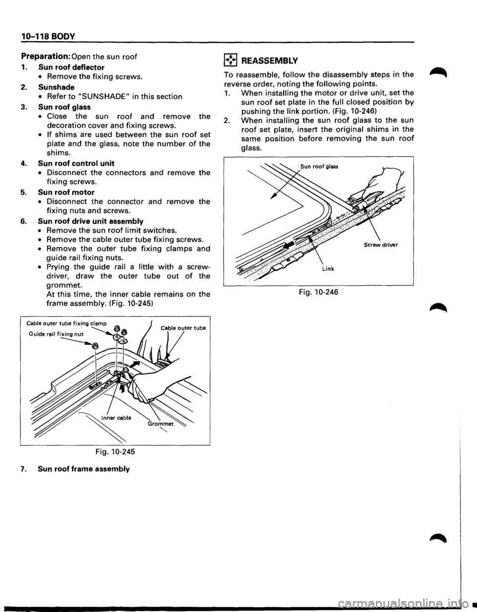
10-118 BODY
Preparation: Open the sun roof
1. Sun roof deflector
• Remove the fixing screws.
2. Sunshade
• Refer to "SUNSHADE" in this section
3. Sun roof glass
• Close the sun roof and remove the
decoration cover and
fixing screws.
• If shims are used between the sun roof set
plate and the glass, note the number of the
shims.
4. Sun roof control unit
• Disconnect the connectors and remove the
fixing screws.
5. Sun roof motor
• Disconnect the connector and remove the
fixing nuts and screws.
6. Sun roof drive unit assembly
• Remove the sun roof limit switches.
• Remove the cable outer tube fixing screws.
• Remove the outer tube fixing clamps and
guide rail fixing nuts.
• Prying the guide rail a little with a screw
driver,
draw the outer tube out of the
grommet.
At this time, the inner cable remains on the
frame assembly. (Fig. 10-245)
Cable outer tube
Fig. 10-245
7. Sun roof frame assembly
l•!•l REASSEMBLY
To reassemble, follow the disassembly steps in the
reverse order,
noting the following points.
1. When installing the motor or drive unit, set the
sun roof set plate in the full closed position by
pushing the link portion. (Fig. 10-246)
2. When installing the sun roof glass to the sun
roof set plate, insert the original shims in the
same
position before removing the sun roof
glass.
Screw driver
Link
Fig. 10-246
•
Page 1877 of 1928
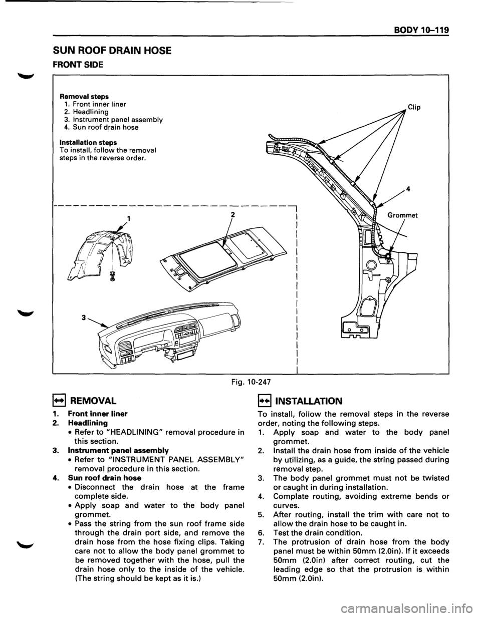
SUN ROOF DRAIN HOSE
FRONT SIDE
Removal steps 1. Front inner liner
2. Headlining 3. Instrument panel assembly 4. Sun roof drain hose
Installation steps
To install, follow the removal steps in the reverse order.
BODY 10-119
Fig. 10-247
B REMOVAL
1. Front inner liner
2. Headlining
• Refer to "HEADLINING" removal procedure in
this section.
3. Instrument panel assembly
• Refer to "INSTRUMENT PANEL ASSEMBLY"
removal procedure in this section.
4. Sun roof drain hose
• Disconnect the drain hose at the frame
complete side.
• Apply soap and water to the body panel
grommet.
• Pass the string from the sun roof frame side
through the drain port side, and remove the
drain hose from the hose fixing clips. Taking
care
not to allow the body panel grommet to
be removed together with the hose, pull the
drain hose only to the inside of the vehicle.
(The string
should be kept as it is.)
B INSTALLATION
To install, follow the removal steps in the reverse
order,
noting the following steps.
1. Apply soap and water to the body panel
grommet.
2. Install the drain hose from inside of the vehicle
by utilizing, as a guide, the string passed during
removal step.
3. The body panel grommet must not be twisted
or caught in during installation.
4. Complate routing, avoiding extreme bends or
curves.
5. After routing, install the trim with care not to
allow the drain hose to be caught in.
6. Test the drain condition.
7. The protrusion of drain hose from the body
panel must be within 50mm (2.0in). If it exceeds
50mm (2.0in) after correct routing, cut the
leading edge so that the protrusion is within
50mm (2.0in).
Page 1878 of 1928
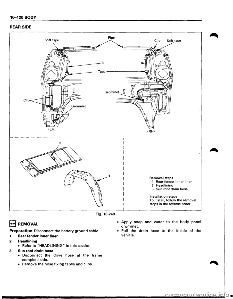
10-120 BODY
REAR SIDE
Soft tape Pipe
Clip
(LH)
2
1
Fig. 10-248
1••1 REMOVAL
Preparation: Disconnect
the battery ground cable
1. Rear fender inner liner
2. Headlining
•
Refer to "HEADLINING" in this section.
3. Sun roof drain hose
• Disconnect the drive hose at the frame
complete side.
• Remove the hose fixing tapes and clips.
--,
I
I
I
I
I
I
I
I
I
I
I
I
I
I
Soft tape
(RH)
Removal steps 1. Rear fender inner liner
2. Headlining 3. Sun roof drain hose
Installation steps To install, follow the removal steps in the reverse order.
• Apply soap and water to the body panel
grommet.
• Pull the drain hose to the inside of the
vehicle.
•
Page 1879 of 1928
I••! INSTALLATION
To install, follow the removal steps in the reverse
"-"' order, noting the following points.
1. Apply soap and water to the body panel
grommet.
2. Insert the drain hose from inside of vehicle,
restore routing, and fix with new soft tape and
clip.
If the grommet is removed during removal of
drain hose, insert the grommet into drain hose
from outside of vehicle, and install on the body
panel, avoiding any twisting.
3. After installing the drain hose, install the trim
while taking care not to crush the drain hose.
Also, care should be taken not to allow the
drain hose connected
to the pipe to be caught
in.
4. Test the drain condition.
5. The protrusion of drain hose from the body
panel must be within 50 mm (2.0 in). If it
exceeds 50 mm (2.0 in) after correct routing,
cut the
leading edge so that the protrusion is
within 50 mm (2.0 in).
BODY 10-121
Page 1880 of 1928
10-122 BODY
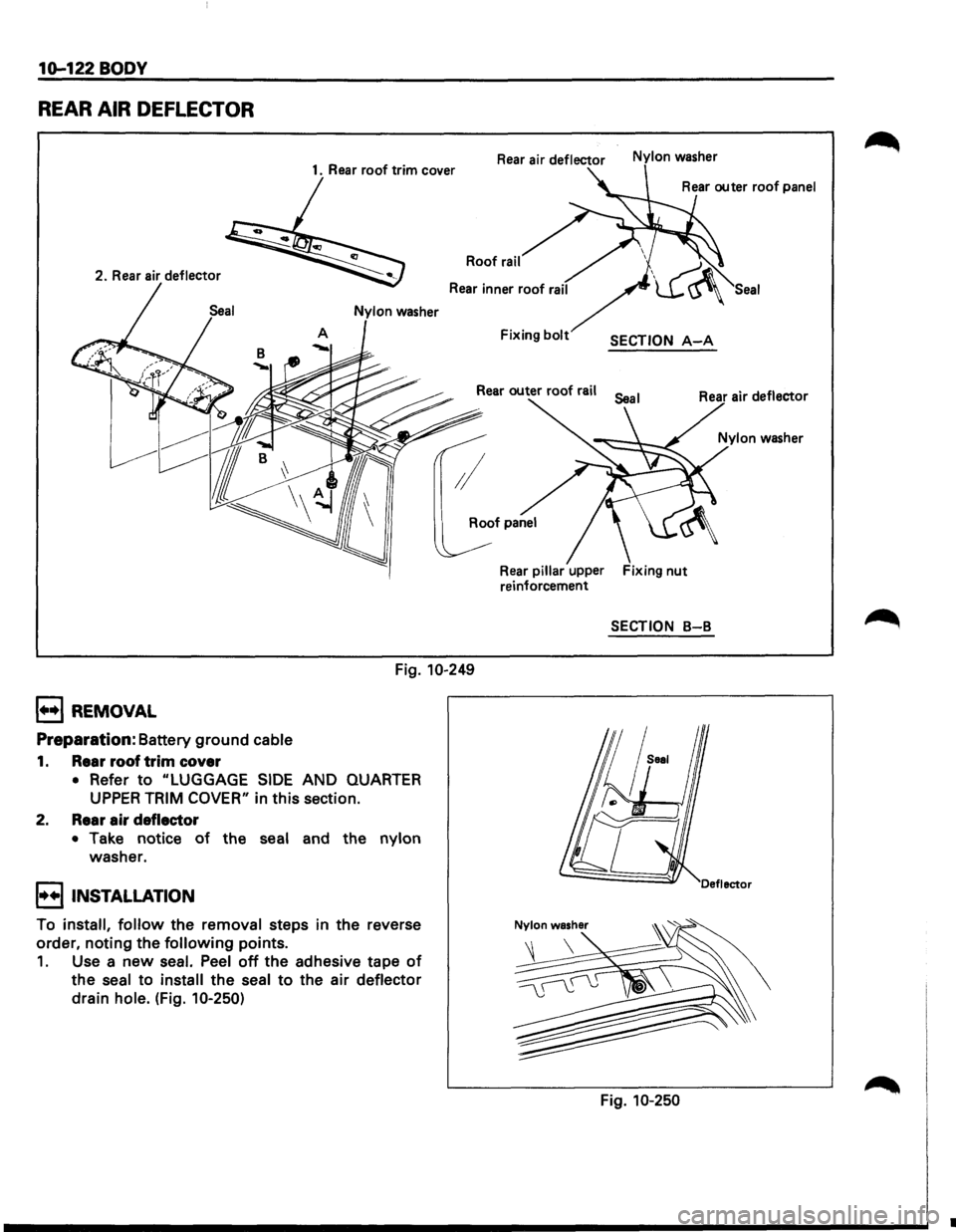
REAR AIR DEFLECTOR
1. Rear roof trim cover
2.
Rear air deflector
Rear air deflector Nylon washer
Roof rail
Fixing bolt SECTION A-A
Rear pillar upper Fixing nut reinforcement
SECTION B-B
Fig. 10-249
B REMOVAL
Preparation: Battery ground cable
1. Rear roof trim cover
• Refer to "LUGGAGE SIDE AND QUARTER
UPPER TRIM COVER" in this section.
2. Rear air deflector
• Take notice of the seal and the nylon
washer.
I••! INSTALLATION
To install, follow the removal steps in the reverse
order, noting the
following points.
1. Use a new seal. Peel off the adhesive tape of
the seal to install the seal to the air deflector
drain hole. (Fig.
10-250)
Fig. 10-250
Seal
•