ISUZU TROOPER 1995 Workshop Manual
Manufacturer: ISUZU, Model Year: 1995, Model line: TROOPER, Model: ISUZU TROOPER 1995Pages: 1928
Page 1841 of 1928
l••liNSTALLATION
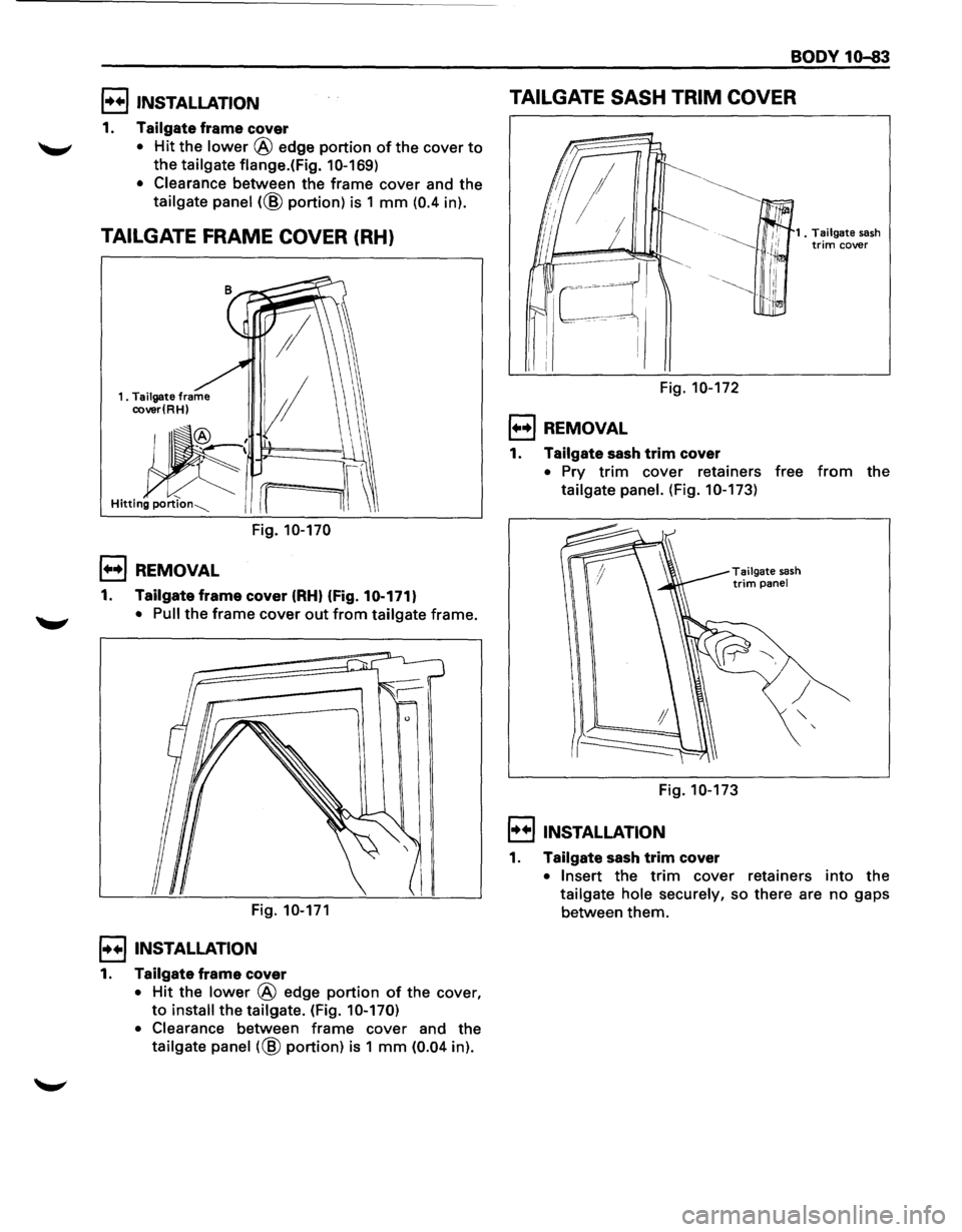
1. Tailgate frame cover
"-"' • Hit the lower @ edge portion of the cover to
the tailgate flange.( Fig. 1 0-169)
• Clearance
between the frame cover and the
tailgate panel (@ portion) is 1 mm (0.4 in).
TAILGATE FRAME COVER (RH)
Fig. 10-170
l••l REMOVAL
1. Tailgate frame cover (RH) (Fig.10-171)
• Pull the frame cover out from tailgate frame.
Fig.
10-171
I••! INSTALLATION
1. Tailgate frame cover
• Hit the lower @ edge portion of the cover,
to install the tailgate. (Fig. 10-170)
• Clearance
between frame cover and the
tailgate panel (@ portion) is 1 mm (0.04 in).
BODY 10-83
TAILGATE SASH TRIM COVER
Fig. 10-172
l••l REMOVAL
1. Tailgate sash trim cover
1 . Tailgate sash trim cover
• Pry trim cover retainers free from the
tailgate panel. (Fig. 10-173)
Tai I gate sash trim panel
Fig. 10-173
I••! INSTALLATION
1. Tailgate sash trim cover
• Insert the trim cover retainers into the
tailgate hole securely, so there are no gaps
between
them.
Page 1842 of 1928
1o-84 BODY
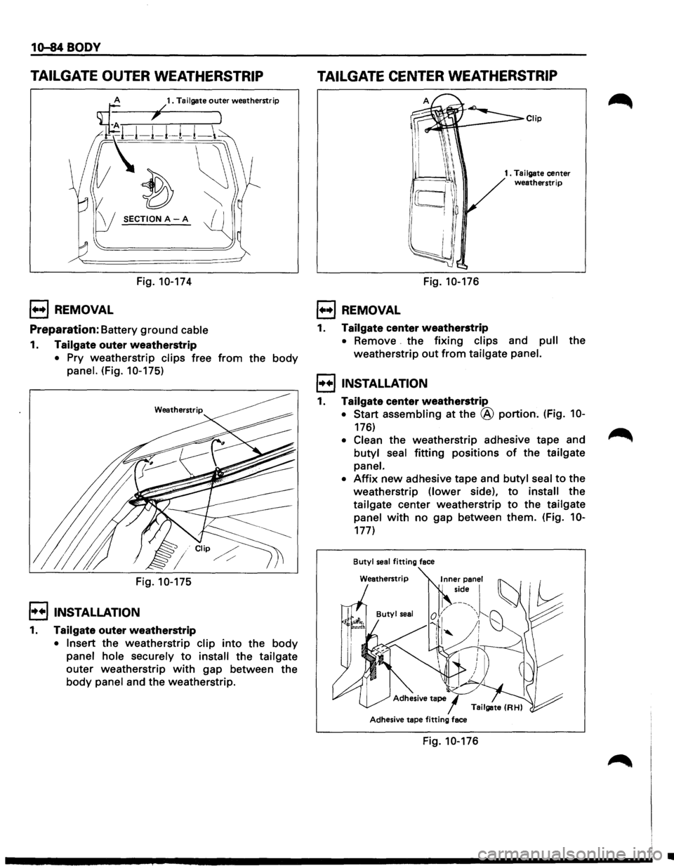
TAILGATE OUTER WEATHERSTRIP
SECTION A-A
Fig. 10-174
l••l REMOVAL
Preparation: Battery ground cable
1. Tailgate outer weatherstrip
• Pry weatherstrip clips free from the body
panel. (Fig. 10-175)
Fig. 10-175
l••IINSTALLATION
1. Tailgate outer weatherstrip
• Insert the weatherstrip clip into the body
panel hole securely to install the tailgate
outer weatherstrip with gap between the
body panel and the weatherstrip.
TAILGATE CENTER WEATHERSTRIP
Fig. 10-176
1••1 REMOVAL
1. Tailgate center weatherstrip
1 . Tailgate center weatherstrip
• Remove the fixing clips and pull the
weatherstrip
out from tailgate panel.
l•+IINSTALLATION
1. Tailgate center weatherstrip
• Start assembling at the @ portion. (Fig. 10-
176)
• Clean the weatherstrip adhesive tape and
butyl seal
fitting positions of the tailgate
panel.
•
Affix new adhesive tape and butyl seal to the
weatherstrip
(lower side), to install the
tailgate center weatherstrip
to the tailgate
panel
with no gap between them. (Fig. 10-
177)
Butyl seal fitting face
Adhesive
tape/ Tailgate (RH)
Adhesive
tape fitting face
Fig. 10-176
•
Page 1843 of 1928
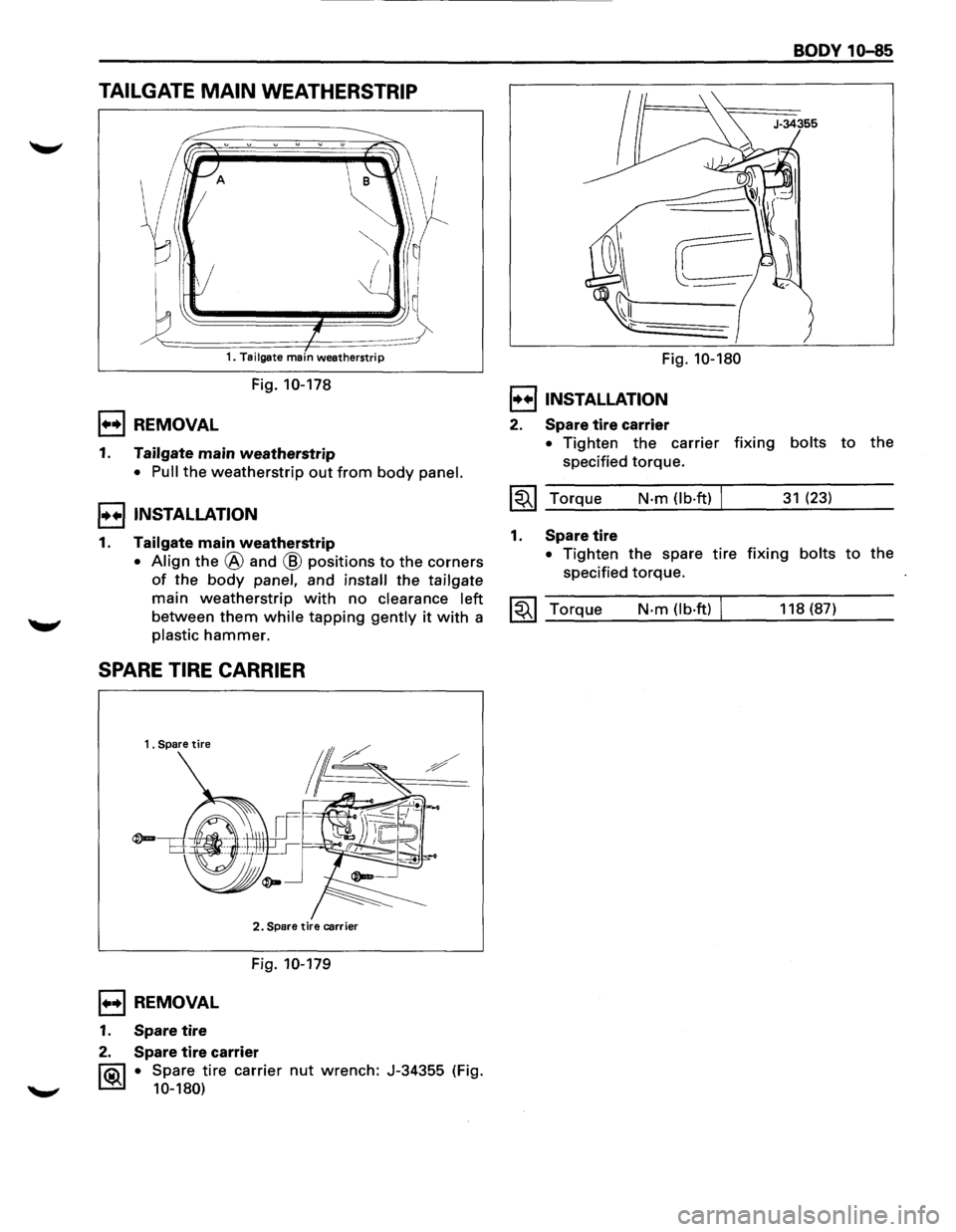
TAILGATE MAIN WEATHERSTRIP
~~~~~
A
~
1====1=-~ 1. Tailgate main weatherstrip
Fig. 10-178
1••1 REMOVAL
1. Tailgate main weatherstrip
• Pull the weatherstrip out from body panel.
I••IINSTALLATION
1. Tailgate main weatherstrip
• Align the @ and @ positions to the corners
of ~he body panel, and install the tailgate
mam weatherstrip with no clearance left
between them while tapping gently it with a
plastic hammer.
SPARE TIRE CARRIER
1 . Spare tire
2. Spare tire carrier
Fig. 10-179
1••1 REMOVAL
1. Spare tire
2. Spare tire carrier
~ • Spare tire carrier nut wrench: J-34355 (Fig.
10-180)
Fig. 10-180
I••IINSTALLATION
2. Spare tire carri,er
BODY 10-85
• Tighten the carrier fixing bolts to the
specified torque.
~~~ Torque N-m (lb-ft) I 31 (23)
1. Spare tire
• Tighten the spare tire fixing bolts to the
specified torque.
~~~ Torque N-m (lb·ft) I 118 (87)
Page 1844 of 1928
10-86BODY
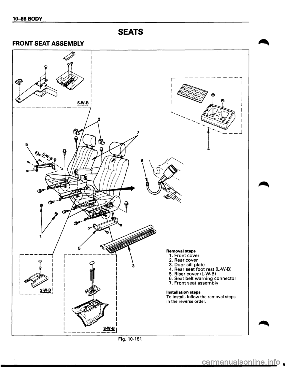
FRONT SEAT ASSEMBLY
~ : I
I I
1
,-----
1 0
: t
:~
~~,
I S·W·BI L ______ :J
I
I
I
I
I I I
I
I I
I S·W·B
r-----------
1 q
! 1 I ! ..
~~
I
I
I
I
I I
L _______ S·W·!J
SEATS
3
Fig.
10-181
Removal steps
1. Front cover 2.Rearcover 3. Door sill plate 4. Rear seat foot rest (l·W·B) 5. Riser cover (L·W·B) 6. Seat belt warning connector 7. Front seat assembly
Installation steps
To install, follow the removal steps
in the reverse order.
II
Page 1845 of 1928
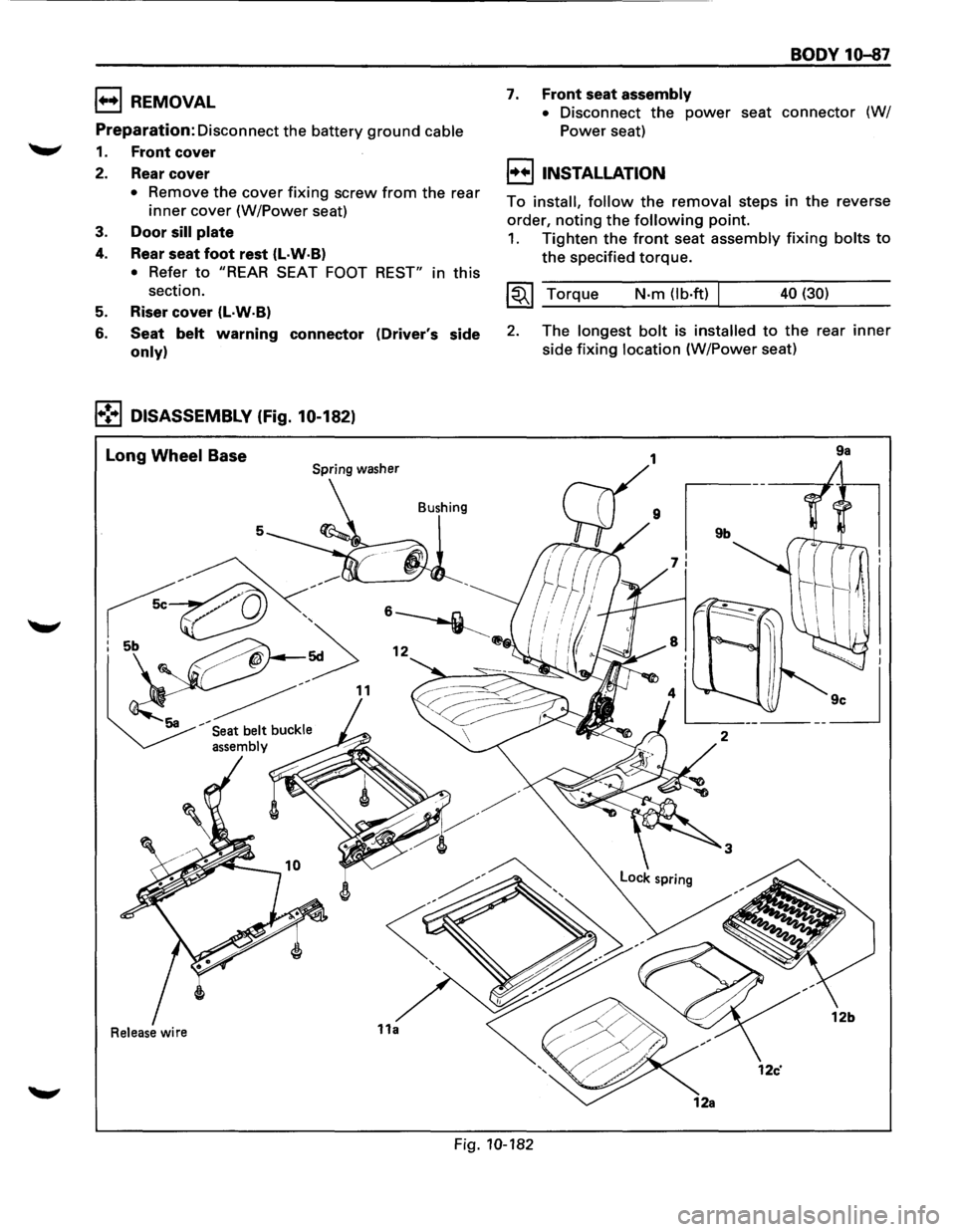
1++1 REMOVAL
Preparation:
Disconnect the battery ground cable
1. Front cover
2. Rear cover
• Remove the cover fixing screw from the rear
inner cover (W/Power seat)
3. Door sill plate
4. Rear seat foot rest (l·W·B)
• Refer to "REAR SEAT FOOT REST" in this
section.
5. Riser cover (L·W·B)
6. Seat belt warning connector (Driver's side
only)
1•!•1 DISASSEMBLY (Fig. 10-182)
Long Wheel Base Spring washer
Bushing
5
Release wire
BODY 10-87
7. Front seat assembly
•
Disconnect the power seat connector (W/
Power seat)
I++IINSTALLATION
To install, follow the removal steps in the reverse
order,
noting the following point.
1. Tighten the front seat assembly fixing bolts to
the specified torque.
~~~ Torque N-m (lb·ft) 40 (30)
2. The longest bolt is installed to the rear inner
side fixing location (W/Power seat)
9a
Fig. 10-182
Page 1846 of 1928
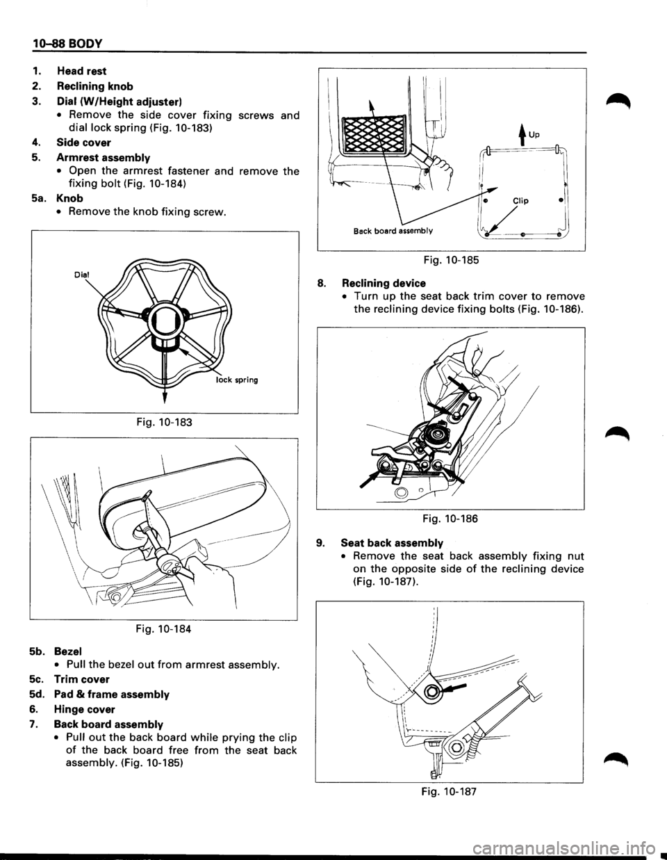
10-88 BODY
1. Head rest
2.
Reclining knob
3.
Dial (W/Height adjuster)
• Remove the side cover fixing screws and
dial lock spring (Fig. 10-183)
4. Side cover
5. Armrest assembly
• Open
the armrest fastener and remove the
fixing bolt (Fig. 10-184)
Sa. Knob
• Remove the knob fixing screw.
Dial
Fig. 10-183
Fig. 10-184
5b. Bezel
• Pull
the bezel out from armrest assembly.
5c. Trim cover
Sd. Pad & frame assembly
6. Hinge cover
7. Back board assembly
• Pull
out the back board while prying the clip
of the back board free from the seat back
assembly. (Fig. 10-185)
Back board assembly
Fig. 10-185
8. Reclining device
9.
• Turn up the seat back trim cover to remove
the reclining device fixing bolts (Fig. 10-186).
I I
Fig. 10-186
Seat back assembly
•
Remove the seat back assembly fixing nut
on the opposite side of the reclining device
(Fig.
10-187).
Fig. 10-187
Page 1847 of 1928
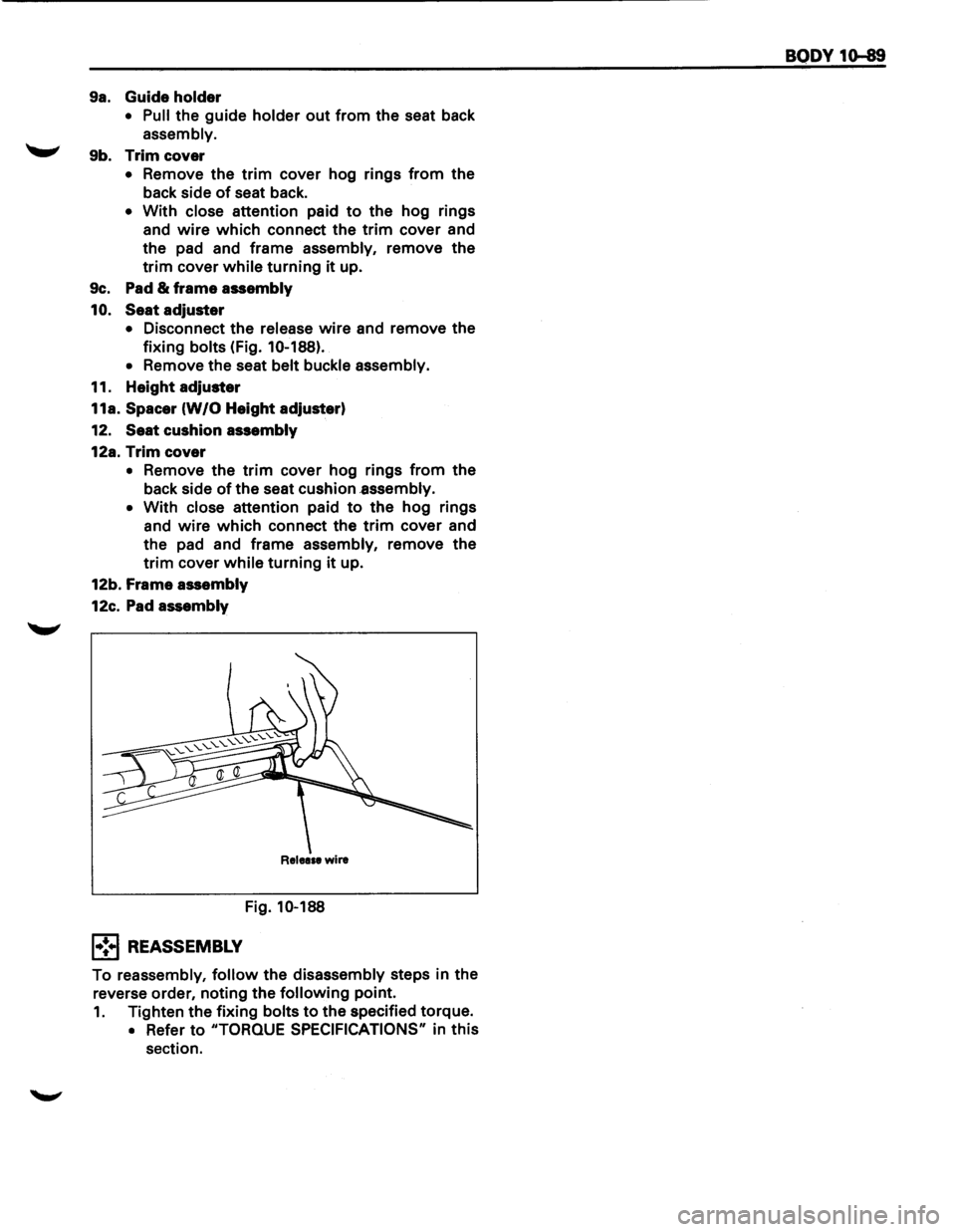
9a. Guide holder
• Pull the guide holder out from the seat back
assembly.
"-"' 9b. Trim cover
• Remove the trim cover hog rings from the
back side
of seat back.
• With close attention paid to the hog rings
and
wire which connect the trim cover and
the pad and frame assembly, remove the
trim cover while turning it up.
9c. Pad
& frame assembly
10. Seat adjuster
• Disconnect the release wire and remove the
fixing
bolts (Fig. 10-188).
•
Remove the seat belt buckle assembly.
11. Height adjuster
11a.
Spacer (W/0 Height adjuster)
12. Seat cushion assembly
12a.
Trim cover
• Remove the trim cover hog rings from the
back side
of the seat cushion .assembly.
• With close attention paid to the hog rings
and
wire which connect the trim cover and
the pad and frame assembly, remove the
trim cover while turning it up.
12b. Frame assembly
12c. Pad assembly
Release wire
Fig. 10-188
1•:.1 REASSEMBLY
To reassembly, follow the disassembly steps in the
reverse order, noting the
following point.
1. Tighten the fixing bolts to the specified torque.
• Refer to "TORQUE SPECIFICATIONS" in this
section.
BODY 1o-89
Page 1848 of 1928
1o-90 BODY
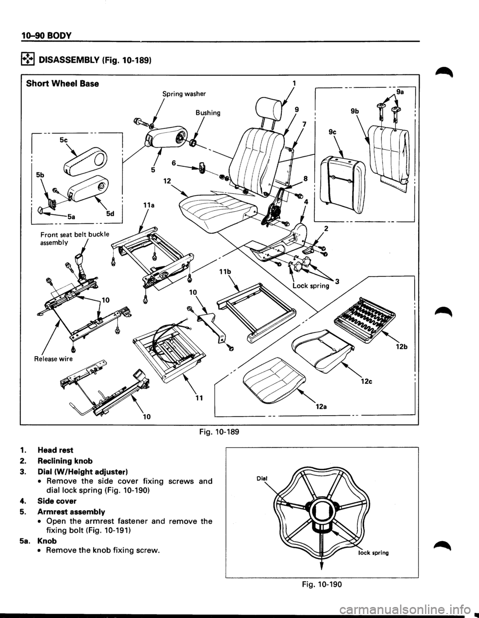
l•!•l DISASSEMBLY (Fig. 10-189)
Short Wheel Base
Spring washer
Front seat belt buckle
assembly
Release
wire
Fig. 10-189
1. Head rest
2.
Reclining knob
3. Dial (W /Height adjuster)
• Remove the side cover fixing screws and
dial lock spring (Fig. 10-190)
4. Side cover
5. Armrest assembly
• Open the armrest fastener and remove the
fixing bolt (Fig. 10-191)
5a. Knob
• Remove the knob fixing screw.
I
________ 1_2a-------~
Fig. 10-190
Page 1849 of 1928
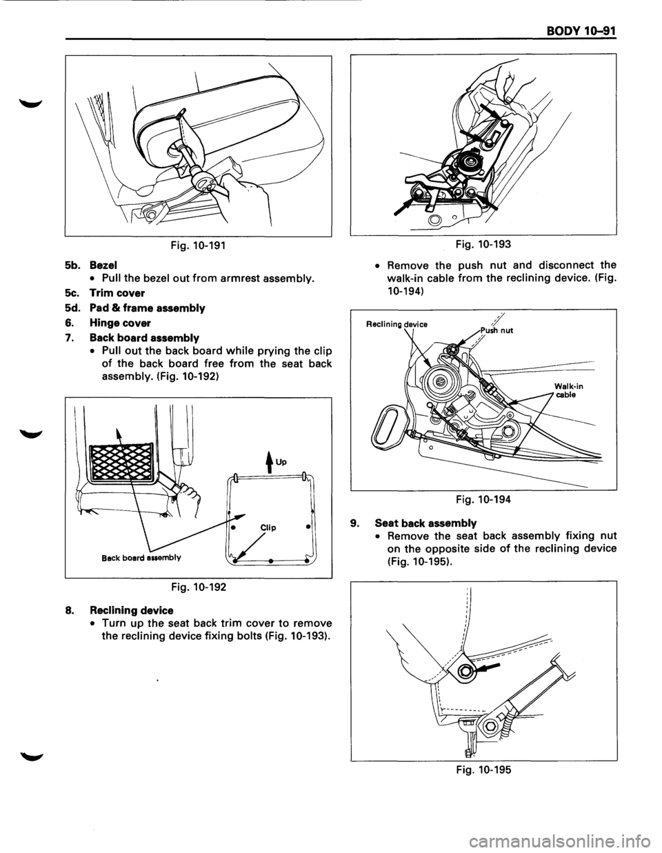
Fig. 10-191
5b. Bezel
• Pull
the bezel out from armrest assembly.
5c. Trim cover
5d. Pad
& frame assembly
6. Hinge cover
7. Back board assembly
• Pull
out the back board while prying the clip
of the back board free from the seat back
assembly. (Fig. 10-192)
•
Fig. 10-192
8. Reclining device
• Turn up the seat back trim cover to remove
the
reclining device fixing bolts (Fig. 10-193).
BODY 10-91
Fig. 10-193
•
Remove the push nut and disconnect the
walk-in cable from the reclining device. (Fig.
10-194)
Reclining device
Fig. 10-194
9. Seat back assembly
•
Remove the seat back assembly fixing nut
on the opposite side of the reclining device
(Fig.
10-195).
Fig. 10-195
Page 1850 of 1928
10-92 BODY
9a. Guide holder
• Pull the guide holder out from the seat back
assembly.
9b. Trim cover
• Remove the trim cover hog rings from the
back side
of seat back.
• With close attention paid to the hog rings
and
wire which connect the trim cover and
the pad and
frame assembly, remove the
trim cover while turning it up.
9c. Pad
& frame assembly
10.
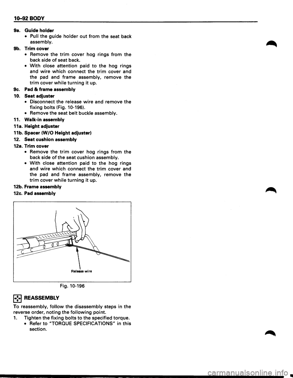
Seat adjuster
• Disconnect the release wire and remove the
fixing bolts (Fig. 10-196).
•
Remove the seat belt buckle assembly.
11. Walk-in assembly
11a. Height adjuster
11 b. Spacer (W /0 Height adjuster)
12. Seat cushion
assembly
12a. Trim cover
• Remove the trim cover hog rings from the
back side
of the seat cushion assembly.
•
With close attention paid to the hog rings
and
wire which connect the trim cover and
the pad and
frame assembly, remove the
trim cover while turning it up.
12b. Frame
assembly
12c. Pad assembly
Release wire
Fig. 10-196
1•!+1 REASSEMBLY
To reassembly, follow the disassembly steps in the
reverse order,
noting the following point.
1. Tighten the fixing bolts to the specified torque.
• Refer to "TORQUE SPECIFICATIONS" in this
section.
•