clutch ISUZU TROOPER 1995 Workshop Manual
[x] Cancel search | Manufacturer: ISUZU, Model Year: 1995, Model line: TROOPER, Model: ISUZU TROOPER 1995Pages: 1928
Page 1586 of 1928
98-2 CRUISE CONTROL
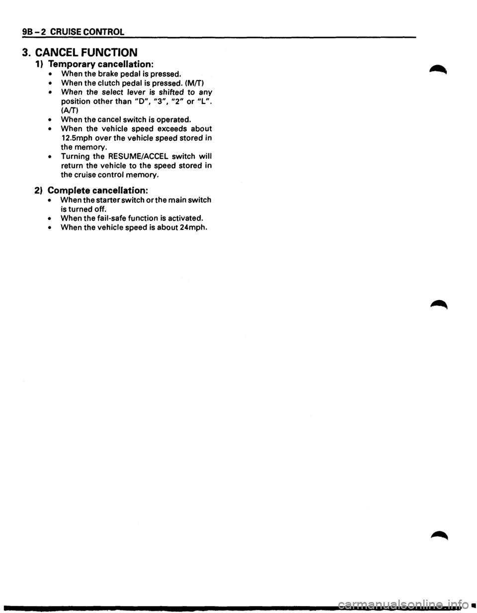
3. CANCEL FUNCTION
1) Temporary cancellation:
• When the brake pedal is pressed.
• When the clutch pedal is pressed. (Mfn
• When the select lever is shifted to any
position other than
"D", "3", "2" or "L".
(AfT')
• When the cancel switch is operated.
• When the vehicle speed exceeds about
12.5mph over the vehicle speed stored in
the memory.
• Turning the RESUME/ACCEL switch will
return the vehicle to the speed stored in
the cruise control memory.
2) Complete cancellation:
• When the starter switch or the main switch
is turned off.
• When the fail-safe function is activated.
• When the vehicle speed is about 24mph.
Ill
Page 1587 of 1928
, cCi" <0 CD I ....
( (
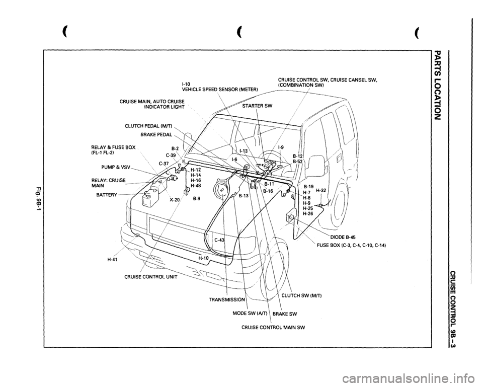
1-10
CRUISE CONTROL SW,
CRUISE
CANSEL SW,
!COMBINATION
SWl
VEHICLE
SPEED
SENSOR
!METER}
i
CRUISE MAIN, AUTO CRUISE
INDICATOR LIGHT
CLUTCH
PEDAL
IM[T)
~
. //
BRAKE PEDAL
~~
RELAY &
FUSE BOX
B-2
vi"""
(FL-1
FL-2}
C-3g\j;~
PUMP&VSV
RELAY:
CRUISE
MAIN BATTERY--
/
H-41
··,.
,:-,
\
·.,"-
~DIODE
8-45
'"-FUSE
BOX IC-3, C-4, C-10,
C-14)
CRUISE
CONTROL
MAIN
SW
(
~ ~ 0 n ~ 0 z
n ::D c c;; m n 0 ~ 0 r-fD OJ I w
Page 1592 of 1928
98-8 CRUISE CONTROL
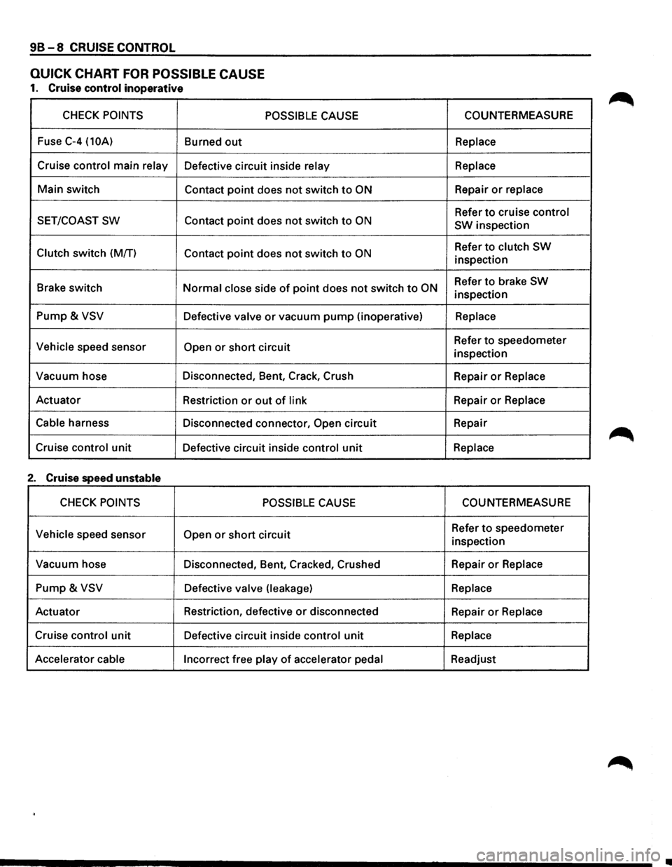
QUICK CHART FOR POSSIBLE CAUSE
1. Cruise control inoperative
CHECK POINTS POSSIBLE CAUSE
Fuse C-4 (10A) Burned out
Cruise control main relay Defective circuit inside relay
Main switch
Contact point does not switch to ON
SET/COAST SW Contact point does not switch to ON
Clutch switch (M/T)
Contact point does not switch to ON
Brake switch Normal close side of point does not switch to ON
Pump & VSV Defective valve or vacuum pump (inoperative)
Vehicle speed sensor Open or short circuit
Vacuum hose Disconnected, Bent, Crack, Crush
Actuator Restriction
or out of link
Cable
harness Disconnected connector, Open circuit
Cruise
control unit Defective circuit inside control unit
2. Cruise speed unstable
CHECK POINTS POSSIBLE CAUSE
Vehicle
speed sensor Open or short circuit
Vacuum hose
Disconnected, Bent, Cracked, Crushed
Pump & VSV Defective valve (leakage)
Actuator Restriction,
defective or disconnected
Cruise
control unit Defective circuit inside control unit
Accelerator cable
Incorrect free play of accelerator pedal COUNTERMEASURE
Replace
Replace
Repair or replace
Refer to cruise control
SW
inspection
Refer
to clutch SW
inspection
Refer
to brake SW
inspection
Replace
Refer to speedometer
inspection
Repair
or Replace
Repair or Replace
Repair
Replace
COUNTERMEASURE
Refer to speedometer
inspection
Repair
or Replace
Replace
Repair or Replace
Replace
Readjust
•
Page 1593 of 1928
-------------------
CRUISE CONTROL 98-9
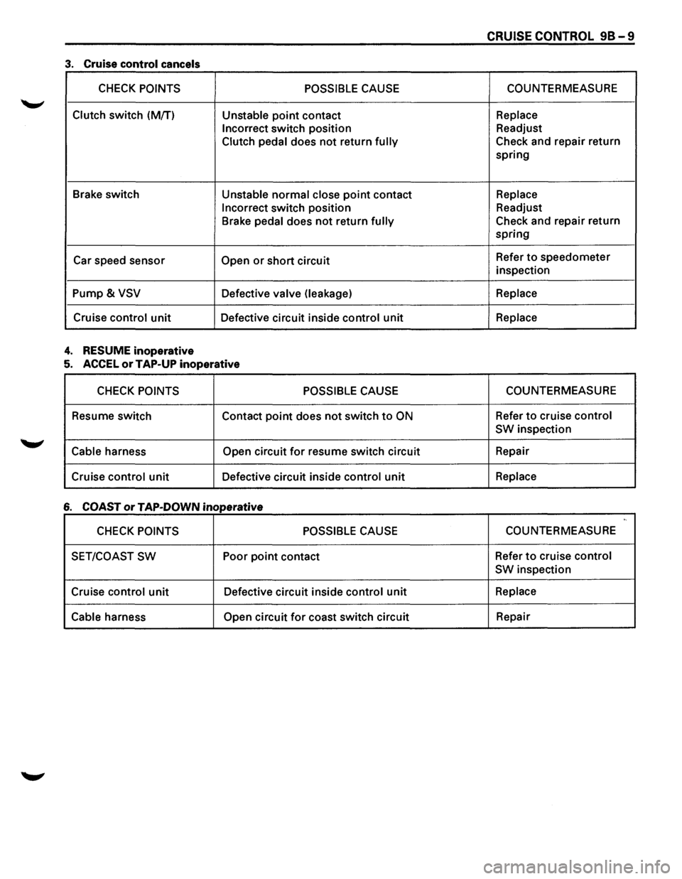
3. Cruise control cancels
CHECK POINTS POSSIBLE CAUSE COUNTERMEASURE
Clutch switch
(M/T) Unstable point contact Replace
Incorrect
switch position Readjust
Clutch
pedal does not return fully Check and repair return
spring
Brake switch
Unstable normal close point contact Replace
Incorrect
switch position Readjust
Brake
pedal does not return fully Check and repair return
spring
Car speed sensor
Open or short circuit Refer to speedometer
inspection
Pump& VSV Defective valve (leakage) Replace
Cruise control unit Defective circuit inside control unit Replace
4. RESUME inoperative
5. ACCEL or TAP-UP inoperative
CHECK POINTS POSSIBLE CAUSE COUNTERMEASURE
Resume switch
Contact
point does not switch to ON Refer to cruise control
SW
inspection
Cable harness Open circuit for resume switch circuit Repair
Cruise
control unit Defective circuit inside control unit Replace
6 COAST or TAP-DOWN inoperative ,,
CHECK POINTS POSSIBLE CAUSE COUNTERMEASURE
SET/COAST
SW Poor point contact Refer to cruise control
SW
inspection
Cruise
control unit Defective circuit inside control unit Replace
Cable
harness Open circuit for coast switch circuit Repair
Page 1594 of 1928
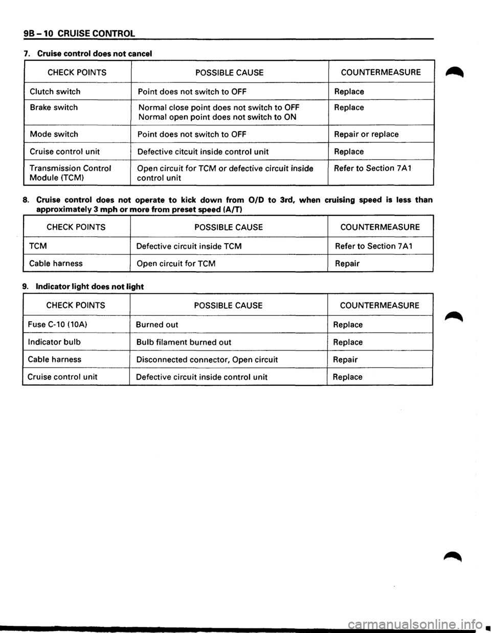
98-10 CRUISE CONTROL
7. Cruise control does not cancel
CHECK POINTS POSSIBLE CAUSE COUNTERMEASURE
Clutch switch Point does not switch to OFF Replace
Brake switch
Normal close point does not switch to OFF Replace
Normal open point does not switch to ON
Mode switch Point does not switch to OFF Repair or replace
Cruise control unit
Defective citcuit inside control unit Replace
Transmission Control Open circuit for TCM or defective circuit inside Refer to Section
7 A 1
Module (TCM) control unit
8. Cruise control does not operate to kick down from 0/D to 3rd, when cruising speed is less than
approximately 3 mph or more from preset speed (A/T)
CHECK POINTS POSSIBLE CAUSE COUNTERMEASURE
TCM Defective circuit inside TCM Refer
to Section 7 A 1
Cable harness Open circuit for TCM
Repair
9. Indicator light does not light
CHECK POINTS POSSIBLE CAUSE COUNTERMEASURE
Fuse
C-10 (10A) Burned out Replace
Indicator
bulb Bulb filament burned out Replace
Cable
harness Disconnected connector, Open circuit Repair
Cruise
control unit Defective circuit inside control unit Replace
..
Page 1600 of 1928
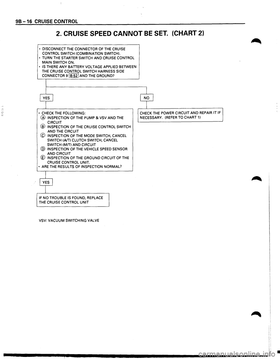
98 -16 CRUISE CONTROL
2. CRUISE SPEED CANNOT BE SET. (CHART 2)
• DISCONNECT THE CONNECTOR OF THE CRUISE
CONTROL SWITCH !COMBINATION SWITCH).
•
TURN THE STARTER SWITCH AND CRUISE CONTROL MAIN SWITCH ON.
• IS THERE ANY BATIERY VOLTAGE APPLIED BETWEEN
THE
CRUISE CONTROL SWITCH HARNESS SIDE
CONNECTOR 9IB-52I AND THE GROUND?
•
CHECK THE FOLLOWING:
@ INSPECTION OF THE PUMP & VSV AND THE
CIRCUIT @ INSPECTION OF THE CRUISE CONTROL SWITCH AND THE CIRCUIT
@ INSPECTION OF THE MODE SWITCH, CANCEL SWITCH !A/Tl CLUTCH SWITCH, CANCEL SWITCH (MIT} AND CIRCUIT @ INSPECTION OF THE VEHICLE SPEED SENSOR AND CIRCUIT @ INSPECTION OF THE GROUND CIRCUIT OF THE
CRUISE CONTROL UNIT. • ARE THE RESULTS OF INSPECTION NORMAL?
IF NO TROUBLE IS FOUND, REPLACE
THE
CRUISE CONTROL UNIT
VSV: VACUUM SWITCHING VALVE CHECK
THE
POWER CIRCUIT AND REPAIR IT IF
NECESSARY.
(REFER TO CHART 1)
•
Page 1604 of 1928
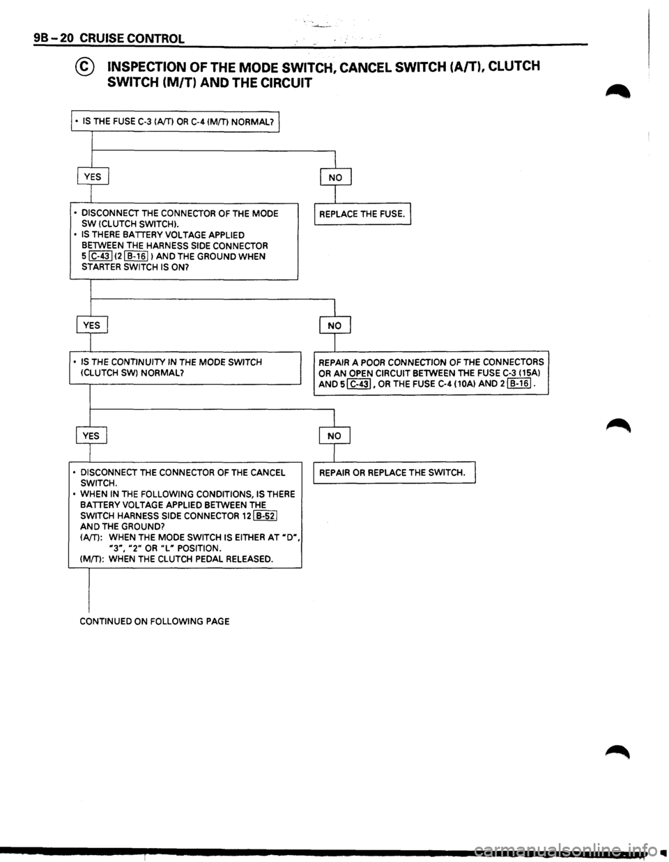
98-20 CRUISE CONTROL
@ INSPECTION OF THE MODE SWITCH, CANCEL SWITCH (A/T), CLUTCH
SWITCH
(M/T) AND THE CIRCUIT
• IS THE FUSE C-3 IA/TI OR C-4 IMfTI NORMAL?
• DISCONNECT THE CONNECTOR OF THE MODE SW (CLUTCH SWITCH).
• IS THERE BATTERY VOLTAGE APPLIED
BETWEEN THE HARNESS SIDE CONNECTOR SIC-431 121 B-1611 AND THE GROUND WHEN STARTER SWITCH IS ON?
• IS THE CONTINUITY IN THE MODE SWITCH !CLUTCH SW) NORMAL?
•
DISCONNECT THE CONNECTOR OF THE CANCEL SWITCH.
• WHEN IN THE FOLLOWING CONDITIONS, IS THERE BATTERY VOLTAGE APPLIED BETWEEN THE
SWITCH HARNESS SIDE CONNECTOR 121 B-521 AND THE GROUND?
(A/T): WHEN THE MODE SWITCH IS EITHER AT "D",
"3", "2" OR "L" POSITION. (MfTI: WHEN THE CLUTCH PEDAL RELEASED.
CONTINUED ON FOLLOWING PAGE
REPAIR A POOR CONNECTION OF THE CONNECTORS
OR AN OPEN CIRCUIT BETWEEN THE FUSE C-3 I 15A) AND 51 C-431, OR THE FUSE C-4 (10AI AND 21 B-161.
..
Page 1612 of 1928
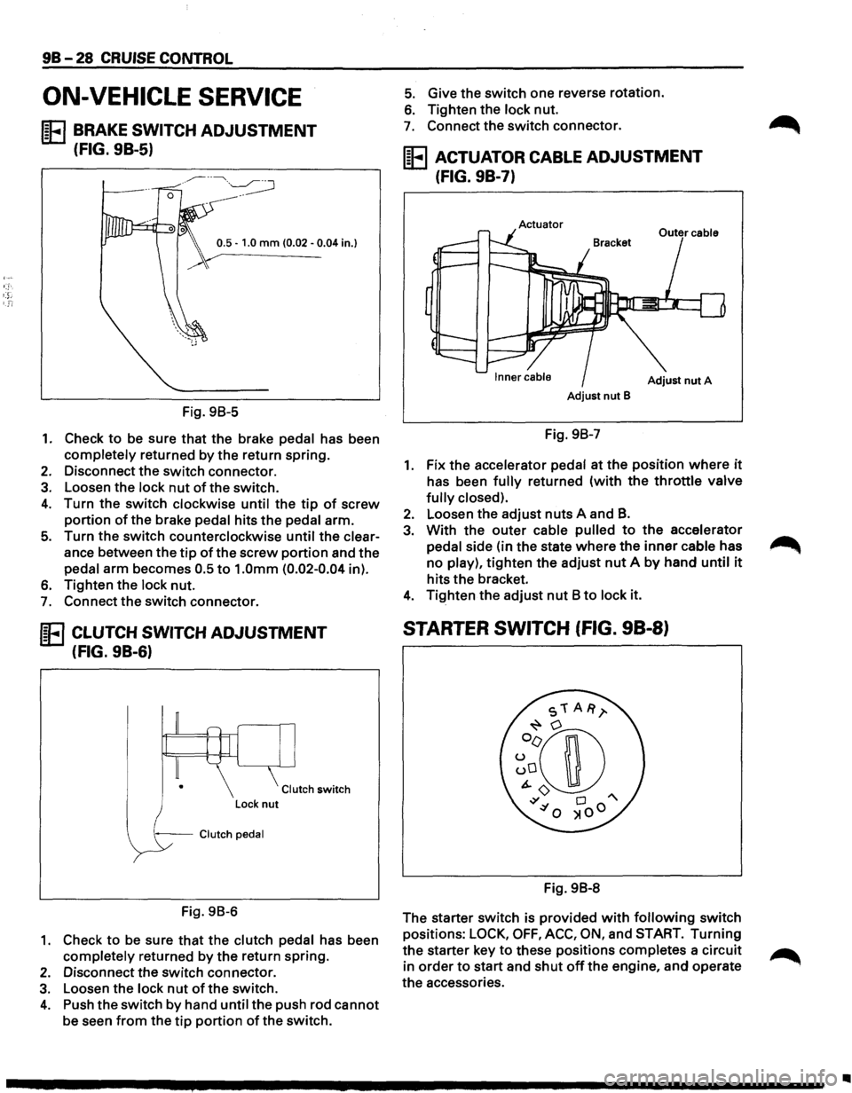
98-28 CRUISE CONTROL
ON-VEHICLE SERVICE
IE BRAKE SWITCH ADJUSTMENT
(FIG. 9B-5)
0.5 -1.0 mm (0.02 -0.04 in.}
Fig. 98-5
1. Check to be sure that the brake pedal has been
completely returned by the return spring.
2. Disconnect the switch connector.
3. Loosen the lock nut of the switch.
4. Turn the switch clockwise until the tip of screw
portion of the brake pedal hits the pedal arm.
5. Turn the switch counterclockwise until the clear
ance between the
tip of the screw portion and the
pedal arm becomes 0.5
to 1.0mm (0.02-0.04 in).
6. Tighten the lock nut.
7. Connect the switch connector.
IE CLUTCH SWITCH ADJUSTMENT
(FIG. 9B-6)
Clutch switch
--Clutch pedal
Fig. 98-6
1. Check to be sure that the clutch pedal has been
completely returned by
the return spring.
2. Disconnect the switch connector.
3. Loosen the lock nut of the switch.
4. Push the switch by hand until the push rod cannot
be seen from the tip portion of the switch.
5. Give the switch one reverse rotation.
6. Tighten the lock nut.
7. Connect the switch connector.
IE ACTUATOR CABLE ADJUSTMENT
(FIG. 9B-7)
Actuator
Adjust nut A
Adjust nut B
Fig. 98-7
1. Fix the accelerator pedal at the position where it
has been fully returned (with the throttle valve
fully closed).
2. Loosen the adjust nuts A and B.
3. With the outer cable pulled to the accelerator
pedal side (in the state
where the inner cable has
no play),
tighten the adjust nut A by hand until it
hits the bracket.
4. Tighten the adjust nut 8 to lock it.
STARTER SWITCH (FIG. 98-8)
Fig. 98-8
The starter switch is provided
with following switch
positions:
LOCK, OFF, ACC, ON, and START. Turning
the starter key to these positions completes a circuit
in
order to start and shut off the engine, and operate
the accessories.
Page 1617 of 1928
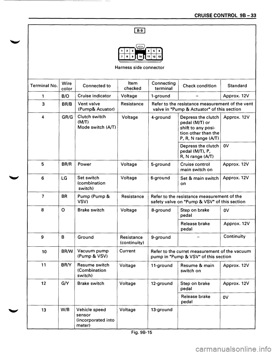
CRUISE CONTROL 98-33
[IT]
G?J 1 2 3 iiiill 4 5 8
7 8 9 10.n 11 12 13
Harness side connector
Terminal No. Wire
Connected to Item Connecting
Check condition Standard
color checked terminal
1 B/0 Cruise
indicator Voltage 1-ground -Approx. 12V
3 BR/B Vent valve
Resistance Refer to the resistance measurement of the vent
(Pump& Acuator)
valve in "Pump & Actuator• of this section
4
GR/G Clutch switch
Voltage 4-ground Depress the clutch Approx. 12V
(M/T) pedal (M/T)
or
Mode switch (AfT) shift to any posi-
tion other than the
P, R, N range (A/T)
Depress the clutch
ov
pedal (M/T), P,
R, N range (AfT)
5 BR/R Power
Voltage 5-ground Cruise control Approx.
12V
main switch on
6 LG Set switch Voltage 6-ground Set & main switch Approx.
12V
(combination on
switch)
7
BR Pump (Pump &
Resistance Refer to the resistance measurement of the
VSV) safety valve on "Pump & VSV" of this section
8
0 Brake switch Voltage 8-ground Step on brake ov
pedal
Release brake Approx.
12V
pedal
9 B Ground Resistance 9-ground
-Continuity
(continuity)
10 BR/W Vacuum pump Current
Refer to the curret measurement of the vacuum
(Pump &
VSV) pump in "Pump & VSV" of this section
11 BR!Y Resume switch
Voltage 11-ground Resume & main Approx.
12V
(Combination switch on
switch)
12 G/Y Brake
switch
Voltage 12-ground Step on brake Approx.
12V
pedal
Release brake ov
pedal
13 W/B Vehicle speed Voltage 13-ground
sensor (incorporated
into
meter)
Fig. 9B-15
Page 1620 of 1928
9B-36 CRUISE CONTROL
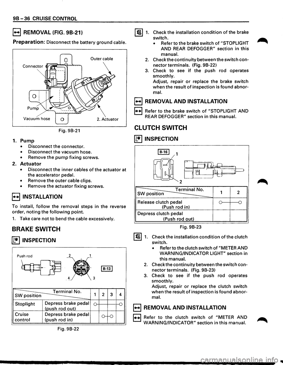
B REMOVAL (FIG. 98-21)
Preparation: Disconnect the battery ground cable.
Vacuum hose
Fig. 98-21
1. Pump
• Disconnect the connector.
• Disconnect the vacuum hose.
• Remove the pump fixing screws.
2. Actuator
• Disconnect the inner cables of the actuator at
the accelerator
pedal.
•
Remove the outer cable clips.
• Remove the actuator fixing screws.
E) INSTALLATION
To install, follow the removal steps in the reverse
order, noting
the following point.
1. Take care not to bend the cable excessively.
BRAKE SWITCH
~ INSPECTION
2 1
Push rod
~
~'
s ~ 1
Stoplight Depress brake pedal
(oush rod out)
Cruise Depress brake
pedal
control (push rod in)
Fig. 98-22
I B-131
2 3
o--o
4
~1. Check the installation condition of the brake
switch.
• Refer to the brake switch of "STOPLIGHT
AND REAR DEFOGGER" section in this
manual.
2. Check the continuity between the switch con
nector terminals. (Fig. 98-22)
3. Check to see if the push rod operates
smoothly. Adjust, repair
or replace the brake switch
when the result
of inspection is found abnor
mal.
B REMOVAL AND INSTALLATION
1·++·1 Refer to the brake switch of "STOPLIGHT AND
REAR DEFOGGER" section in this manual.
CLUTCH SWITCH
~INSPECTION
I B-161 1
rnll2a-~~
~ s 1 2
Release clutch pedal 0 ~ ~
(Push rod in)
Depress
clutch pedal
~1.
(Push rod out)
Fig. 98-23
Check the installation
condition of the clutch
switch.
• Refer to the clutch switch of "METER AND
WARNING/INDICATOR LIGHT" section in
this
manual.
2. Check the continuity between the switch con
nector terminals. (Fig. 98-23)
3. Check to see if the push rod operates
smoothly. Adjust, repair
or replace the clutch switch
when the result of inspection is found abnor
mal.
B REMOVAL AND INSTALLATION
1••1 Refer to the clutch switch of "METER AND ...-...
WARNING/INDICATOR"
section in this manual. ,...........