clutch ISUZU TROOPER 1995 Workshop Manual
[x] Cancel search | Manufacturer: ISUZU, Model Year: 1995, Model line: TROOPER, Model: ISUZU TROOPER 1995Pages: 1928
Page 1362 of 1928
8 -172 CHASSIS ELECTRICAL
CRUISE CONTROL
GENERAL DESCRIPTION
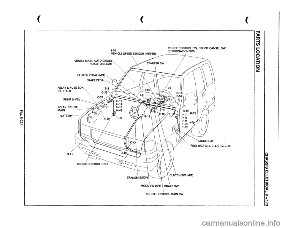
The circuit consists of the starter switch, cruise main switch, control switch, control unit, pump and actuator,
brake switch, clutch switch (M/T),
mode switch (Nf), vehicle speed sensor (incorporated into speedometer),
and indicator lights.
The cruise
control system keeps the vehicle running at a fixed speed until a signal canceling this speed is
received.
When the vehicle is in a running state with the main switch on, the battery voltage is applied to the control
unit. When a signal from the control switch is input into the control unit, while the vehicle is in this state, the
cruise control actuator is activated
to operate the system.
Also,
while the system is operating, the "AUTO CRUISE" indicator light in the instrument panel cluster lights
up.
Refer
to Section 98 "CRUISE CONTROL" for detail.
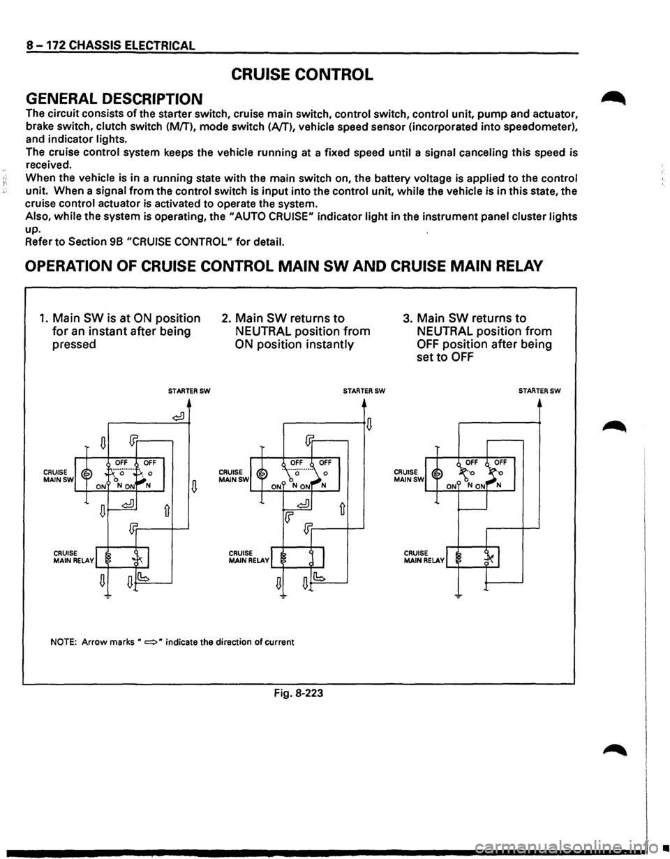
OPERATION OF CRUISE CONTROL MAIN SW AND CRUISE MAIN RELAY
1. Main SW is at ON position
for an instant after being
pressed
CRUISE MAINSW
n m
OFF OFF
~~ . !-':··a··---
~: 0 ON NON
n~
£Jr
CRUIS MAIN ~ELAvl .c~ I
n n(b
-
STARTERSW
¢:!)
fi
2. Main SW returns to
NEUTRAL position from
ON position instantly
CRUISE MAINSW
CRUISE MAIN RELAY
STARTERSW
NOTE: Arrow marks H c:::::> H indicate the direction of current
Fig. 8·223
3. Main SW returns to
NEUTRAL position from
OFF position after being
set
to OFF
CRUISE MAINSW
CRUISE MAIN RELAY
STARTERSW
..
Page 1363 of 1928
"TI ~· 00 I N N .,..
(
(
1-10 VEHICLE
SPEED
SENSOR
(METER!
CRUISE
CONTROL
SW,
CRUISE
CANSEL
SW,
(COMBINATION SWl
CRUISE
MAIN, AUTO
CRUISE
INDICATOR
LIGHT
'"
CLUTCH
PEDAL
(MfTI
BRAKE
PEDAL
RELAY
& FUSE
BOX
(FL-1
FL-2) PUMP
& VSV-------__
BATTERY
. '/
)",...
H-41
CRUISE
CONTROL
UNIT
·""·
'~~/{' /l/
'
4/
·,,_
DIODE
B-45
FUSE
BOX
(C-3,
C-4,
C-10,
C-14)
CRUISE
CONTROL
MAIN
SW
(
~ ::u ~ r-0 (") ~ 0 z
0 ::t > (/) (/) a; m ,.. m !l ::D 0 )> reo I ... ..... w
Page 1460 of 1928
8-270 CHASSIS ELECTRICAL
ANTI-THEFT SYSTEM
GENERAL DESCRIPTION .......
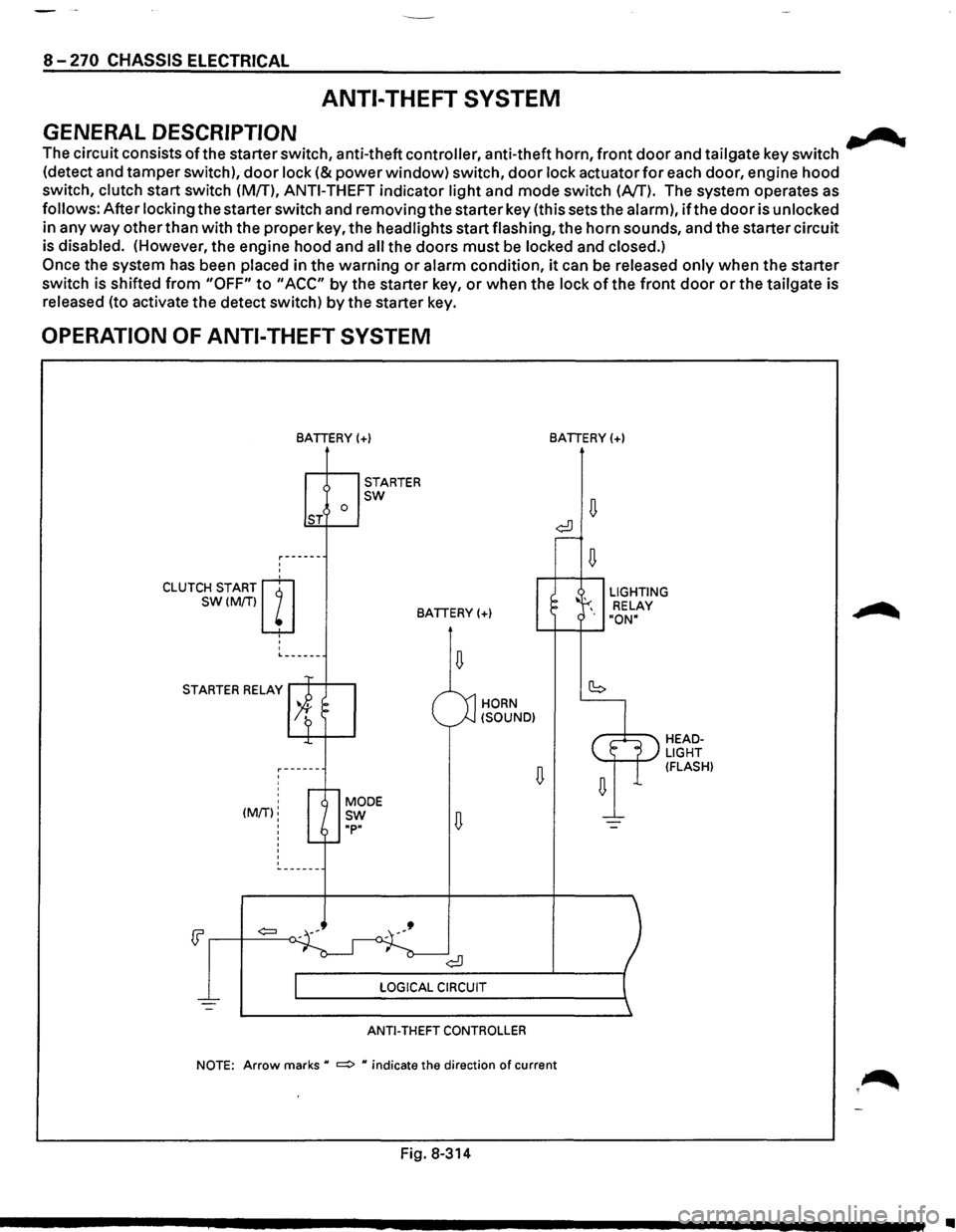
The circuit consists ofthe starter switch, anti-theft controller, anti-theft horn, front door and tailgate key switch
(detect and tamper switch),
door lock (&power window) switch, door lock actuator for each door, engine hood
switch, clutch start switch (MfT),
ANTI-THEFT indicator light and mode switch (AfT). The system operates as
follows: After locking the starter switch and removing the starter key (this sets the alarm),
ifthe door is unlocked
in any
way other than with the proper key, the headlights start flashing, the horn sounds, and the starter circuit
is disabled. (However,
the engine hood and all the doors must be locked and closed.)
Once the system has been placed in the warning or alarm condition, it can be released only when the starter
switch is shifted
from "OFF" to "ACC" by the starter key, or when the lock of the front door or the tailgate is
released (to activate the detect switch)
by the starter key.
OPERATION OF ANTI-THEFT SYSTEM
'
'
CLUTCH START m
SW(M/Tiw
' '
'
BATIERY(+)
0 ST
STARTER sw
BATIERY(+)
L------
STARTER RELAY
' ' (MIT):
'
'
'
HORN
(SOUND)
ANTI-THEFT CONTROLLER
BATIERY(+)
LIGHTING
RELAY
"ON"
HEADLIGHT (FLASH)
NOTE: Arrow marks u ~ u indicate the direction of current
Fig. 8-314
•
Page 1474 of 1928
8-284 CHASSIS ELECTRICAL
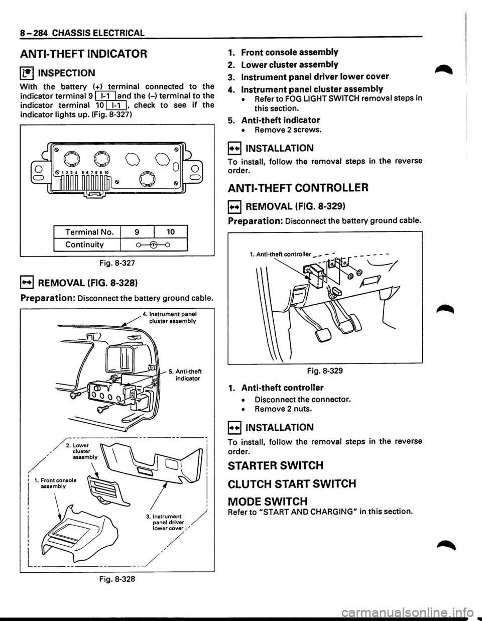
ANTI-THEFT INDICATOR
~ INSPECTION
With the battery (+) terminal connected to the
indicator
terminal 9 ~l'ld the H terminal to the
indicator
terminal 10[EIJ, check to see if the
indicator
lights up. (Fig. 8-327)
Terminal No. 9 10
Continuity
Fig. 8-327
B REMOVAL (FIG. 8-328)
Preparation: Disconnect the battery ground cable.
4. Instrument panel cluster assembly
-====-==============~!!;!;::,..
Fig. 8-328
5. Anti-theft
indicator
1. Front console assembly
2. lower cluster assembly
3. Instrument panel driver lower cover
4. Instrument panel cluster assembly
• Refer to FOG LIGHT SWITCH removal steps in
this section.
5. Anti-theft indicator
• Remove 2 screws.
B INSTALLATION
To install, follow the removal steps in the reverse
order.
ANTI-THEFT CONTROLLER
B REMOVAL (FIG. 8-329)
Preparation: Disconnect the battery ground cable.
Fig. 8-329
1. Anti-theft controller
• Disconnect the connector.
• Remove 2 nuts.
B INSTALLATION
To install, follow the removal steps in the reverse
order.
STARTER SWITCH
CLUTCH START SWITCH
MODE SWITCH
Refer to "START AND CHARGING" in this section.
Page 1478 of 1928
8-288 CHASSIS ELECTRICAL
METER AND WARNING/INDICATOR LIGHT
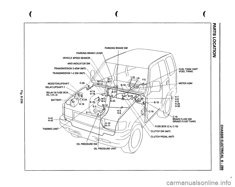
GENERAL DESCRIPTION
The circuit consists of the starter switch, meter assembly, vehicle speed sensor, clutch switch, transmission
switch, lighting switch,
turn signal switch, thermo unit, oil pressure unit, Engine Control Module, fuel tank unit,
4WD
SW, oil pressure switch, parking brake switch, brake fluid switch, seat belt switch and illumination
controller.
The meter ASM contains the speedometer, tachometer, voltmeter, engine coolant temperature gauge, oil
pressure gauge, fuel gauge and warning/indicator lights.
The meter warning/indicator lights and
their bulb sockets are a unit, they are installed from the back of the
speedometer assembly.
Page 1479 of 1928
::!!
(
(
PARKING
BRAKE
SW
PARKING
BRAKE
LEVER
VEHICLE
SPEED
SENSOR
4WD
INDICATOR
SW,
~
' '
/;~>
TRANSMISSION
3-4SW
IMJT)
"vf;/
RESISTOR;UPSHIFT
."
RELAY;UPSHIFT-1
~":'""
RELAY
& FUSE
BOX-_
(FL-1
,FL-21 BA.
TTERY--.;:;4"~
H-41 H-42
-----;1-"'.,.,-~
THERMO
UNIT
FUEL
TANK
UNIT
(FUEL
TANK)
METERASM
~
16)
1 /
1
(
H-7
/'1'-J
? I n
H-8 H-9 H-25
H-26 C..15 BRAKE
FLUID
SW
(BRAKE
FLUID
TANK}
FUSE
BOX
IC-4,
C-10}
\CLUTCH
SW
(M/T)
CLUTCH
PEDAL
(Mm
(
~ ::xs ~ r-0 0 ~ -0 2
(") :X: ~ en (i) m rm (") ~ g roo I ~
Page 1520 of 1928
8-330 CHASSIS ELECTRICAL
B INSTALLATION TRANSMISSION SWITCH
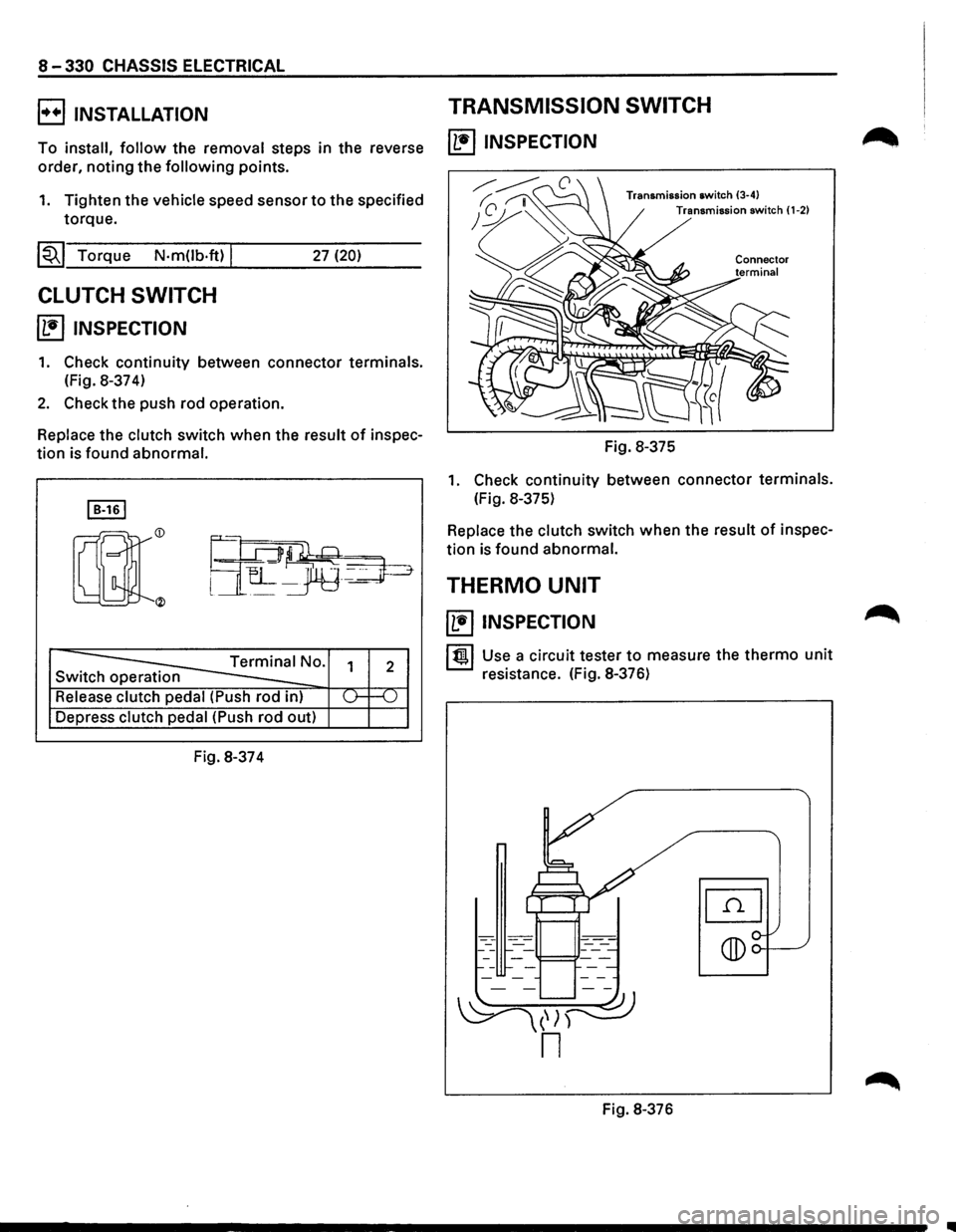
To install, follow the removal steps in the reverse ll•IINSPECTION
order, noting the following points.
1. Tighten the vehicle speed sensor to the specified
torque. Transmission switch (1-2)
~~~ Torque N·mUb·ft) j
CLUTCH SWITCH
~ INSPECTION
27 (20)
1. Check continuity between connector terminals.
(Fig. 8-37 4)
2. Check the push rod operation.
Replace the clutch switch when the result of inspec-
tion is found abnormal. Fig. 8-375
1. Check continuity between connector terminals.
I B-161 (Fig. 8-375)
Switch operation
Depress
clutch pedal (Push rod out)
Fig. 8-374
Replace the clutch switch when the result of inspec
tion is found abnormal.
THERMO UNIT
~ INSPECTION
11!!.1 Use a circuit tester to measure the thermo unit
resistance. (Fig. 8-376)
Fig. 8-376
Page 1529 of 1928
'"T1 cO' co w
RELAY
& FUSE
BOX
(FL-11
RELAY:
NC
COMPRESSOR
BLOWER
MOTOR
RELAY:
NCTHERMOSTAT
,,-;~
H-42'
NC:
AIR
CONDITIONING
(
PRESSURE
SW
RECEIVER
DRIER
B-19
FUSE
BOX
(C-19,
C-201
B-36 RELAY;
HEATER
& NC
NCSW FAN
SW
AND
HEATER
BEZEL
ILLUMINATION
LIGHT
(
MAGNETIC
CLUTCH
INC
COMPRESSOR)
;g ::0 ~ r-0 0 ~ 0 2
n :::J: )> en en Cii m rm ~ ::u n )> r-eo I w ~ ...a
Page 1532 of 1928
8-340 CHASSIS ELECTRICAL
HEATER AND AIR CONDITIONING
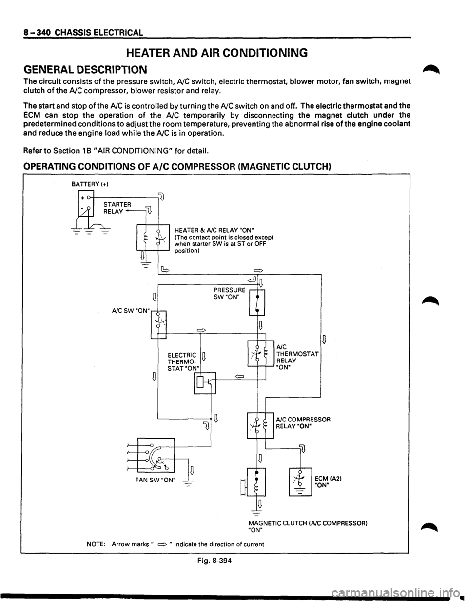
GENERAL DESCRIPTION
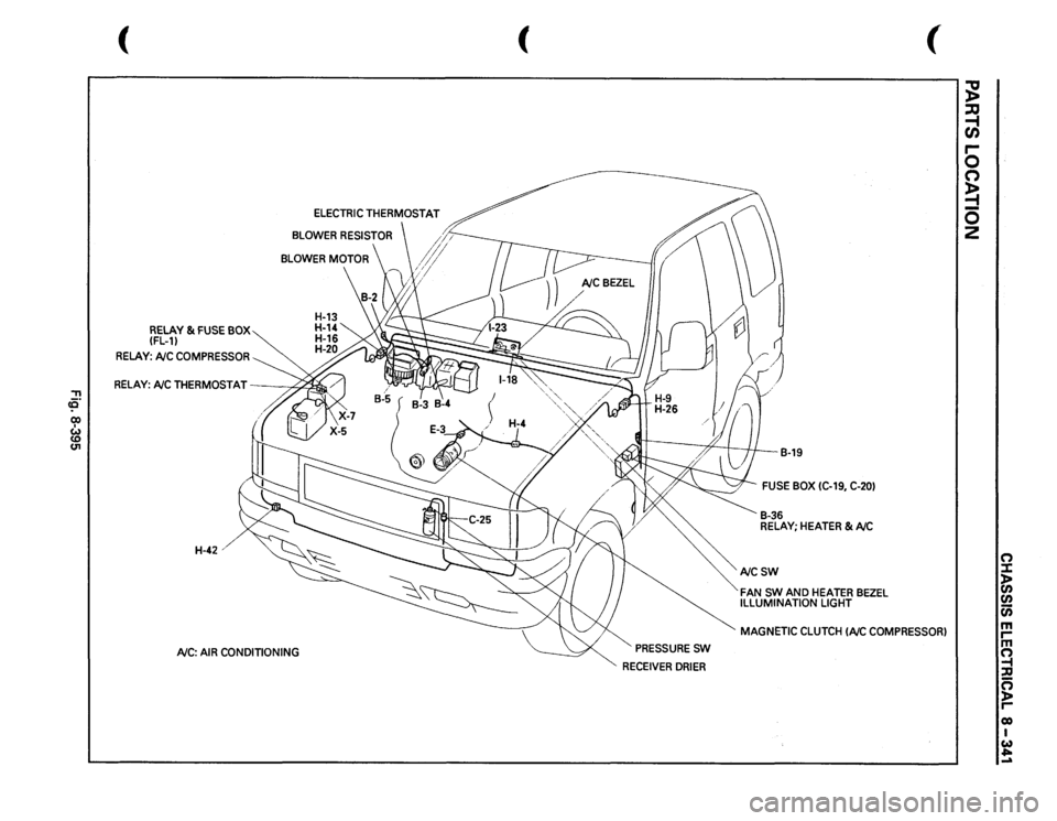
The circuit consists of the pressure switch, NC switch, electric thermostat, blower motor, fan switch, magnet
clutch of the NC compressor, blower resistor and relay.
The start and stop of the NC is controlled by turning the NC switch on and off. The electric thermostat and the
ECM can stop the operation of the NC temporarily by disconnecting the magnet clutch under the
predetermined conditions
to adjust the room temperature, preventing the abnormal rise of the engine coolant
and reduce the engine load while the NC is in operation.
Refer
to Section 18 "AIR CONDITIONING" for detail.
OPERATING CONDITIONS OF A/C COMPRESSOR (MAGNETIC CLUTCH)
BATIERY(+)
--
~
A/C SW "ON"
~
HEATER & A/C RELAY "ON"
(The contact point is closed except
when starter SW is at ST or OFF position)
(S =:>
¢:!]
PRESSURE D
SW"ON"
¢:::l
~ FAN SW"ON"
u A/C THERMOSTAT
RELAY
"ON"
A/C COMPRESSOR
RELAY"ON"
ECM IA2l "ON"
MAGNETIC
CLUTCH lAIC COMPRESSOR)
"ON"
NOTE:
Arrow marks" =:> " indicate the direction of current
Fig. 8-394
~
1111
Page 1585 of 1928
---------------~-~---
CRUISE CONTROL 9B-1
SECTION 98
CRUISE CONTROL
CONTENTS
General description ................................ .
Parts location .......................................... .
Circuit diagram ....................................... .
Diagnosis ................................................. .
On-vehicle service ................................. ..
Brake switch adjustment ................ ..
Clutch switch adjustment ................ .
Actuator
cable adjustment .............. .
Starter switch ................................... .
Cruise control main switch .............. .
GENERAL DESCRIPTION
98-1
9B-3
98-4
9B-7
98-28
9B-28
9B-28
9B-28
9B-28
9B-30 Cruise
control
switch
(combination switch) ........................ 98-31
Cruise control unit .......................... ... 9B-32
Pump
& actuator .................. .............. 9B-34
Brake switch ....................................... 9B-36
Clutch switch .............................. ....... 9B-36
Mode switch .. .. .. .. .. .. .. .. .. .. .. .. .. .. .. .. .. .. .. . 9B-37
Vehicle speed sensor
(incorporated in speedometer) ......... 9B-38
Diode
.. .. .. .. .. .. . .. .. .. .. .. . .. .. .. .. .. .. .. .. .. .. . .. .. .. 9B-38
Cruise control main relay .................. 9B-39
The circuit consists of the starter switch, cruise control main switch, cruise control switch, cruise control unit,
pump &actuator, brake switch, clutch switch (M/T), mode switch (A/T), vehicle speed sensor (incorporated into
the speedometer) and indicator light.
The cruise control keeps
the vehicle running at a fixed speed until a signal canceling this fixed speed is received.
When the main switch "AUTO CRUISE" is turned on with the vehicle in the running mode, the battery voltage
is applied
to the control unit. When a signal from the control switch is input to the control unit while the vehicle
is in this state, the cruise control actuator is activated to operate the system .
.._, Also, while the system is operating, the "AUTO CRUISE" indicator light in the indicator box lights up.
1. SET /COAST SWITCH FUNCTION
1) SET function: When the SET/COAST switch
is pressed and released
with the main switch
on, the speed at
which the vehicle is running
at that moment is stored in the memory, and
the vehicle
automatically runs at the speed
stored.
2) COAST-DOWN function: When the SET/
COAST switch is kept on while the vehicle in
running, the vehicle decelerates
during that
time. The speed at which vehicle is running
when the control switch is turned off is stored
in the
memory, and the vehicle automatically
returns
to the stored speed.
3) Tap-down function: When the SET/COAST
switch is turned on and off instantaneously
while the vehicle is running, the vehicle decel
erates a mile for each on/off operation. The
vehicle speed at
which the vehicle was run
ning when the SET/COAST was turned off last
is stored in the
memory, and the vehicle auto
matically returns to this stored speed.
2. RESUME/ ACCEL SWITCH FUNC
TION
1) Resume function: When the RESUME/
ACCEL switch is turned
on/off after the system
is
temporarily deactivated by pressing the
brake or clutch pedal while the vehicle is
running,
the vehicle resumes. The speed
stored before the system
was released.
2) Accelerate function: When the RESUME/
ACCEL switch is kept on after the system is
released completely, the vehicle accelerates
its speed
during that time. The vehicle speed
at
which the vehicle was running when the
switch
was turned off is stored in the memory,
and the vehicle automatically returns to this
speed.
3) Tap-up function: When the RESU ME/ACCEL
switch is
turned on and off instantaneously
while the vehicle is running, the vehicle decel
erates a mile for each on/off operation. The
vehicle speed at
which the vehicle was run
ning when the switch was turned off last is
stored in the
memory, and the vehicle auto
matically returns to this stored speed.