clutch ISUZU TROOPER 1995 Workshop Manual
[x] Cancel search | Manufacturer: ISUZU, Model Year: 1995, Model line: TROOPER, Model: ISUZU TROOPER 1995Pages: 1928
Page 1186 of 1928
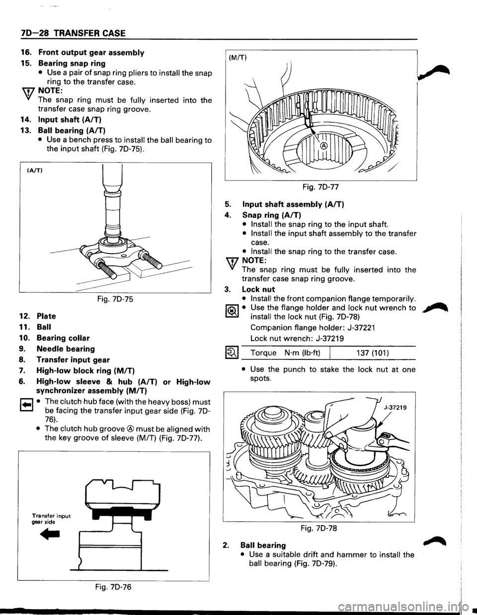
70-28 TRANSFER CASE
16. Front output gear assembly
15. Bearing snap ring
• Use a pair of snap ring pliers to install the snap
ring to the transfer case.
U7NOTE:
VI The snap ring must be fully inserted into the
transfer case snap ring groove.
14. Input shaft (A/T)
13.
Ball bearing (A/T)
• Use a bench press to install the ball bearing to
the
input shaft (Fig. 70-75).
(A/TI
12. Plate
11. Ball
10.
Bearing collar
9. Needle bearing
Fig. 70-75
8. Transfer input gear
7. High-low block ring (MIT)
6. High-low sleeve & hub (A/T) or High-low
synchronizer assembly (MIT)
r=l • The clutch hub face (with the heavy boss) must
1=.1 be facing the transfer input gear side (Fig. 70-
76).
• The clutch hub groove® must be aligned with
the key groove
of sleeve (M/T) (Fig. 70-77).
Transfer input
gear side
Fig. 70-76 Fig.
70-77
5. Input shaft assembly (AIT)
4. Snap ring (A/T)
• Install the snap ring to the input shaft.
• Install the input shaft assembly to the transfer
case.
• lnstal1l the snap ring to the transfer case.
U7 NOTE:
VI The snap ring must be fully inserted into the
transfer case snap ring groove.
3. Lock nut
• Install the front companion flange temporarily.
1®..1• Use the flange holder and lock nut wrench to
install the lock nut (Fig. 70-78)
Companion
flange holder: J-37221
Lock nut wrench: J-37219
1~1 Torque N·m (lb·ft) 137 (101)
2.
• Use the punch to stake the lock nut at one
spots
..
Fig. 70-78
Ball bearing
• Use a suitable drift and hammer to install the
ball bHaring (Fig. 70-79).
•
Page 1213 of 1928
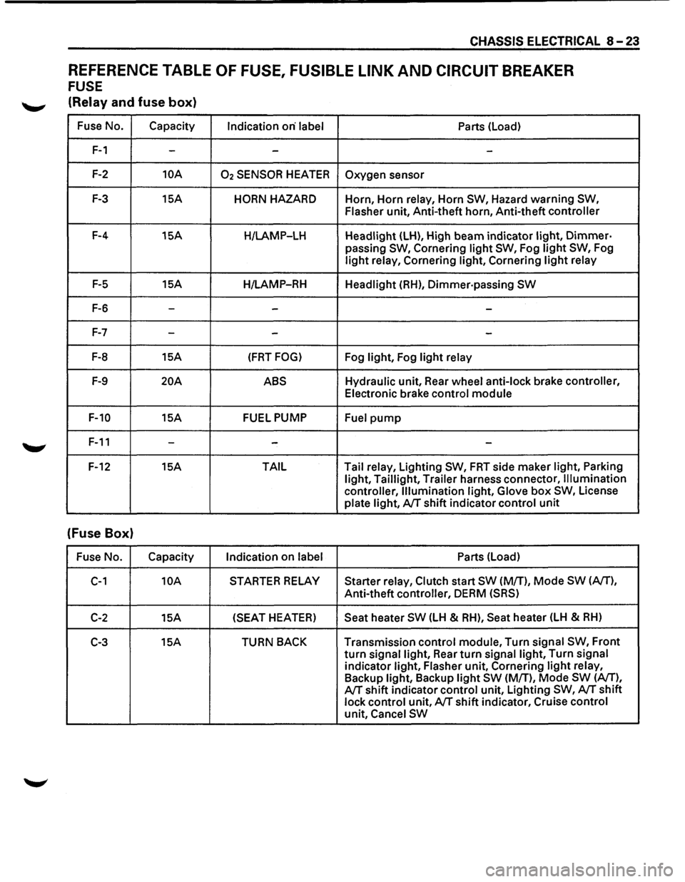
CHASSIS ELECTRICAL 8-23
REFERENCE TABLE OF FUSE, FUSIBLE LINK AND CIRCUIT BREAKER
FUSE
'--"' (Relay and fuse box)
Fuse No. Capacity
Indication on· label Parts (Load)
F-1 --
-
F-2 10A 02 SENSOR HEATER Oxygen sensor
F-3 15A HORN HAZARD Horn, Horn relay, Horn SW, Hazard warning SW,
Flasher
unit, Anti-theft horn, Anti-theft controller
F-4 15A
H/LAMP-LH Headlight (LH), High beam indicator light, Dimmer·
passing SW, Cornering light SW, Fog light SW, Fog
light relay, Cornering light, Cornering light relay
F-5 15A
H/LAMP-RH Headlight (RH), Dimmer·passing SW
F-6 ---
F-7 --
-
F-8 15A (FRT FOG) Fog light, Fog light relay
F-9 20A ABS Hydraulic unit, Rear wheel anti-lock brake controller,
Electronic brake control module
F-10 15A FUEL PUMP
Fuel pump
F-11 ---
F-12 15A TAIL Tail
relay, Lighting SW, FRT side maker light, Parking
light, Taillight, Trailer harness connector, Illumination
controller, Illumination light, Glove
box SW, License
plate light, A/T shift indicator control unit
(Fuse Box)
Fuse No. Capacity
Indication on label Parts (Load)
C-1 10A STARTER RELAY Starter relay, Clutch start SW (M/T), Mode SW (A/T),
Anti-theft controller, DERM (SRS)
C-2 15A (SEAT
HEATER) Seat heater SW (LH & RH), Seat heater (LH & RH)
C-3 15A TURN BACK Transmission control module, Turn signal SW, Front
turn signal light, Rear turn signal light, Turn signal
indicator light, Flasher unit, Cornering light relay,
Backup light, Backup light SW (M/T), Mode SW (A/T),
A/T shift indicator control unit, Lighting SW, A/T shift
lock control unit, A/T shift indicator, Cruise control
unit, Cancel SW
Page 1214 of 1928
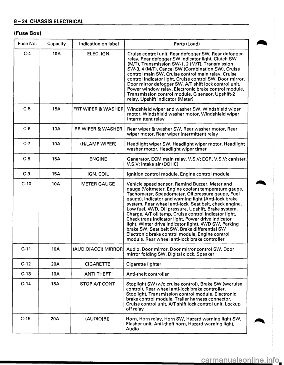
8-24 CHASSIS ELECTRICAL
(Fuse Box)
Fuse No.
Capacity Indication on label Parts (Load)
C-4 10A
ELEC.IGN. Cruise control unit, Rear defogger SW, Rear defogger
relay, Rear
defo9ger SW indicator light, Clutch SW
(M{T), Transmission SW-1, 2 (M!T), Transmission
SW-3, 4 (M{T), Cancel
SW (Combination SW), Cruise
control main
SW, Cruise control main relay, Cruise
control indicator light, Cruise control
SW, Door mirror,
Door mirror defogger SW, AfT shift lock control unit,
Power window relay, Electronic brake control module,
Transmission control module, G sensor, Upshift-2
relay, Upshift indicator (Meter)
C-5 15A FRTWIPER &WASHER
Windshield wipt~r and washer SW, Windshield wiper
motor, Windshit~ld washer motor, Windshield wiper
intermittent relay
C-6 10A RR WIPER & WASHER
Rear wiper & washer SW, Rear washer motor, Rear
wiper motor, Rear wiper intermittent relay
C-7 10A (H/LAMP WIPER) Headlight wiper SW, Headlight wiper motor, Headlight
washer motor, Headlight
wiper timer
C-8 15A ENGINE Generator, ECM main relay, V.S.V; EGA, V.S.V: canister,
V.S.V: intake air
(DOHC)
C-9 15A IGN. COIL Ignition control module, Engine control module
C-10 10A METER GAUGE Vehicle speed stmsor, Remind Buzzer, Meter and
gauge
(Voltmeter, Engine coolant temperature gauge,
Tachometer, Speedometer,
Oil pressure gauge, Fuel
gauge),
Indicator and warning light (Anti-lock brake
system, Rear wheel anti-lock, Seat belt, check engine,
Low fuel, 4WD,
Oil pressure, Upshift, Brake system,
Charge,
AfT oil temp, Cruise control indicator light,
Check trans indicator light,
Power drive indicator
light,
Winter drive indicator light), 4WD SW, Parking
brake SW, Seat belt SW, Brake differential SW
Electronic brake control module, Engine control
module, Rear wheel anti-lock brake controller
C-11 10A (AUDIO[ACCJ) MIRROR Audio, Door mirror, Door mirror control SW, Door
mirror folding SW, Digital clock, Speaker
C-12 20A CIGARETTE Cigarette lighter
C-13 10A
ANTI THEFT Anti-theft controller
C-14 15A
STOP AfT CONT Stoplight SW (w/o cruise control), Brake SW (w/cruise
control), Rear wheel anti-lock brake controller,
Stoplight, Transmission control module, Electronic
brake control module, Trailer harness connector,
Cruise control unit,
AfT shift lock control unit, Lockup
off relay
C-15
20A (AUDIO[B]) Horn,
Horn relay, Horn SW, Hazard warning light SW,
Flasher unit, Anti-theft horn, Hazard warning light,
Audio
•
Page 1215 of 1928
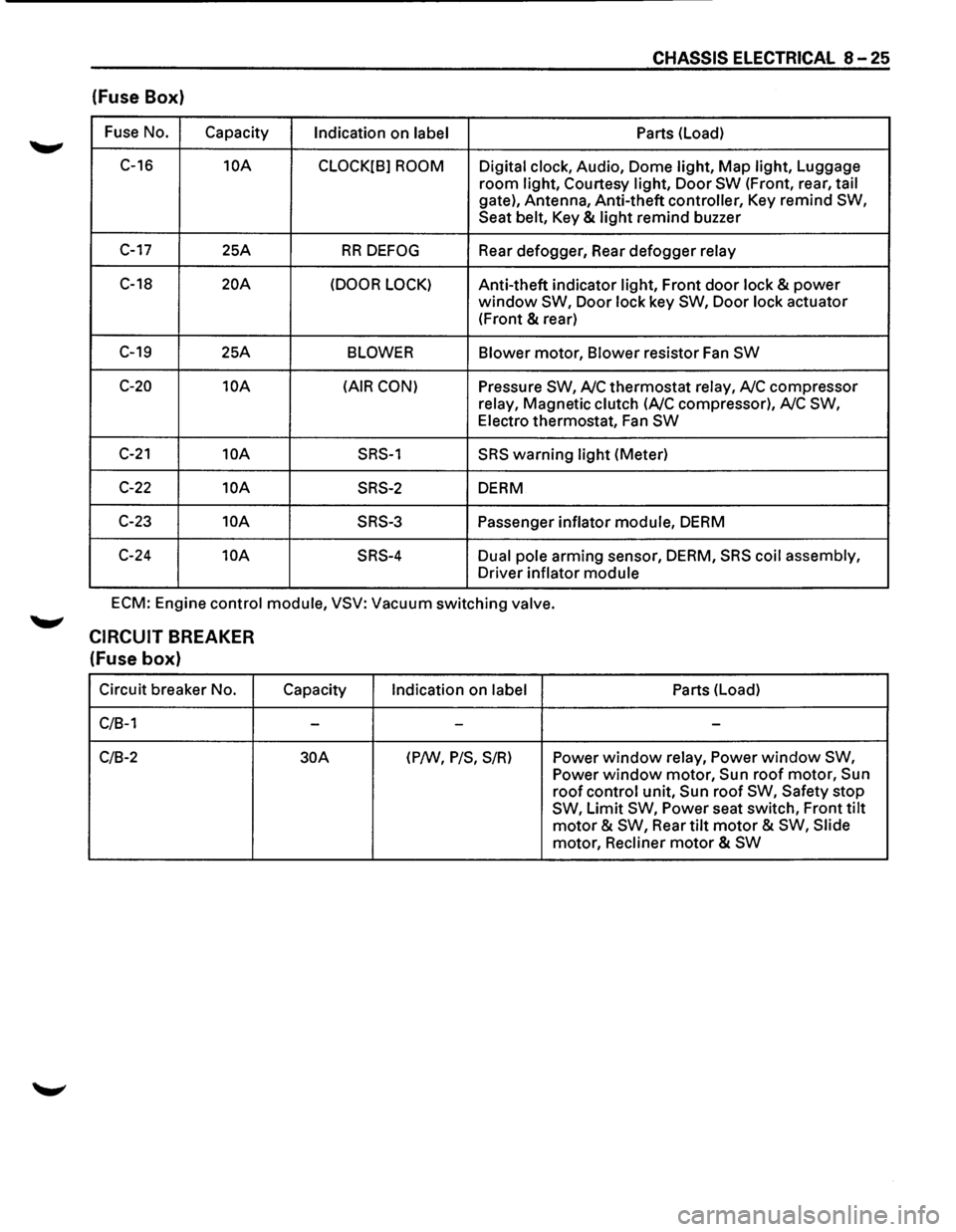
CHASSIS ELECTRICAL 8-25
(fuse Box)
Fuse No.
Capacity Indication on label Parts
(Load)
C-16
10A
CLOCK[B] ROOM Digital clock, Audio, Dome light, Map light, Luggage
room light, Courtesy light, Door SW (Front, rear, tail
gate), Antenna, Anti-theft controller, Key remind SW,
Seat belt, Key & light remind buzzer
C-17 25A RR DEFOG Rear defogger, Rear defogger relay
C-18 20A (DOOR LOCK) Anti-theft indicator light, Front door lock & power
window SW, Door lock key SW, Door lock actuator
(Front
& rear)
C-19 25A BLOWER Blower motor, Blower resistor Fan SW
C-20 10A (AIR CON) Pressure SW, A/C thermostat relay, A/C compressor
relay, Magnetic clutch
(A/C compressor), A/C SW,
Electro thermostat, Fan SW
C-21 10A SRS-1 SRS warning light (Meter)
C-22 10A SRS-2 DERM
C-23
10A SRS-3 Passenger inflator module, DERM
C-24
10A SRS-4 Dual pole arming sensor, DERM, SRS coil assembly,
Driver inflator module
ECM: Engine control module, VSV: Vacuum switching valve.
CIRCUIT BREAKER
(fuse box)
Circuit breaker No.
C/B-1
C/B-2
Capacity
-
30A
Indication on label
-
(P/W, P/S, S/R)
Parts (Load)
-
Power window relay, Power window SW,
Power window motor, Sun roof motor, Sun
roof control unit, Sun roof SW, Safety stop
SW, Limit SW, Power seat switch, Front tilt
motor & SW, Rear tilt motor & SW, Slide
motor, Recliner
motor & SW
Page 1228 of 1928
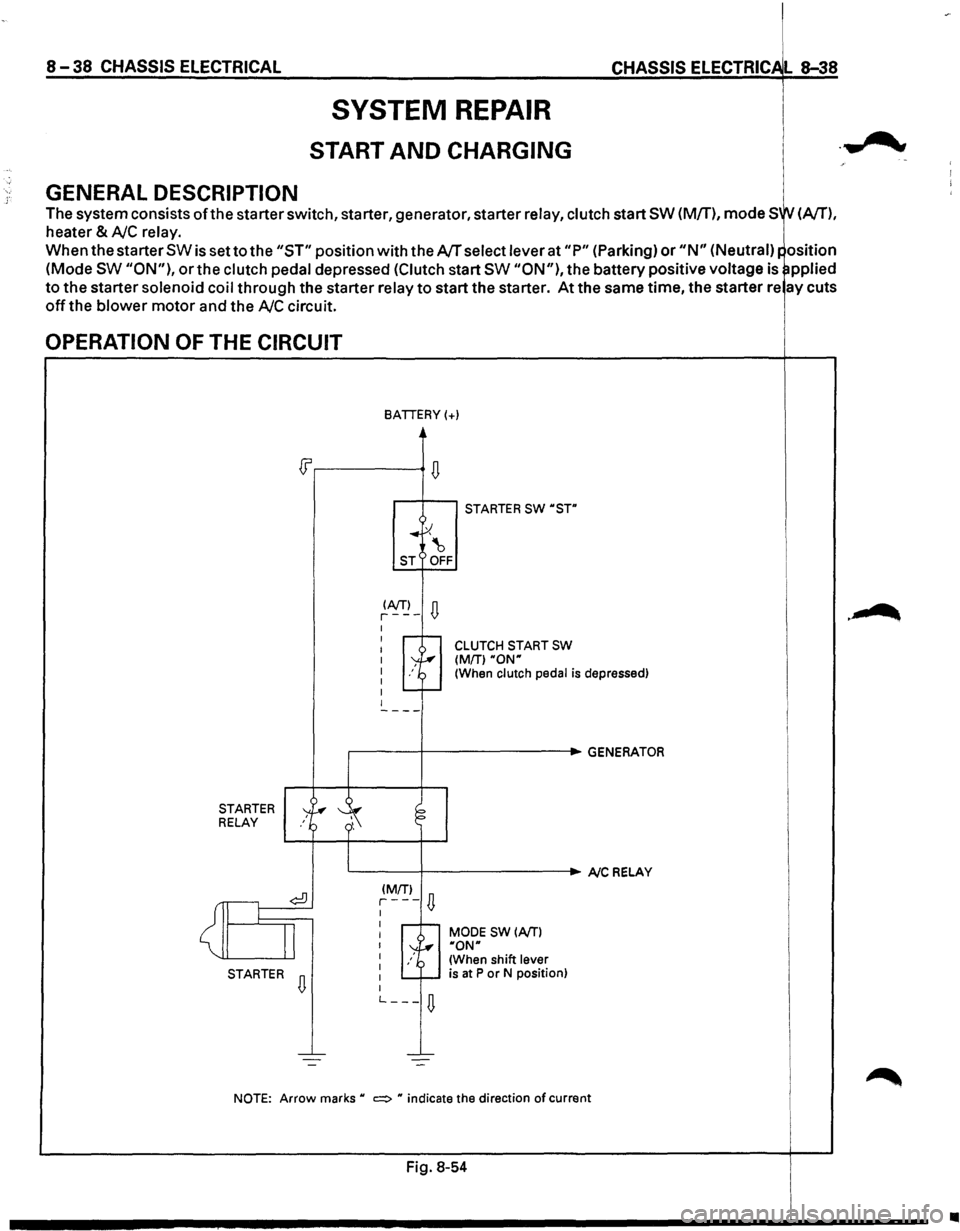
8-38 CHASSIS ELECTRICAL
GENERAL DESCRIPTION
SYSTEM REPAIR
START AND CHARGING
CHASSIS ELECTRIC L 8-38
The system consists ofthe starter switch, starter, generator, starter relay, clutch start SW (M/T), mode SW (A/T),
heater & AJC relay.
When the starter SW is set to the "ST" position with the AJT select lever at "P" (Parking) or "N" (Neutral)~ osition
(Mode SW "ON"), or the clutch pedal depressed (Clutch start SW "ON"), the battery positive voltage is ~pplied
to the starter solenoid coil through the starter relay to start the starter. At the same time, the starter re ay cuts
off the blower motor and the AJC circuit.
OPERATION OF THE CIRCUIT
STARTER RELAY
<~
STARTER
BATTERY(+)
~ .. ~ ~ ST OFF
~A!fJ-D I I -r-1 I I I I I
STARTER SW ·sTn
CLUTCH START SW (MfTl ·ow (When clutch pedal is depressed)
,-------+----------.GENERATOR
~ ';
L.-----+----------. A/C RELAY
¢!) (MrrJ
D r---I
I
I r--r-MODE SW (A/T) I ~ I y, ·oNn I /~ (When shift lever I is at P or N position)
D I -r-I L ___
D
NOTE: Arrow marks • c:::::> • indicate the direction of current
Fig. 8-54
•
Page 1229 of 1928
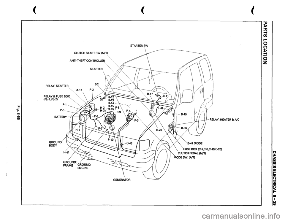
, cCi" 00 I (11
(11
(
CLUTCH
START
SW
(M/Tl
ANTI-THEFT
CONTROLLER
STARTER
RELAY:
STARTER
" ~-
X-17
P-2
-, '
RELAY
& FUSE
BOX
(FL-1,
FL-2)
""" "'
P-1
'
----------
... / ,.,
BATTERY
If
I
GROUND: BODY
/ H-41
,_
(
STARTERSW
( RELAY:
HEATER
&AIC
FUSE
BOX
(C-1,C-8,C-19,C-20)
CLUTCH
PEDAL
(M{T)
MODE
SW.
(A/11
(
~ ::lJ -1 CJ) r-0 (") ~ 0 2
n ::1: ~ (I) en m rm ~ n )> r-eo I (A) CD
Page 1230 of 1928
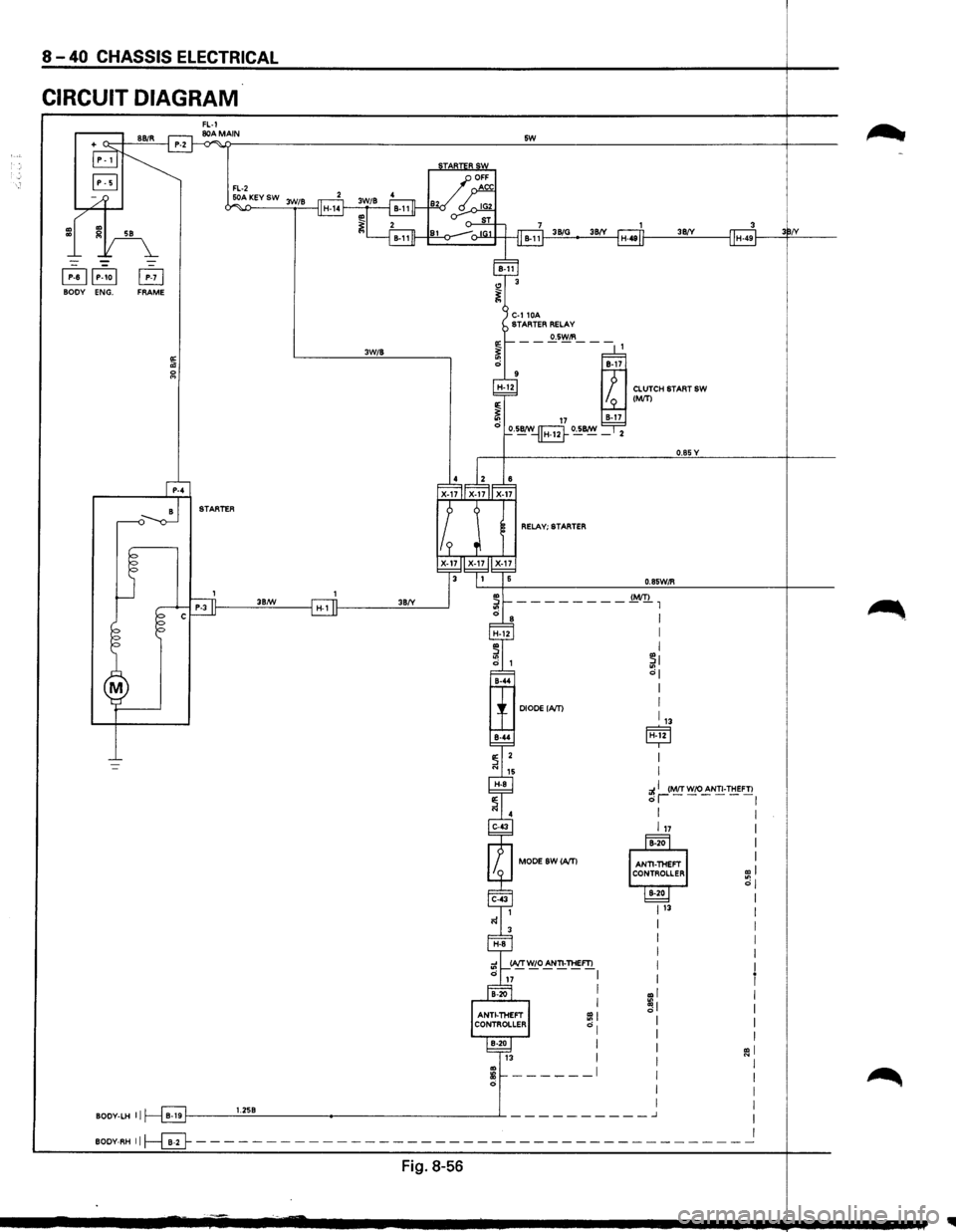
8 -40 CHASSIS ELECTRICAL
CIRCUIT DIAGRAM
B BOOY ENG. FRAME
3W/B
~--.:!3~BNI!!..__~ H-1 38/Y
sw
--J:.S'!!ffl_ -~-1 B-17
17 B-17 0 SB/W rr.:;-;:;1 O.SB/W -~---2
38{V
CLUTCH START SW (M/T)
O.BSY
O.BSW!R (M/T) ----------1
iRI 01
I
I
______ I I
I
I 31 ~I
I I
113
Hz I
I I
u~lrc~~~N.!!:T..':I!r:.!! o I I
I I 11 I
I
I
ml ~I
I 113 I
I I I I
I I
: j .,1 I ~I I I I I I
I ~I I I
I I
I I I I BOOY-LHll B-19 1.2SB __________ ...J I
I
BODY·RH II~----------------------------------------
Fig. 8-56
~-
Page 1234 of 1928
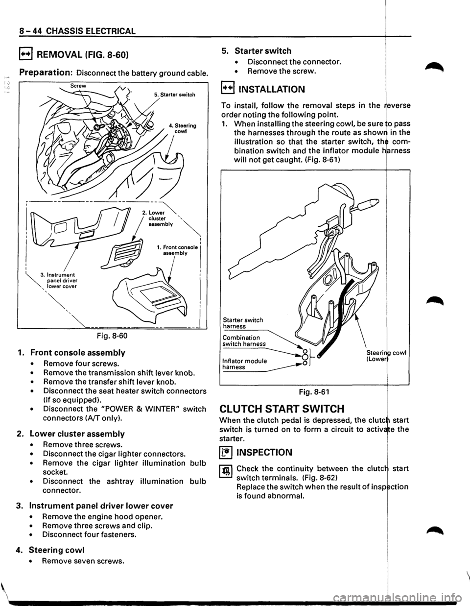
8-44 CHASSIS ELECTRICAL
B REMOVAL (FIG. 8-60)
Preparation: Disconnect the battery ground cable.
5. Starter switch
Fig. 8-60
1. Front console assembly
• Remove four screws.
• Remove the transmission shift lever knob.
• Remove the transfer shift lever knob.
• Disconnect the seat heater switch connectors
(If so equipped).
• Disconnect the "POWER & WINTER" switch
connectors
(A/T only).
2. Lower cluster assembly
• Remove three screws.
• Disconnect the cigar lighter connectors.
• Remove the cigar lighter illumination bulb
socket.
• Disconnect the ashtray illumination bulb
connector.
3. Instrument panel driver lower cover
• Remove the engine hood opener.
• Remove three screws and clip.
• Disconnect four fasteners.
4. Steering cowl
• Remove seven screws .
5. Starter switch
• Disconnect the connector.
• Remove the screw.
B INSTALLATION
To install, follow the removal steps in the everse
order noting the
following point.
1. When installing the steering cowl, be sure o pass
the harnesses through the route as
show in the
illustration so that the starter switch, th com
bination switch and the inflator
module
will not get caught. (Fig. 8-61)
Starter switch
harness
Fig. 8-61
CLUTCH START SWITCH
cowl
When the clutch pedal is depressed, the clute start
switch is turned on
to form a circuit to activ e the
starter.
~ INSPECTION
1 til!. I Check the continuity between the clute start
switch terminals. (Fig. 8-62)
Replace the switch when the result
of insp ction
is found abnormal.
'
Page 1235 of 1928
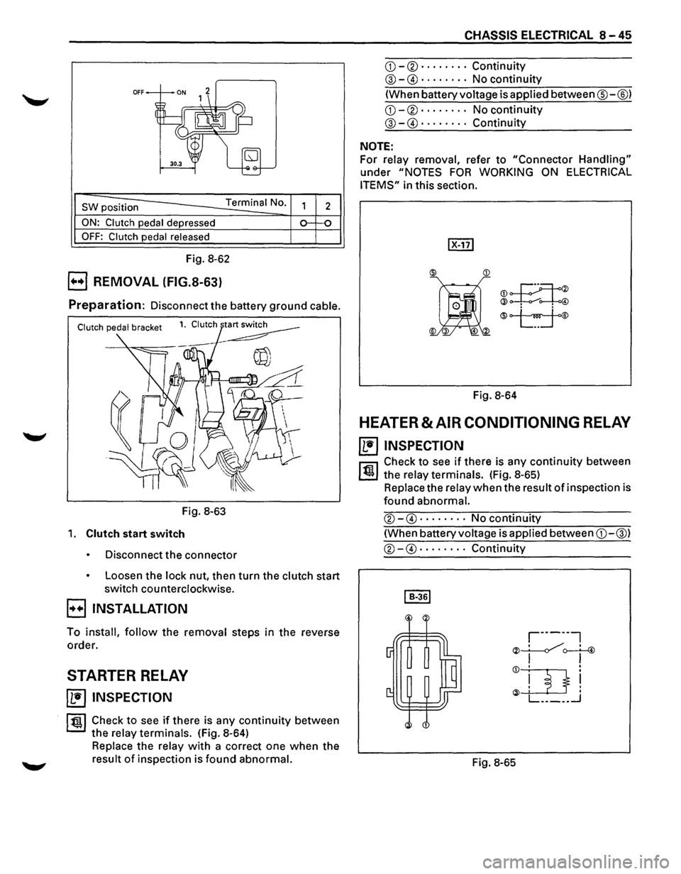
OFF
SW position Terminal No.
ON: Clutch pedal depressed
OFF: Clutch pedal released
Fig. 8-62
B REMOVAL (FIG.S-63)
2
Preparation: Disconnect the battery ground cable.
Fig. 8-63
1. Clutch start switch
Disconnect the connector
Loosen the lock nut, then turn the clutch start
switch counterclockwise.
B INSTALLATION
To install, follow the removal steps in the reverse
order.
STARTER RELAY
~ INSPECTION
ltgl Check to see if there is any continuity between
the relay terminals. (Fig. 8-64)
Replace the relay with a correct one when the
result of inspection is found abnormal.
CHASSIS ELECTRICAL 8-45
CD-®······ · · Continuity
@-G)· . · · · · .. No continuity
(When battery voltage is applied between®-@)
CD-®· · · · · · · · No continuity
@-G)· · · · · · · · Continuity
NOTE:
For relay removal, refer to "Connector Handling"
under "NOTES FOR WORKING ON ELECTRICAL
ITEMS"
in this section.
®JI
@~
®
Fig. 8-64
HEATER & AIR CONDITIONING RELAY
~ INSPECTION
l'fll Check to see if there is any continuity between
~ the relay terminals. (Fig. 8-65)
Replace the relay when the result of inspection is
found abnormal.
®-G) ..... · .. No continuity
(When battery voltage is applied between CD-@)
®-G) .... · · .. Continuity
Fig. 8-65
Page 1237 of 1928
CHASSIS ELECTRICAL 8-47
ENGINE CONTROL MODULE (ECM)
GENERAL DESCRIPTION
The ECM is used to control the fuel system of the
vehicle, especially in controlling the following items.
1. FUEL CONTROL
The amount of fuel and air sent into the combus
tion chamber is controlled by controlling the fuel
sent through the injector.
2. ELECTRIC FUEL PUMP (INSTALLED IN
THE FUEL TANK)
The in-tank fuel pump is controlled by the ECM.
When starter switch is turned on, the pump will
run for 2 seconds, then stop unless the engine is
cranking
or running.
3. IGNITION CONTROL
The system is controlled by the spark timing con
trol function of the ECM.
4. CIRCULATION OF EXHAUST GAS
The system controls the formation of NOx by
returning a small amount of exhaust gas to the
intake manifold
through the control valve.
'-" lAC: Idle air control
5. CONTROL OF AIR CONDITIONING (A/C)
For improved engine idling performance, the sys
tem controls the operation of the air conditioner
by regulating the
clutch operation ofthe A/C com
pressor in accordance
with changes in operation.
6. IDLE AIR CONTROL
The system controls the lAC Valve for the desired
idle speed in accordance
with changes in
operation.
7. DIAGNOSIS OF TROUBLES
When a sensor detects any signal that the ECM is
in
an abnormal condition, the ECM turns on the
malfunction
indicator (CHECK ENGINE) light in
the meter, and stores at the same
time the corre
sponding diagnostic
trouble code (DTC) in the
memory to indicate to which system or circuit the
trouble represented by the
DTC belongs.
The ECM inspection connector (data link connec
tor) is used
to retrieve the DTCs stored from the
ECM.
Refer to Section 6 "ENGINE DIAGNOSIS" for de
tails.