clutch ISUZU TROOPER 1995 Workshop Manual
[x] Cancel search | Manufacturer: ISUZU, Model Year: 1995, Model line: TROOPER, Model: ISUZU TROOPER 1995Pages: 1928
Page 1154 of 1928
7C-20 CLUTCH
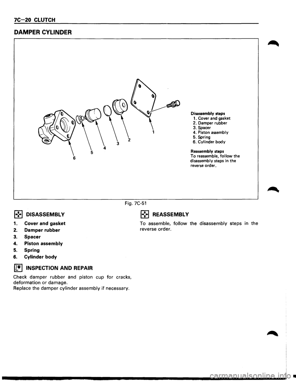
DAMPER CYLINDER
6
(®)
2 1
Disassembly steps
1. Cover and gasket
2. Damper rubber
3. Spacer 4. Piston assembly 5. Spring
6. Cylinder body
Reassembly steps To reassemble, follow the disassembly steps in the
reverse order.
Fig. 7C-51
l .. !•l DISASSEMBL V
1. Cover and gasket
2. Damper rubber
3. Spacer
4. Piston
assembly
5. Spring
6. Cylinder body
IL•I INSPECTION AND REPAIR
Check damper rubber and piston cup for cracks,
deformation
or damage.
Replace the damper cylinder assembly if necessary.
1•! .. 1 REASSEMBL V
To assemblo, follow the disassembly steps in the
reverse order.
•
Page 1155 of 1928
CLUTCH 7C-21
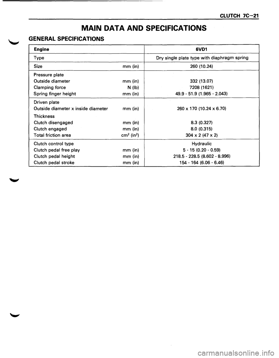
MAIN DATA AND SPECIFICATIONS
GENERAL SPECIFICATIONS
Engine 6VD1
Type Dry single plate type with diaphragm spring
Size mm (in) 260 (10.24)
Pressure plate
Outside
diameter mm (in) 332 (13.07)
Clamping force N (lb) 7208 (1621)
Spring finger height mm (in) 49.9 -51.9 (1.965 -2.043)
Driven plate
Outside
diameter x inside diameter mm (in) 260 X 170 (10.24 X 6.70)
Thickness
Clutch disengaged mm (in) 8.3 (0.327)
Clutch engaged mm (in) 8.0 (0.315)
Total friction area cm2 (in2
) 304 X 2 (47 X 2)
Clutch control type Hydraulic
Clutch pedal
free play mm (in) 5 -15 (0.20 -0.59)
Clutch pedal height mm (in) 218.5 -228.5 (8.602 -8.996)
Clutch pedal stroke mm (in) 154 -164 (6.06 -6.46)
Page 1156 of 1928
![ISUZU TROOPER 1995 Workshop Manual 7C-22 CLUTCH
TORQUE SPECIFICATIONS N·m (lb·ft)
76(56)]
Fig. 7C-52
•](/img/61/57183/w960_57183-1155.png "ISUZU TROOPER 1995 Workshop Manual 7C-22 CLUTCH
TORQUE SPECIFICATIONS N·m (lb·ft)
76(56)]
Fig. 7C-52
•")
7C-22 CLUTCH
TORQUE SPECIFICATIONS N·m (lb·ft)
76(56)]
Fig. 7C-52
•
Page 1157 of 1928
CLUTCH 7C-23
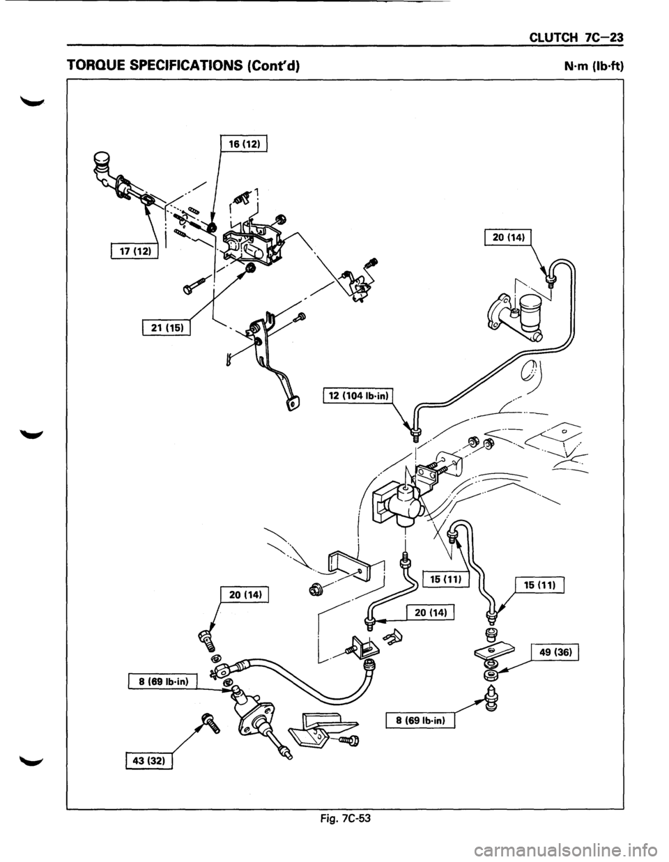
TORQUE SPECIFICATIONS (Cont'd) N·m (lb·ft)
16 (12)
12
(104 lb·in)
8 (691b·in)
8 (691b·in)
Fig. 7C-53
Page 1158 of 1928
7C-24 CLUTCH
ILLUSTRATION
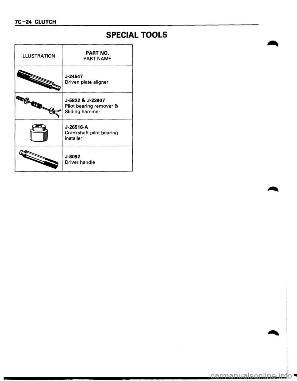
SPECIAL TOOLS
PART NO.
PART NAME
J-24547 Driven
plate aligner
J-5822 & J-23907
Pilot bearing remover &
Sliding hammer
J-26516-A Crankshaft
pilot bearing
installer
J-8092
Driver handle
•
Page 1175 of 1928
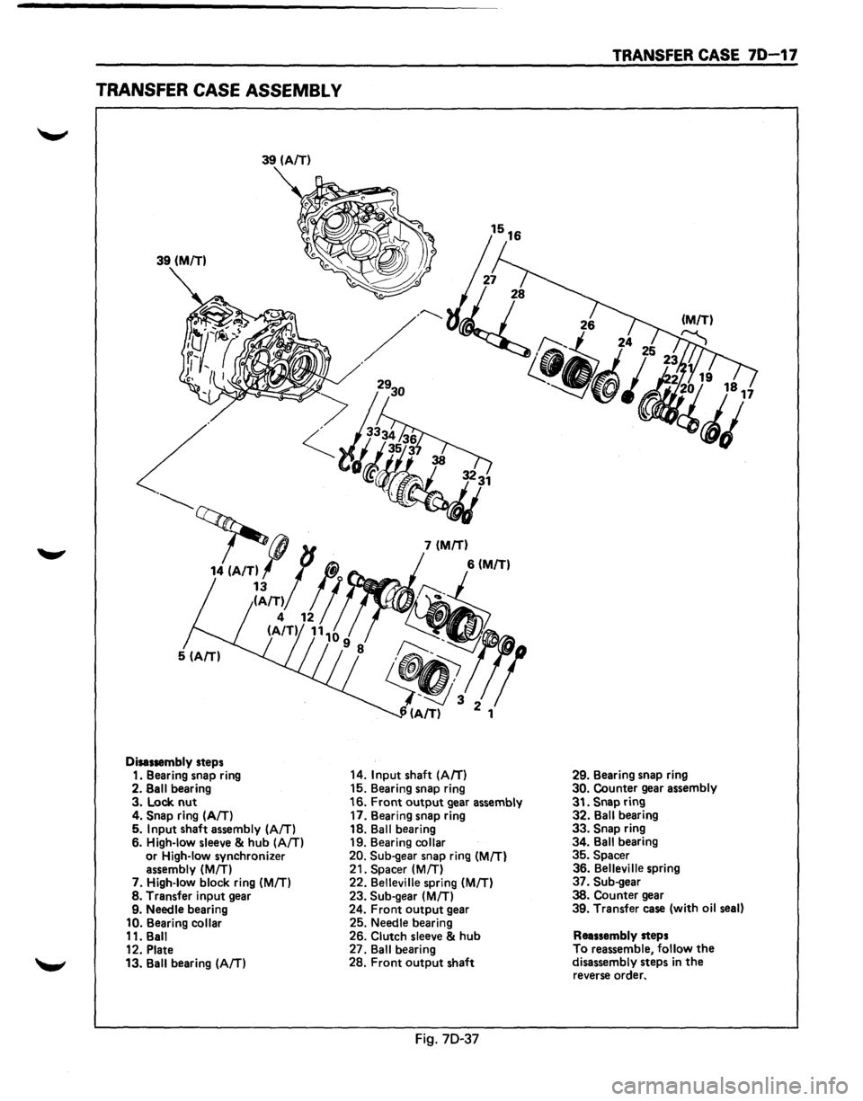
TRANSFER CASE ASSEMBL V
39 (AfT)
39
(MIT)
Disassembly steps
1. Bearing snap ring
2.
Sail bearing 3. Lock nut 4. Snap ring (AIT) 5. Input shaft assembly (AIT) 6. High-low sleeve & hub (AIT) or High-low synchronizer
assembly (MIT) 7. High-low block ring (MIT) 8. Transfer input gear
9. Needle bearing
10. Bearing collar 11. Ball
12. Plate
13. Ball bearing
(AIT)
14. Input shaft (A/T)
15. Bearing snap ring
16.
Front output gear assembly
17. Bearing snap ring
18.
Ball bearing
19. Bearing collar
20. Sub-gear snap ring (MIT) 21. Spacer (M/T)
22. Belleville spring (MIT) 23. Sub-gear (MIT) 24. Front output gear
25. Needle bearing
26.
Clutch sleeve & hub 27. Ball bearing
28. Front output shaft
Fig. 70-37
TRANSFER CASE 7D-17
29. Bearing snap ring 30. Counter gear assembly
31.
Snap ring 32. Ball bearing 33. Snap ring
34. Ball bearing
35. Spacer 36. Belleville spring
37. Sub-gear
38. Counter gear 39. Transfer case (with oil seal)
Reassembly steps
To reassemble,
follow the disassembly steps in the reverse order.
Page 1177 of 1928
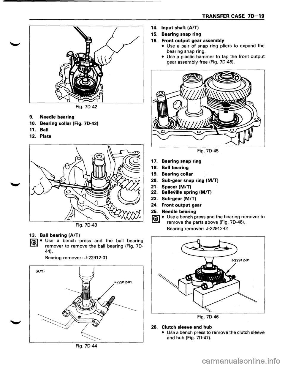
Fig. 70-42
9. Needle bearing
10. Bearing collar (Fig. 70-43)
11. Ball
12. Plate
Fig. 70-43
13. Ball bearing (AIT)
li0\1 • Use a bench press and the ball bearing
I.S!il remover to remove the ball bearing (Fig. 70-
44).
Bearing remover: J-22912-01
(AfT)
J-22912·01
Fig. 70-44
TRANSFER CASE 70-19
14. Input shaft (AIT)
15. Bearing snap ring
16.
Front output gear assembly
• Use a pair of snap ring pliers to expand the
bearing snap ring.
• Use a plastic hammer to tap the front output
gear assembly free (Fig. 70-45).
Fig. 70-45
17. Bearing snap ring
18.
Ball bearing
19. Bearing
collar
20. Sub-gear snap ring (MIT)
21. Spacer (MIT)
22. Belleville spring (MIT)
23. Sub-gear (MIT)
24. Front output gear
25. Needle bearing
li0\1 • Use a bench press and the bearing remover to
I.S!il remove the parts above (Fig. 70-46).
Bearing remover: J-22912-01
Fig.
70-46
26. Clutch sleeve and hub
• Use a bench press to remove the clutch sleeve
and hub (Fig.
70-47).
Page 1179 of 1928
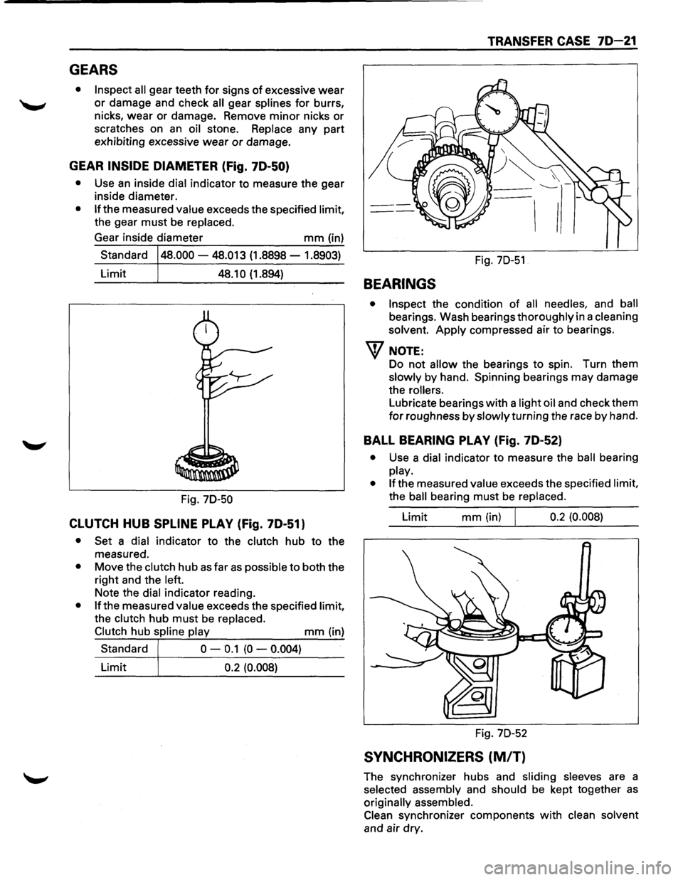
GEARS
• Inspect all gear teeth for signs of excessive wear
'--" or damage and check all gear splines for burrs,
nicks,
wear or damage. Remove minor nicks or
scratches on an oil stone. Replace any part
exhibiting excessive wear or damage.
GEAR INSIDE DIAMETER (Fig. 7D-50}
• Use an inside dial indicator to measure the gear
inside diameter.
• If the measured value exceeds the specified limit,
the gear
must be replaced.
Gear inside diameter
mm (in)
Standard
48.000 -48.013 (1.8898 -1.8903)
Limit 48.1 0 (1.894)
Fig.
70-50
CLUTCH HUB SPLINE PLAY (Fig. 7D-51)
• Set a dial indicator to the clutch hub to the
measured.
• Move the clutch hub as far as possible to both the
right and the left.
Note the dial indicator reading.
• If the measured value exceeds the specified limit,
the clutch hub
must be replaced.
Clutch hub spline play
mm (in)
Standard
0 -0.1 (0 -0.004)
Limit 0.2 (0.008)
TRANSFER CASE 7D-21
I I
Fig. 70-51
BEARINGS
• Inspect the condition of all needles, and ball
bearings. Wash bearings thoroughly in a cleaning
solvent.
Apply compressed air to bearings.
W NOTE:
Do not allow the bearings to spin. Turn them
slowly by hand. Spinning bearings may damage
the
rollers.
Lubricate bearings with a light oil and check them
for roughness by slowly turning the race by hand.
BALL BEARING PLAY (Fig. 7D-52}
• Use a dial indicator to measure the ball bearing
play.
• If the measured value exceeds the specified limit,
the
ball bearing must be replaced.
Limit
mm (in) I 0.2 (0.008)
Fig. 70-52
SYNCHRONIZERS (MIT)
The synchronizer hubs and sliding sleeves are a
selected assembly and should be kept together
as
originally assembled.
Clean synchronizer components
with clean solvent
and air dry.
Page 1180 of 1928
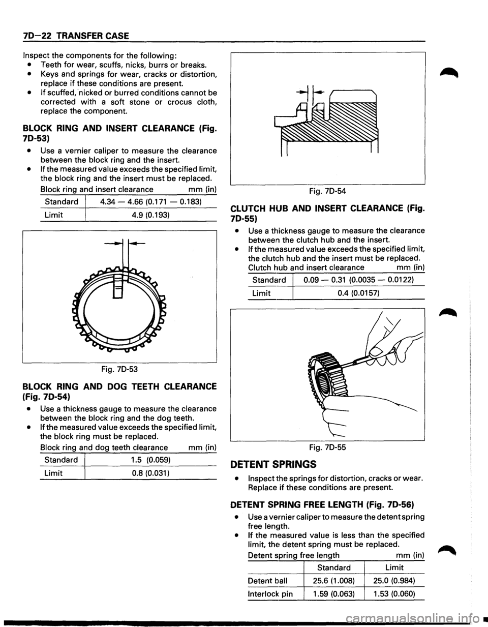
7D-22 TRANSFER CASE
Inspect the components for the following:
• Teeth for wear, scuffs, nicks, burrs or breaks.
• Keys and springs for wear, cracks or distortion,
replace
if these conditions are present.
• If scuffed, 'nicked or burred conditions cannot be
corrected with a soft stone or crocus cloth,
replace the component.
BLOCK RING AND INSERT CLEARANCE (Fig.
7D-53)
• Use a vernier caliper to measure the clearance
between the block ring and the insert.
• If the measured value exceeds the specified limit,
the block ring and the insert
must be replaced.
Block ring and insert clearance
mm (in)
Standard
4.34-4.66 (0.171 - 0.183)
Limit 4.9 (0.193)
Fig. 7D-53
BLOCK RING AND DOG TEETH CLEARANCE
(Fig. 7D-54)
• Use a thickness gauge to measure the clearance
between the block ring and the dog teeth.
• If the measured value exceeds the specified limit,
the block ring
must be replaced. Fig.
7D-54
CLUTCH HUB AND INSERT CLEARANCE (Fig.
7D-55)
• Use a thickness gauge to measure the clearance
between the clutch hub and the insert.
• If the measured value exceeds the specified limit,
the
clutch hub and the insert must be replaced.
Clutch hub and insert clearance
mm (in)
Standard 0.09 -
0.31 (0.0035 -0.0122)
Limit 0.4 (0.0157)
Block ring and dog teeth clearance
mm (in) Fig. 7D-55 ------~~--~------------------~ Standard 1.5 (0.059)
Limit 0.8
(0.031) DETENT SPRINGS
• Inspect the springs for distortion, cracks or wear.
Replace
if these conditions are present.
DETENT SPRING FREE LENGTH (Fig. 7D-56)
• Use a vernier caliper to measure the detent spring
free length.
• If the measured value is less than the specified
limit, the detent spring
must be replaced.
Detent spring free length
mm (in)
Standard Limit
Detent ball 25.6
(1.008) 25.0 (0.984)
Interlock pin 1.59 (0.063) 1.53
(0.060)
•
Page 1184 of 1928
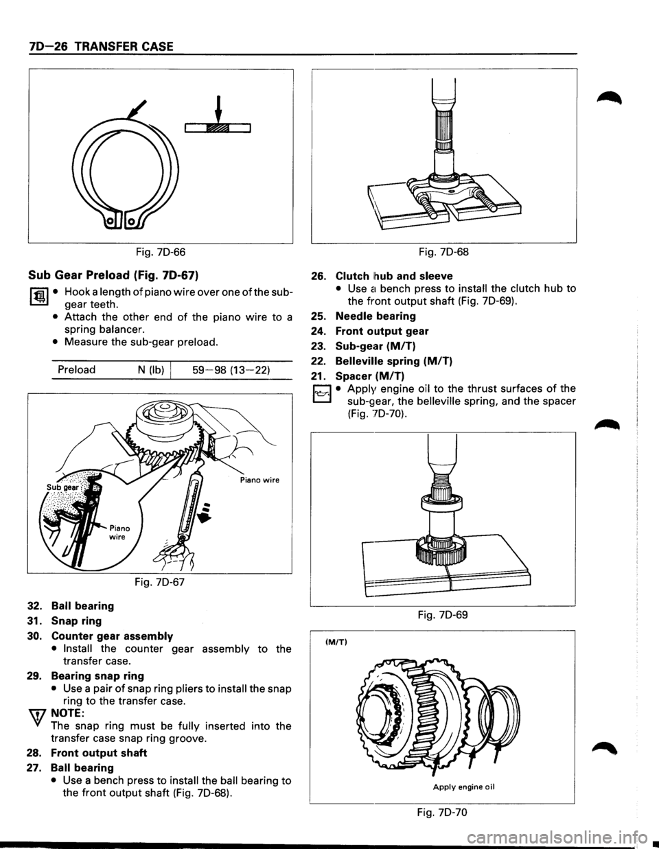
70-26 TRANSFER CASE
Fig. 70-66
Sub Gear Preload (Fig. 70-67)
~·
Hook a length of piano wire over one of the sub
gear teeth.
• Attach the other end of the piano wire to a
spring
balancer.
•
Measure the sub-gear preload.
Preload
32. Ball bearing
31.
Snap ring
N (lb)
Fig. 70-67
30. Counter gear assembly
59-98 (13-22)
• Install the counter gear assembly to the
transfer case.
29. Bearing snap ring
• Use a pair of snap ring pliers to install the snap
ring
to the transfer case.
W NOTE:
~ The snap ring must be fully inserted into the
transfer case snap ring groove.
28. Front output shaft
27. Ball bearing
• Use a bench press to install the ball bearing to
the front output shaft (Fig. 70-68).
Fig. 70-68
26. Clutch hub and sleeve
• Use a bench press to install the clutch hub to
the front output shaft (Fig. 70-69).
25. Needle bearing
24.
Front output gear
23. Sub-gear
(MIT)
22. Belleville spring (MIT)
21. Spacer (M/T)
C1 • Apply engine oil to the thrust surfaces of the
t.::::::J sub-gear, the belleville spring, and the spacer
(Fig.
70-70).
Fig. 70-69
(M/TI
Apply engine oil
Fig. 70-70
•