clutch ISUZU TROOPER 1995 Workshop Manual
[x] Cancel search | Manufacturer: ISUZU, Model Year: 1995, Model line: TROOPER, Model: ISUZU TROOPER 1995Pages: 1928
Page 1144 of 1928
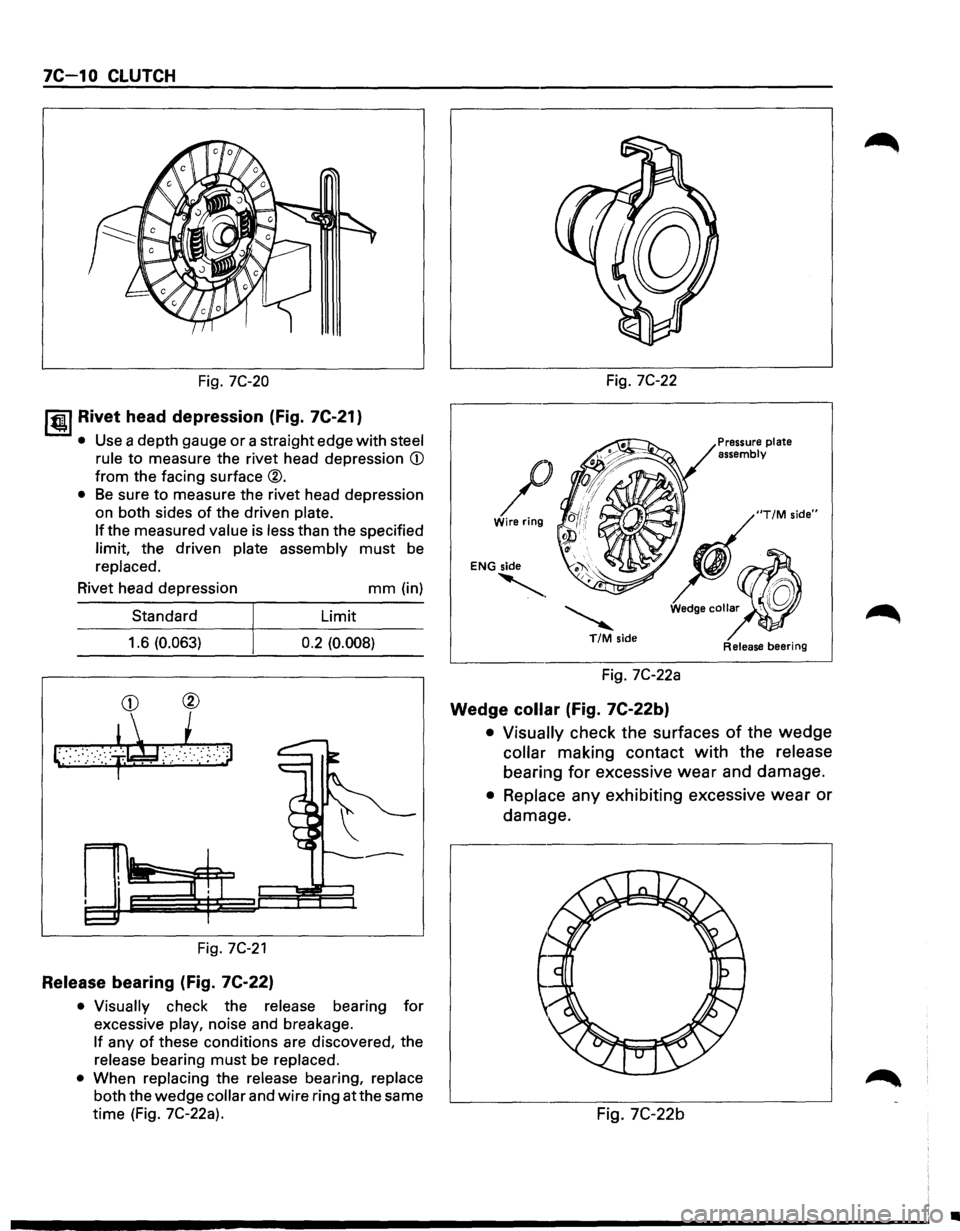
7C-1 0 CLUTCH
Fig. 7C-20
I til!. I Rivet head depression (Fig. 7C-21}
• Use a depth gauge or a straight edge with steel
rule
to measure the rivet head depression CD
from the facing surface ®.
• Be sure to measure the rivet head depression
on both sides
of the driven plate.
If the measured value is less than the specified
limit, the driven plate assembly must be
replaced.
Rivet head depression
Standard
1.6
(0.063)
CD ®
~··· ·$~,i ') ; :. : .: ::,:. . ~· ,• · . .' : ·.· :· .. , .
Fig. 7C-21
Release bearing (Fig. 7C-22}
mm (in)
Limit
0.2 (0.008)
• Visually
check the release bearing for
excessive play, noise and breakage.
If any of these conditions are discovered, the
release bearing must be replaced.
•
When replacing the release bearing, replace
both the wedge collar and wire ring at the same
time (Fig. 7C-22a). Fig.
7C-22
/ Wire
ring
ENG side
'· ~ T/M side
Fig. 7C-22a
Wedge collar (Fig. 7C-22b}
Pressure plate
assembly
Release bearing
• Visually check the surfaces of the wedge
collar making contact with the release
bearing for excessive wear and damage.
• Replace any exhibiting excessive wear or
damage.
Fig.
7C-22b
•
Page 1145 of 1928
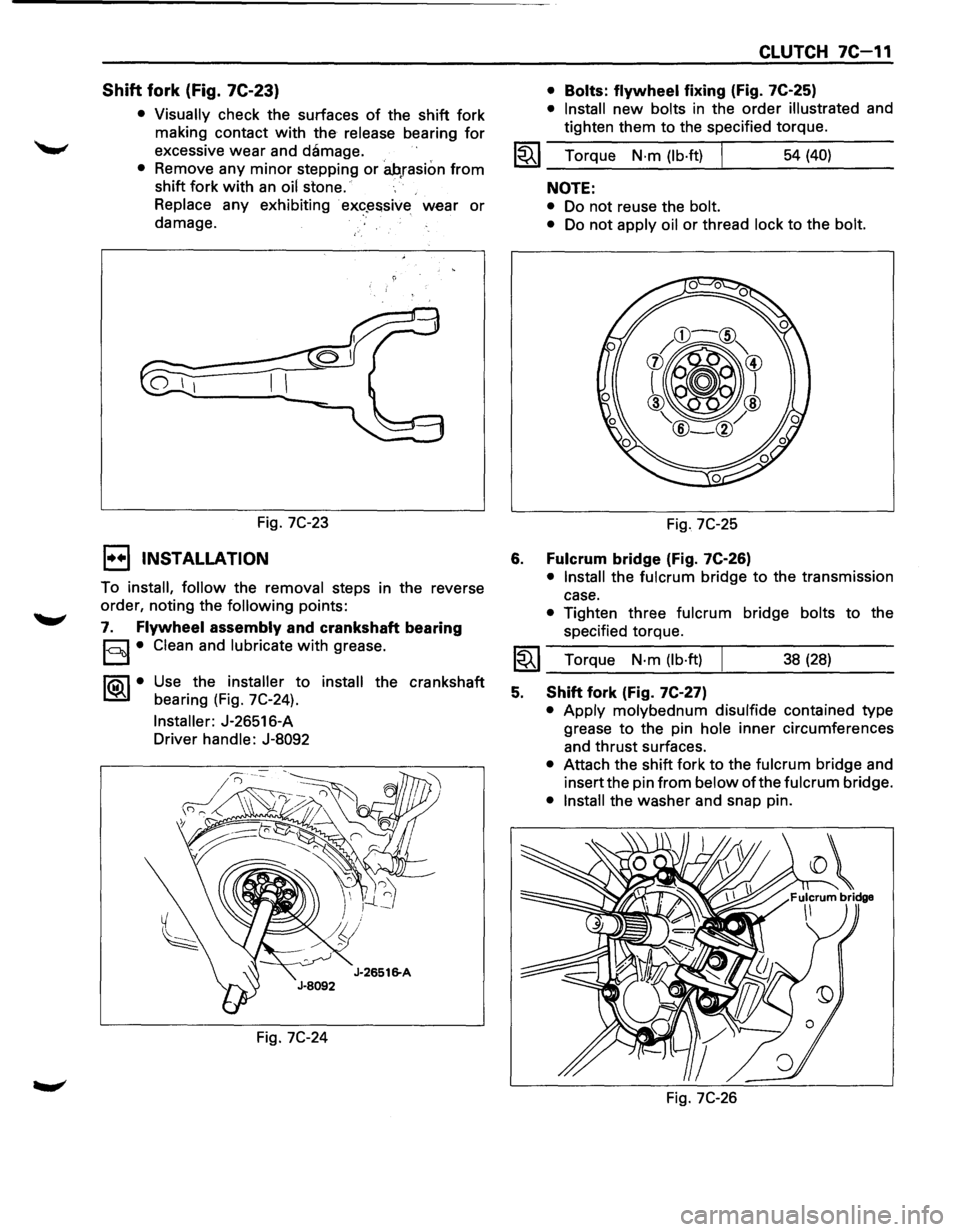
Shift fork (Fig. 7C-23)
• Visually check the surfaces of the shift fork
making contact
with the release bearing for
excessive wear and damage.
• Remove any minor stepping or ah,rasion from
shift fork with an oil stone.
Replace any exhibiting
· ex«?~ssive wear or
damage.
Fig.
7C-23
1••1 INSTALLATION
To install, follow the removal steps in the reverse
order, noting the
following points:
7. Flywheel assembly and crankshaft bearing
§I• Clean and lubricate with grease.
1®..1• Use the installer to install the crankshaft
bearing (Fig. 7C-24).
Installer: J-26516-A
Driver handle: J-8092
Fig.
7C-24
CLUTCH 7C-11
• Bolts: flywheel fixing (Fig. 7C-25)
• Install new bolts in the order illustrated and
tighten them to the specified torque.
1~1 Torque N·m (lb·ft) I 54 (40)
6.
NOTE:
• Do not reuse the bolt.
•
Do not apply oil or thread lock to the bolt.
Fig. 7C-25
Fulcrum bridge (Fig. 7C-26)
• Install the fulcrum bridge to the transmission
case.
• Tighten three fulcrum bridge bolts to the
specified torque.
I~I __ T_o_rq~u_e __ N_·_m~(_lb_·ft_l~ _____ 3_8_(_28_) ____ _
5. Shift fork (Fig. 7C-27)
• Apply molybednum disulfide contained type
grease
to the pin hole inner circumferences
and thrust surfaces.
• Attach the shift fork to the fulcrum bridge and
insert the pin
from below of the fulcrum bridge.
• Install the washer and snap pin.
Fig.
7C-26
Page 1146 of 1928
7C-12 CLUTCH
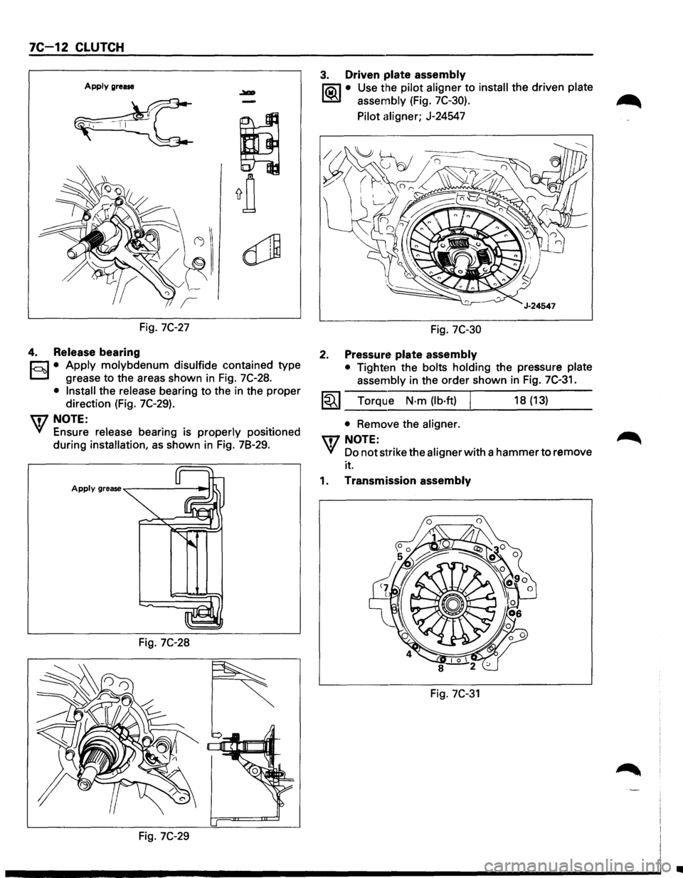
Apply grease
Fig. 7C-27
4. Release bearing
r;:J • Apply molybdenum disulfide contained type
D grease to the areas shown in Fig. 7C-28.
• Install the release bearing to the in the proper
direction (Fig.
7C-29).
U7 NOTE:
VI Ensure release bearing is properly positioned
during
installation, as shown in Fig. 78-29.
Fig. 7C-28
Fig. 7C-29
3. Driven plate assembly
liQ\1 • Use the pilot aligner to install the driven plate
~ assembly (Fig. 7C-30).
Pilot aligner; J-24547
Fig. 7C-30
2. Pressure plate assembly
• Tighten the bolts holding the pressure plate
assembly in the order shown in
Fig. 7C-31.
1~1 Torque N·m (lb·ft) I 18 (13)
• Remove the aligner.
UJNOTE:
VI Do not strike the aligner with a hammer to remove
it.
1. Transmission assembly
Fig. 7C-31
•
Page 1147 of 1928
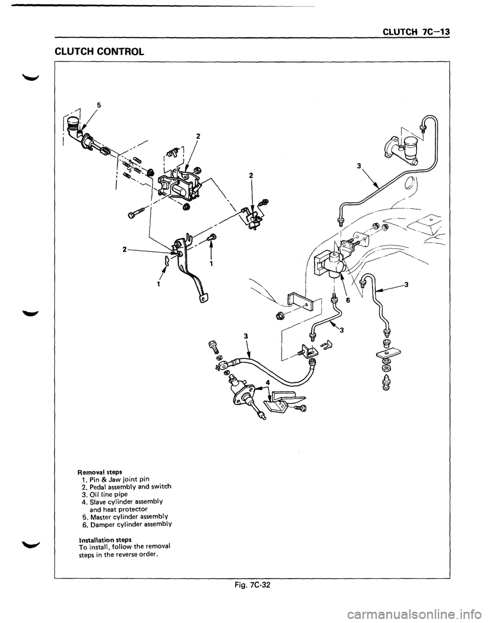
CLUTCH CONTROL
5
Removal steps
1. Pin & Jaw joint pin
2. Pedal assembly and switch
3.
Oil line pipe
4. Slave cylinder assembly
and heat protector
5. Master cylinder assembly
6. Damper cylinder assembly
Installation steps
To install, follow the removal
steps
in the reverse order.
CLUTCH 7C 13
Fig. 7C-32
Page 1148 of 1928
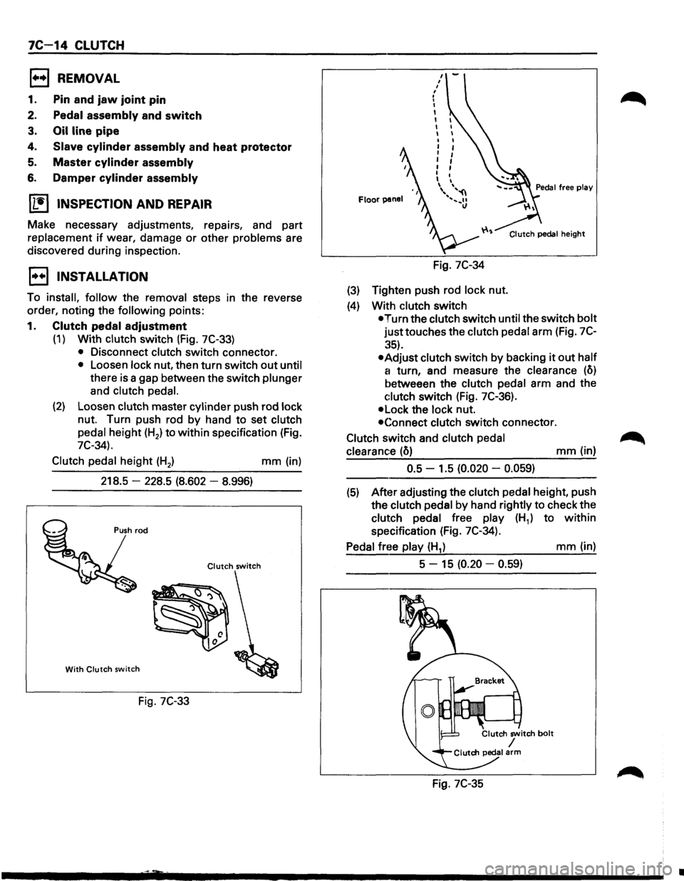
7C 14 CLUTCH
1••1 REMOVAL
1. Pin and jaw joint pin
2. Pedal assembly and switch
3. Oil line pipe
4. Slave cylinder assembly and heat protector
5. Master cylinder assembly
6. Damper cylinder assembly
ll.•l INSPECTION AND REPAIR
Make necessary adjustments, repairs, and part
replacement
if wear, damage or other problems are
discovered during inspection.
1••1 INSTALLATION
To install, follow the removal steps in the reverse
order, noting the
following points:
1. Clutch pedal adjustment
(1) With clutch switch (Fig. 7C-33)
• Disconnect clutch switch connector.
• Loosen lock nut, then turn switch out until
there is a gap between the switch plunger
and
clutch pedal.
(2) Loosen clutch master cylinder push rod lock
nut. Turn push rod by hand to set clutch
pedal height (H2) to
within specification (Fig.
7C-34).
Clutch
pedal height (H2 ) mm (in)
218.5
-228.5 (8.602 -8.996)
Clutch switch
With Clutch switch
Fig. 7C-33
Floor panel
Fig. 7C-34
(3) Tighten push rod lock nut.
(4) With clutch switch
Clutch pedal height
•Turn the clutch switch until the switch bolt
justtouches the clutch pedal arm (Fig. 7C
:~5).
•Adjust clutch switch by backing it out half
a
turn, and measure the clearance (o)
betweeen the clutch pedal arm and the
c:lutch switch (Fig. 7C-36).
•Lock the lock nut.
•Connect clutch switch connector.
Clutch switch and clutch
pedal
clearance
(o) mm (in)
0.5 -1.5 (0.020 -0.059)
(5) After adjusting the clutch pedal height, push
the clutch pedal
by hand rightly to check the
clutch pedal free play (H1) to within
specification (Fig. 7C-34).
Pedal free play (H1) mm (in)
5 -
15 (0.20 -0.59)
Fig. 7C-35
•
Page 1149 of 1928
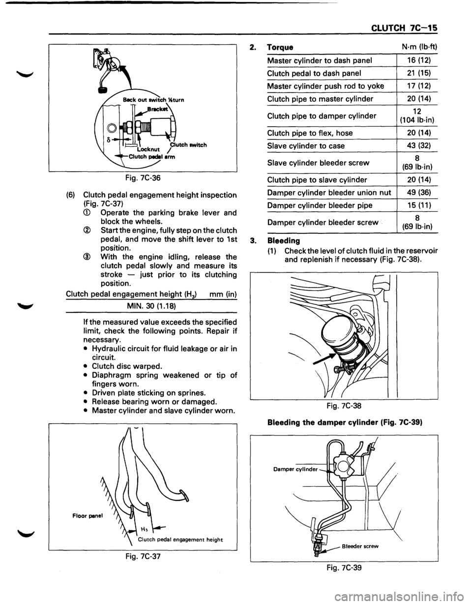
Fig. 7C-36
(6) Clutch pedal engagement height inspection
(Fig.
7C-37)
® Start the engine, fully step on the clutch
pedal,
and move the shift lever to 1st
position.
@ With the engine idling, release the
clutch pedal slowly and measure its
stroke -just prior
to its clutching
position.
Clutch pedal engagement height (H3) mm (in)
MIN. 30 (1.18)
If the
measured value exceeds the specified
limit, check the following points. Repair if
necessary.
• Hydraulic circuit for fluid leakage or air in
circuit.
• Clutch disc warped.
• Diaphragm spring weakened or tip of
fingers worn.
• Driven plate sticking on sprines.
• Release bearing worn or damaged.
• Master cylinder and slave cylinder worn.
Floor panel
Fig. 7C-37
CLUTCH 7C-15
2. Torque N·m (lb·ft)
Master cylinder to dash panel 16 (12)
Clutch pedal to dash panel 21 (15)
Master cylinder push rod to yoke 17 (12)
Clutch pipe to master cylinder 20 (14)
Clutch pipe
to damper cylinder 12
(104 lb·in)
Clutch
pipe to flex, hose 20 (14)
Slave cylinder to case 43 (32)
Slave
cylinder bleeder screw 8 (691b·in)
Clutch
pipe to slave cylinder 20 (14)
Damper cylinder bleeder union nut 49 (36)
Damper cylinder bleeder pipe 15 (11)
Damper cylinder
bleeder screw 8 (69 lb·in)
3. Bleeding
(1) Check
the level of clutch fluid in the reservoir
and
replenish if necessary (Fig. 7C-38).
Fig. 7C-38
Bleeding the damper cylinder (Fig. 7C-39)
Damper cylinder
Fig. 7C-39
Page 1150 of 1928
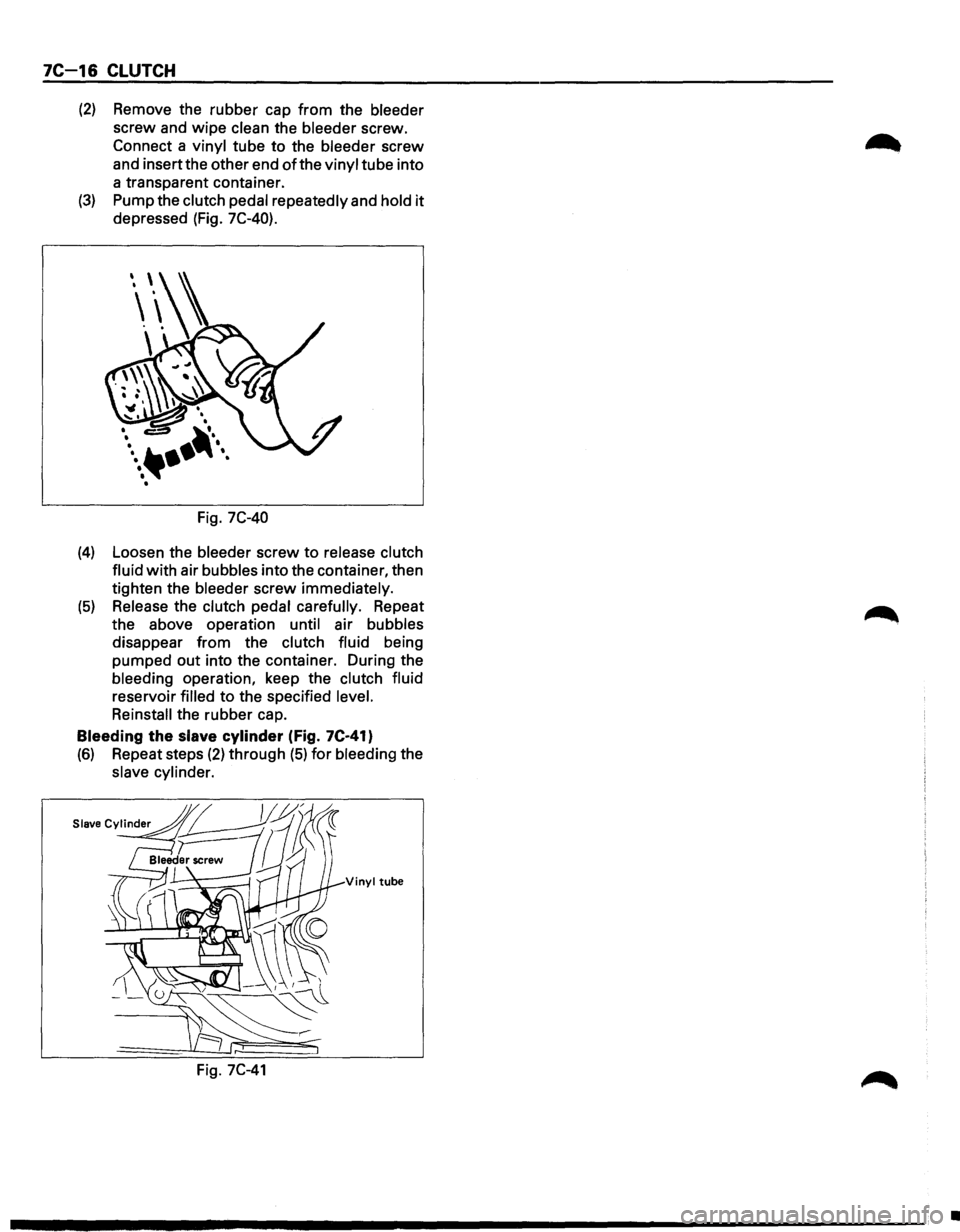
7C-16 CLUTCH
(2) Remove the rubber cap from the bleeder
screw and wipe clean the bleeder screw.
Connect a vinyl tube to the bleeder screw
and insertthe other end
of the vinyl tube into
a transparent container.
(3) Pump the clutch pedal repeatedly and hold it
depressed (Fig. 7C-40).
Fig. 7C-40
(4) Loosen the bleeder screw to release clutch
fluid with air bubbles into the container, then
tighten the bleeder screw immediately.
(5) Release the clutch pedal carefully. Repeat
the above operation until air bubbles
disappear from the clutch fluid being
pumped out into the container. During the
bleeding operation, keep the
clutch fluid
reservoir filled to the specified level.
Reinstall the rubber cap.
Bleeding
the slave cylinder (Fig. 7C·41)
(6) Repeat steps (2) through (5) for bleeding the
slave cylinder.
Vinyl tube
Fig. 7C-41
•
Page 1151 of 1928
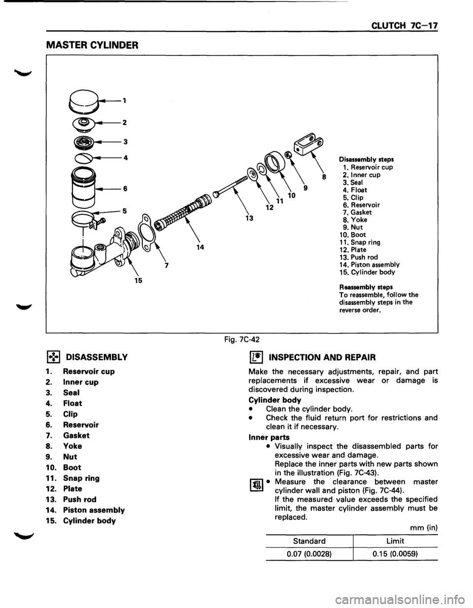
MASTER CYLINDER
l•!•l DISASSEMBLY
1. Reservoir cup
2. Inner cup
3. Seal
4. Float
5. Clip
6. Reservoir
7. Gasket
8. Yoke
9. Nut
10. Boot
11. Snap ring
12. Plate
13. Push rod
14. Piston assembly
15. Cylinder body
..........
Fig. 7C-42
CLUTCH 7C-17
Disassembly steps
1. Reservoir cup
2. Inner cup
3. Seal 4. Float 5. Clip 6. Reservoir 7. Gasket 8. Yoke 9. Nut 10. Boot
11. Snap ring
12. Plate
13. Push rod
14. Piston assembly
15. Cylinder
body
Reassembly steps To reassemble, follow the disassembly steps in the
reverse order.
IL•I INSPECTION AND REPAIR
Make the necessary adjustments, repair, and part
replacements
if excessive wear or damage is
discovered during inspection.
Cylinder body
• Clean the cylinder body.
• Check the fluid return port for restrictions and
clean
it if necessary.
Inner parts
• Visually inspect the disassembled parts for
excessive wear and damage.
Replace the inner parts
with new parts shown
in the
illustration (Fig. 7C-43).
ltil• Measure the clearance between master
cylinder
wall and piston (Fig. 7C-44).
If the measured value exceeds the specified
limit, the master cylinder assembly
must be
replaced.
mm (in)
Standard Limit
0.07
(0.0028) 0.15 (0.0059)
Page 1152 of 1928

7C-18 CLUTCH
Fig. 7C-43
Fig. 7C-44
SLAVE CYLINDER
~\
4
5
3
l•!•l REASSEMBLY
To reassemble, follow the disassembly steps in the
reverse
order, noting the following points:
1. Cylinder body
D • lmmHrse the cylinder body in clean brake fluid
L:::J (Fig. 7C-45).
2. Piston assembly
D Before installing, apply a thin coat of rubber
L:::J grease to the piston. Install cup in groove in
IE41 piston with the lip turned to front of cylinder.
Use care to prevent damaging the lip of the piston
seat.
Fig.
7C-45
Disassembly steps
1. Boot
2. Push rod
3. Piston and piston
cup 4. Spring
5. Cylinder body
Reassembly steps
To reassemble, follow the disassembly steps in the reverse order.
Fig. 7C-46
•
Page 1153 of 1928
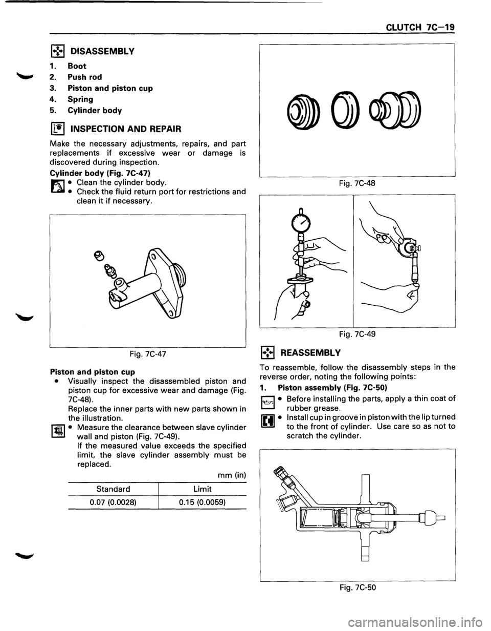
l.-!•1 DISASSEMBLY
1. Boot
2. Push rod
3. Piston and piston cup
4.
Spring
5. Cylinder body
IL•I INSPECTION AND REPAIR
Make the necessary adjustments, repairs, and part
replacements
if excessive wear or damage is
discovered during inspection.
Cylinder body (Fig. 7C-47)
E'1 • Clean the cylinder body.
Lal • Check the fluid return port for restrictions and
clean it if necessary.
Fig. 7C-47
Piston and piston cup
• Visually inspect the disassembled piston and
piston cup
for excessive wear and damage (Fig.
7C-48).
Replace the inner parts
with new parts shown in
the
illustration.
l'fil • Measure the clearance between slave cylinder
l.!!!l wall and piston (Fig. 7C-49).
If the measured value exceeds the specified
limit, the slave cylinder assembly
must be
replaced.
mm (in)
Standard Limit
0.07 (0.0028) 0.15 (0.0059)
Fig. 7C-48
Fig. 7C-49
l•!.-1 REASSEMBLY CLUTCH
7C-19
To
reassemble, follow the disassembly steps in the
reverse order, noting the
following points:
1. Piston assembly (Fig. 7C-50)
D • Before installing the parts, apply a thin coat of
L::::.l rubber grease.
0 • Install cup in groove in piston with the lip turned
U to the front of cylinder. Use care so as not to
scratch the cylinder.
Fig.
7C-50