ignition ISUZU TROOPER 1995 Workshop Manual
[x] Cancel search | Manufacturer: ISUZU, Model Year: 1995, Model line: TROOPER, Model: ISUZU TROOPER 1995Pages: 1928
Page 859 of 1928
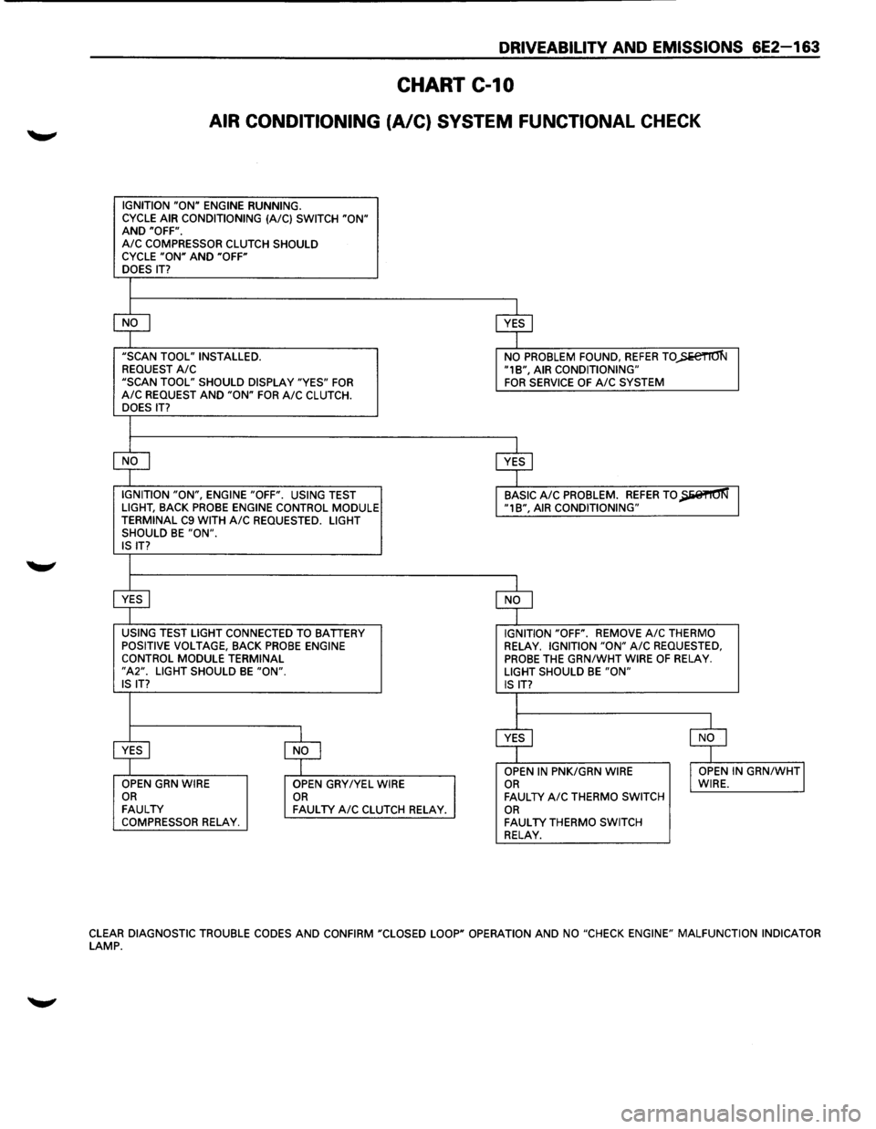
DRIVEABILITV AND EMISSIONS 6E2-163
CHART C-10
AIR CONDITIONING (A/C) SYSTEM FUNCTIONAL CHECK
IGNITION "ON" ENGINE RUNNING.
CYCLE AIR CONDITIONING (A/C) SWITCH "ON" AND "OFF". A/C COMPRESSOR CLUTCH SHOULD
CYCLE "ON" AND "OFF"
DOES IT?
$
$
"SCAN TOOL" INSTALLED.
NO PROBLEM FOUND, REFER TO)>e€TIO'N REQUEST A/C "1B", AIR CONDITIONING"
"SCAN TOOL" SHOULD DISPLAY "YES" FOR FOR SERVICE OF A/C SYSTEM A/C REQUEST AND "ON" FOR A/C CLUTCH.
DOES IT?
$
$
IGNITION "ON", ENGINE "OFF". USING TEST BASIC A/C PROBLEM. REFER TO~ LIGHT, BACK PROBE ENGINE CONTROL MODULE "1B", AIR CONDITIONING"
TERMINAL C9 WITH A/C REQUESTED. LIGHT
SHOULD BE "ON". IS IT?
$ $
USING TEST LIGHT CONNECTED TO BATTERY IGNITION "OFF". REMOVE A/C THERMO
POSITIVE VOLTAGE, BACK PROBE ENGINE RELAY. IGNITION "ON" A/C REQUESTED, CONTROL MODULE TERMINAL PROBE THE GRN/WHT WIRE OF RELAY. "A2". LIGHT SHOULD BE "ON". LIGHT SHOULD BE "ON" IS IT?
IS IT?
I
$ $
~ $ OPEN IN PNK/GRN WIRE I OPEN IN GRN/WHTJ OPEN GRN WIRE
OPEN GRY/YEL WIRE OR WIRE. OR OR FAULTY A/C THERMO SWITCH FAULTY FAULTY A/C CLUTCH RELAY. OR COMPRESSOR RELAY. FAULTY THERMO SWITCH RELAY.
CLEAR DIAGNOSTIC TROUBLE CODES AND CONFIRM "CLOSED LOOP" OPERATION AND NO "CHECK ENGINE" MALFUNCTION INDICATOR LAMP.
Page 876 of 1928
•
"'Tl c3' -..J )> I "'
~ )
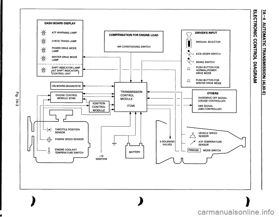
DASH
BOARD
DISPLA
V
*
*
*
*
ATF
WARNING
LAMP
CHECK
TRANS
LAMP
POWER DRIVE MODE LAMP WINTER DRIVE MODE LAMP
~----------------
SHIFT INDICATOR
LAMP
COMPENSATION
FOR
ENGINE
LOAD
AIR CONDITIONING SWITCH
TI
DRIVER'S
INPUT
liJ
MANUAL
SELECTOR
~
KICK-DOWN SWITCH
" ~
BRAKE
SWITCH
*
(AfT
SHIFT INDICATOR)
CONTROL
UNIT
---
' ---
I-------------,
il
PUSH BUTTON
FOR
NORMALJPOWER
DRIVE MODE
ON-BOARD DIAGNOSTIC
j4
.. ,
..
l__l--1 L_-$-L_g
ENGINE CONTROL
MODULE
(ECM)
_ IGNITION
CONTROL
I
MODULE
i
THROTTLE POSITION
SENSOR
ENGINE SPEED SENSOR
l
I
I -
ENGINE COOLANT TEMPERATU~,_.TCH
)
I +12 IGNITION
• •
TRANSMISSION
CONTROL MODULE
(TCM)
j
L I
BATTERY
)
--
~
'
5SOLENOID VALVES
il
-·----·
___.
u
PUSH BUTTON
FOR
WINTER DRIVE MODE
OTHERS
OVERDRIVE
OFF
SIGNAL
(CRUISE CONTROLLER)
ABS
SIGNAL
(ABS CONTROLLER)
f.-
n_
VEHICLE SPEED
SENSOR
f-
/
ATF TEMPERATURE SENSOR
L__ L__
[PRNDJ2L
I MODE SWITCH
-
m
.....
r-
)>
m
I
(")
..;=...
-t
)>
;::g 0
c:
2
-1
-
0
(")
s:
(")
~
0
-
2
n
-t
-1
;::g
:a
0
)> z
r-
en
c
s:
:;
(i)
C)
en
~
0 z
3:
-..;=... r-w 0 I !!!
)
Page 878 of 1928
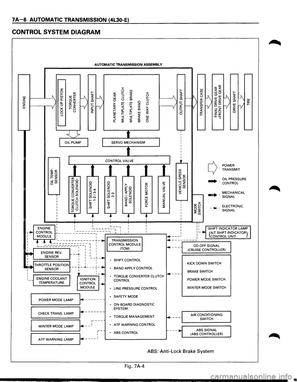
7A-6 AUTOMATIC TRANSMISSION (4L30-E)
CONTROL SYSTEM DIAGRAM
L1J ~ (!) z L1J
I
I
lr
t:··
~ .. I I
I
I
AUTOMATIC TRANSMISSION ASSEMBLY
O.:a: :Eo LLJ(J) t-z --' L1J oVl
ENGINE COOLANT TEMPERATURE
ffio ~---a:O wz >LLJ z--' oo uCJ> w::C :::>u at-a:=> ~d
0 0 z ... w, --'"' o-.. (J)N t-.!-u.. J: CJ)
IGNITION
CONTROL .
MODULE
~==PO=W==ER==M=O=D=E=L=A=M=P~r.-------
r-------CHECK TRANS. LAMP
~=W=IN=T=E=R=M=O=D=E=LA=M=P~~--J---
::c u L1J a: 1-:.:: ::c <( :::> <( u L1J --' a: 1-(!) u al :::> >-L1J L1J 0 --' 1-~ z u a: :5 <( ~ ~ --' al Cl.
Cl. L1J i=
i= L1J ~ z :.:: --' --' <( L1J :5 :::> :::> a: z Cl. ::!: ::!: al 0
0 a: L1J 0 >-0 > --'o --' z (l._ 1-<( L1J Cl.Q 0 > __,...,
SHIFT
CONTROL
BAND APPLY CONTROL
TORQUE CONVERTER CLUTCH CONTROL
LINE PRESSURE CONTROL
SAFETY MODE
ON-BOARD DIAGNOSTIC
SYSTEM
TORQUE MANAGEMENT
ATF WARNING CONTROL
r-ABS CONTROL
L--A-T_F_w_A_R_N_I_N_G_L_A_M_P_...Jr---_l 1---------------'
0 L1J "'a: Bio wVl __,z uw J:Vl L1J >
POWER c): TRANSMIT
.... : OIL PRESSURE
CONTROL
MECHANICAL
...• : SIGNAL
LLJJ: ou ELECTRONIC ot:: -•: ::!:~ SIGNAL
KICK DOWN SWITCH
BRAKE SWITCH
POWER MODE SWITCH
WINTER MODE SWITCH
AIR CONDITIONING
SWITCH
ABS
SIGNAL (ASS CONTROLLER)
ABS: Anti-Lock Brake System
Fig. 7A-4
..
Page 882 of 1928
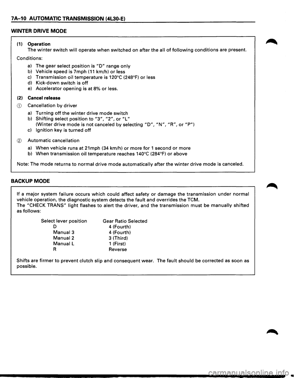
7A-10 AUTOMATIC TRANSMISSION (4L30-E)
WINTER DRIVE MODE
(1) Operation
The winter switch will operate when switched on after the all of following conditions are present.
Conditions:
a) The gear select position is "D" range only
b) Vehicle speed is 7mph (11 km/h) or less
c) Transmission oil temperature is 120°C (248°F) or less
d) Kick-down switch is off
e) Accelerator opening is at 8% or less.
(2) Cancel release
CD Cancellation by driver
a) Turning off the winter drive mode switch
b) Shifting select position to "3", "2", or "L"
(Winter drive mode is not canceled by selecting "D", "N", "R", or "P")
c) Ignition key is turned off
® Automatic cancellation
a) When vehicle runs at 21mph (34 km/h) or more for 1 second or more
b) When transmission oil temperature reaches 140°C (284°F) or above
Note: The mode returns
to normal drive mode automatically after the winter drive mode is canceled.
BACKUP MODE
If a major system failure occurs which could affect safety or damage the transmission under normal
vehicle operation, the diagnostic system detects the fault and overrides the TCM.
The "CHECK TRANS" light flashes to alert the driver, and the transmission must be manually shifted
as follows:
Select lever
position
D
Manual3
Manual2
Manual L
R
Gear Ratio Selected
4 (Fourth)
4 (Fourth)
3 (Third)
1 (First)
Reverse
Shifts are firmer to prevent clutch slip and consequent wear. The fault should be corrected as soon as
possible.
Page 883 of 1928

AUTOMATIC TRANSMISSION (4L30-E) 7 A-11
FUNCTIONS OF INPUT /OUTPUT COMPONENTS
Components Function
Speed sensor
Senses rotation
of output shaft and feeds the data to Transmission
(fixed
to transmission (T/M)) Control Module (TCM)
Throttle Senses the extent of throttle valve opening and the speed of the throttle
position sensor (TPS) valve lever motion to open the valve and feeds the data to TCM (fed to
(fixed to engine)
Engine Control Module (ECM) also)
I
Brake Switch (SW) Senses whether the driver has pressed the brake pedal or not and feeds
N (fixed
to brake pedal) the
information to TCM
p Kick-down SW (fixed to Senses whether the driver has pushed the accelerator pedal fully or not
u accelerator pedal) and feeds the information to TCM
T Mode
SW (fixed to T/M) Senses the select lever position and feeds the information to TCM
s Power drive SW Senses whether the driver has selected the power mode and feeds the
I (fixed to front console) information to TCM
G T/M
oil temp. sensor
Senses the T/M oil temperature and feeds the data to TCM
N Engine
coolant Senses the engine cooling water temperature and feeds the data to TCM
A temperature
SW (feeds the signal from ECM)
L
Engine speed
signal Feeds the signals monitoring engine speed to TCM from Ignition Control
Module
(fed to ECM also)
Air conditioning Senses whether the air conditioner has been switched on or not and
information feeds the information
to TCM
On-board diagnostic
input By monitoring the Ground (GND), the location of failure is shown on the
T/M
monitor lamp ("CHECK TRANS") by flashing the diagnostic trouble
code
Winter switch
Senses whether the driver has selected the winter mode, and feeds the
(fixed
to front console) information to TCM
Cruise
controller Downshift takes place when Overdrive OFF signal is received from auto
(Overdrive
OFF signal) cruise control unit
Shift
solenoid Selects shift point and gear position suited to the vehicle running con-s 1-2/3-4, 2-3
dition on the basis of TCM output 0 Band apply solenoid
Controls oil flow suited to the vehicle running condition on the basis of L
E TCM output
0 N
Torque
Converter Controls clutch engagement/disengagement suited to the vehicle
u 0 Clutch solenoid running condition on the basis of TCM output
T I Force motor Adjusts the oil pump delivery pressure to line pressure suited to the p D
(Pressure regulator vehicle running condition on the basis of TCM output u valve) T
Power drive mode lamp
Informs the driver whether the vehicle is in power mode or not
s Winter drive mode lamp Informs the driver whether the vehicle is in winter mode or not
I T/M monitor lamp Informs the driver of failure in the system. It also displays the self diagnosis
G
("CHECK TRANS") code.
N Data Link Connector
(DLC) When connected with TECH 1 or tester, can communicate the data for A
L function
check, etc. (fed to ECM also). When TECH 1 is not connected, can
communicate the
signal for torque management with ECM.
Self-diagnosis connector
When short-circuited with the bipolar connector, the T/M monitor lamp
displays
a failure by code.
ATF warning
lamp Lights when ATF oil temperature rises.
ABS signal When the select lever is at "Reverse" or "L" range, sends a signal to the
ABS controller as one of the ABS control conditions.
Page 894 of 1928
7 A-22 AUTOMATIC TRANSMISSION (4l30-E)
TEST DRIVING
Some 4L30-E automatic transmission complaints
vehicles will require a test drive as a part of the
diagnostic procedure.
Some codes will not set
unless the vehicle is moving. The purpose of the
test
drive is to duplicate the customer's complaint
condition and set a current Transmission Control
Module (TCM) trouble code. Perform this
procedure before each 4L30-E automatic trans
mission repair, and again after repairs are made.
IMPORTANT:
• Duplicate the condition under which the
customer's complaint was observed.
• Depending on the complaint, line pressure
gauge and the
TECH1 scan tool may be
required
during the test drive.
• During the test drive, it is important to record
all necessary data from the areas being
monitored, for use in diagnosis. Also listen for
and note any unusual noises.
The
following procedure should be used to test
drive 4L30-E automatic
transmission complaint
vehicles:
1. Turn the ignition ON without starting the
engine. Check
that the "CHECK TRANS" lamp
comes on for approximately 2 to 3 seconds
and then goes
out and remains out.
• If the lamp is flashing, GOTO CHECK
TRANS INDICATOR (on page 7A-46).
• If no serial data is present, see Chart 1:
DIAGNOSTIC CONNECTOR AND VOLTAGE
SUPPLY TEST (on page 7A-69 and 7A-70).
• If the lamp stays ON or stays OFF, GOTO
"CHECK TRANS"
CHECK (on page 7A-48).
NOTE:
Remember that, when TECH1 is connected,
line pressure will be at maximum during shifts.
2. Drive the vehicle. During the test drive be sure
that the transmission achieves normal
operating temperature (approx. 20 minutes) ..
Allow the transmission to go through all of 1ts
gear ranges, checking shift timing and
firmness.
Duplicate the owner's complaint
condition as closely as possible during the test
drive.
3. If, during the test drive, the "CHECK TRANS"
lamp comes on, use the TECH1 to check for
trouble codes.
4. If, during the test drive, a problem is felt, but
the "CHECK TRANS" lamp does not come on
and
no trouble codes are present, drive the
vehicle with the TCM disconnected (manually
shifting the vehicle).
•
In Manual L, the vehicle operates in first
gear.
• In Manual 2, the vehicle operates in third
gear.
• In Manual 3 or "D", the vehicle operates in
fourth gear.
If the problem still exists with the TCM
disconnected, refer
to the MECHANICAL/
HYDRAULIC DIAGNOSIS
in this Section.
5. If no problem has been found at this point,
check
all underhood connections that supply
power to the TCM and ignition fuses.
Physically and visually inspect all the TCM
harness connectors
for loose or corroded
terminals. Inspect the TCM ground points.
•
Page 917 of 1928
ELECTRONIC DIAGNOSIS
HOW TO DIAGNOSE THE PROBLEM
~ 1. To avoid incorrect diagnostics: this book needs
to be followed accurately. Unless stated: do
not jump
directly to a section that could
contain the solution: some important
information may be missed.
2. The sections in CAPITALS and bold are the
main sections that can be found in the
contents.
3. The GOTO "SECTION" means to continue to
check going to the "section".
4. The GOTHROUGH "SECTION" means to go
through the "section" and then to go back to
the place the GOTHROUGH was written.
5. BASIC ELECTRIC CIRCUITS:
You should understand the basic theory of
electricity. This will include the meaning of
voltage, amps, ohms, and what happens in a
circuit with an open or shorted wire. You
should also be able to read and understand
wiring diagrams.
6. IGNITION CYCLE:
When the car is driven a malfunction can occur
due to a car wiring harness problem, in this
case the driver can reset the system (as on a
personal computer). To reset the computer he
must: (
1) Stop the car and the engine.
(2) Turn the key ignition OFF.
(3) Turn the key ignition ON.
AUTOMATIC TRANSMISSION (4L30·E) 7 A-45
Page 918 of 1928
1 A-46 AUTOMATIC TRANSMISSION (4l30-E)
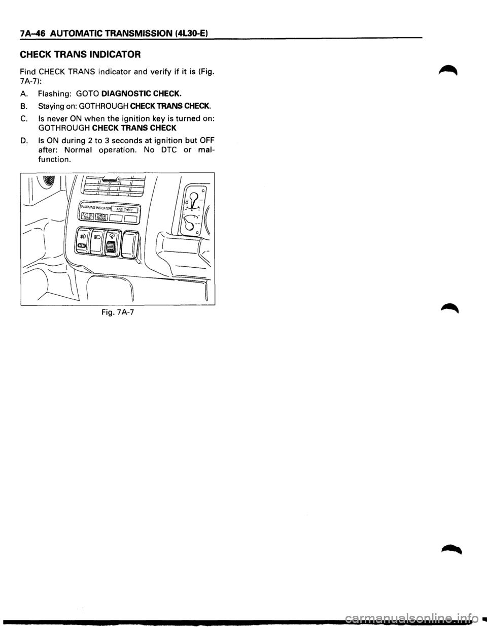
CHECK TRANS INDICATOR
Find CHECK TRANS indicator and verify if it is (Fig.
7A-7):
A.
Flashing: GOTO DIAGNOSTIC CHECK.
B. Staying on: GOTHROUGH CHECK TRANS CHECK.
C. Is never ON when the ignition key is turned on:
GOTHROUGH CHECK TRANS CHECK
D. Is ON during 2 to 3 seconds at ignition but OFF
after: Normal operation. No DTC or mal
function.
Fig. 7A-7
..
Page 919 of 1928
DIAGNOSTIC CHECK
This test determines if the transmission itself or its
~ inputs or outputs connections or sensors are failing.
IF you have a scan tool TECH1:
NO: Use the CHECK TRANS Indicator diagnostic
codes
GOTO FLASHING CODES.
YES:
1. Connect the TECH1: GOTHROUGH TECH1
CONNECTION.
2. Turn on the ignition but not the engine.
3. Push "F2" on TECH1 to see the Diagnostic
Trouble Code (OTC):
4. IF you have DTC?
YES: write down all code numbers and do the
DTCCHECK
NO: the DTC can not help you finding the
problem.
(1) GOTHROUGH "CHECK TRANS" CHECK
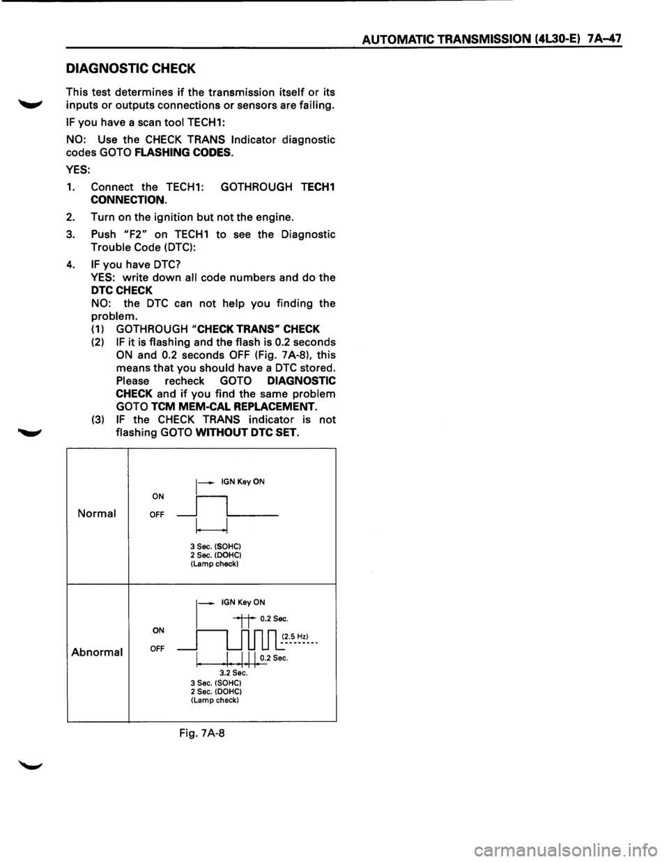
(2) IF it is flashing and the flash is 0.2 seconds
ON and 0.2 seconds OFF (Fig. 7A-8), this
means that you
should have a DTC stored.
Please recheck GOTO DIAGNOSTIC
CHECK and if you find the same problem
GOTO
TCM MEM-CAL REPLACEMENT.
(3) IF the CHECK TRANS indicator is not
........,. flashing GOTO WITHOUT DTC SET.
ON
~-IGNKeyON
__fL__ Normal OFF
w
3 Sec. (SOHC) 2 Sec. (DOHC} (Lamp check)
~-IGNKeyON
ON
~~ 0.2Sec.
~~~5-~=~--
Abnormal OFF
I. I Ill 0.2 Sec. I I I I I 3.2 Sec. 3 Sec. (SOHC) 2 Sec. (DOHC) (Lamp check}
Fig. 7A-8
AUTOMATIC TRANSMISSION (4L30-E) 7 A-47
Page 920 of 1928
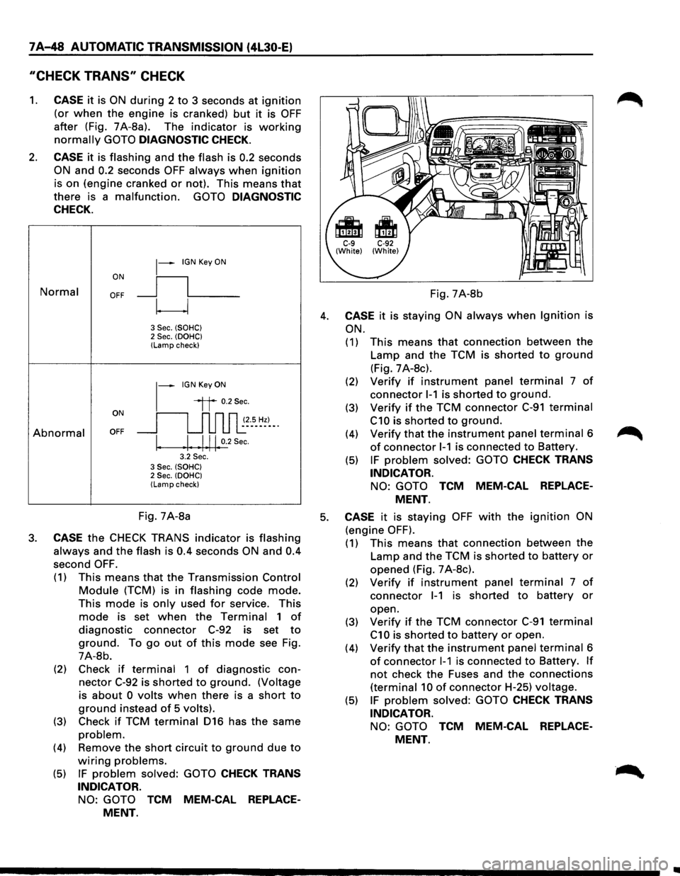
7 A-48 AUTOMATIC TRANSMISSION (4L30-E)
"CHECK TRANS" CHECK
1. CASE it is ON during 2 to 3 seconds at ignition
(or when the engine is cranked) but it is OFF
after (Fig. 7A-8a). The indicator is working
normally GOTO DIAGNOSTIC CHECK.
2. CASE it is flashing and the flash is 0.2 seconds
ON and 0.2 seconds OFF always when ignition
is on (engine cranked or not). This means that
there is a malfunction. GOTO DIAGNOSTIC
CHECK.
Normal
Abnormal
~-IGN Key ON
ON
II
OFF __j l___
~
3 Sec. (SOHC) 2 Sec. (OOHC) (Lamp check)
1-
IGN Key ON
il 0.2Sec.
oN 11 n n n ~~--s_ ~~)-_. OFF __j u u u l:
I. .I. .1.11. 0.2
Sec.
3.2 Sec. 3 Sec. (SOHC) 2 Sec. (OOHC) (Lamp check)
Fig. 7A-8b
4. CASE it is staying ON always when Ignition is
ON.
(1) This means that connection between the
Lamp and the TCM is shorted to ground
(Fig. 7 A-8c).
(2) Verify if instrument panel terminal 7 of
connector 1-1 is shorted to ground.
(3) Verify if the TCM connector C-91 terminal
C10 is shorted to ground.
(4) Verify that the instrument panel terminal 6
of connector 1-1 is connected to Battery.
(5) IF problem solved: GOTO CHECK TRANS
INDICATOR.
NO: GOTO TCM MEM-CAL REPLACE
MENT.
Fig. 7A-8a 5. CASE it is staying OFF with the ignition ON
(engine OFF). 3. CASE the CHECK TRANS indicator is flashing
always and the flash is 0.4 seconds ON and 0.4
second OFF.
(1) This means that the Transmission Control
Module (TCM) is in flashing code mode.
This mode is only used for service. This
mode is set when the Terminal 1 of
diagnostic connector C-92 is set to
ground. To go out of this mode see Fig.
7A-8b.
(2) Check
if terminal 1 of diagnostic con
nector C-92 is shorted to ground. (Voltage
is
about 0 volts when there is a short to
ground instead of 5 volts).
(3) Check if TCM terminal 016 has the same
problem.
(4) Remove the short circuit to ground due to
wiring problems.
(5) IF problem solved: GOTO CHECK TRANS
INDICATOR.
NO: GOTO TCM MEM-CAL REPLACE
MENT.
(1) This means that connection between the
Lamp and the TCM is shorted to battery or
opened (Fig. 7 A-8c).
(2) Verify if instrument panel terminal 7 of
connector 1-1 is shorted to battery or
open.
(3)
Verify if the TCM connector C-91 terminal
C1 0 is shorted to battery or open.
(4)
Verify that the instrument panel terminal 6
of connector 1-1 is connected to Battery. If
not check the Fuses and the connections
(terminal 10 of connector H-25) voltage.
(5) IF problem solved: GOTO CHECK TRANS
INDICATOR.
NO: GOTO TCM MEM-CAL REPLACE
MENT.