ECU ISUZU TROOPER 1995 User Guide
[x] Cancel search | Manufacturer: ISUZU, Model Year: 1995, Model line: TROOPER, Model: ISUZU TROOPER 1995Pages: 1928
Page 268 of 1928
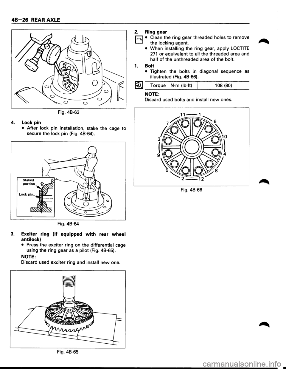
48-26 REAR AXLE
Fig. 48-63
4. Lock pin
• After lock pin installation, stake the cage to
secure the lock pin (Fig. 48-64).
Fig. 48-64
3. Exciter ring (If equipped with rear wheel
antilock)
• Press the exciter ring on the differential cage
using the ring gear
as a pilot (Fig. 48-65).
NOTE:
Discard used exciter ring and install new one.
Fig. 48-65
2. Ring gear
r;:::;J • Clean the ring gear threaded holes to remove
D the locking agent.
• When installing the ring gear, apply LOCTITE
271 or equivalent to all the threaded area and
half of the unthreaded area of the bolt.
1. Bolt
• Tighten the bolts in diagonal sequence as
illustrated (Fig. 48-66).
l~l Torque N·m (lb·ft) I 108 (80)
NOTE:
Discard used bolts and install new ones.
Fig. 48-66
Page 290 of 1928
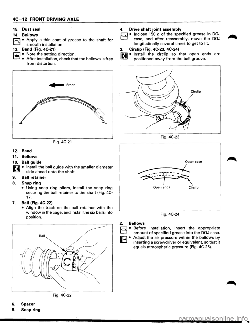
4C-12 FRONT DRIVING AXLE
15. Dust seal
14.
Bellows
c::::1 • Apply a thin coat of grease to the shaft for
D smooth installation.
13. Band (fig. 4C-21)
r=l • Note the setting direction.
'-=.1 • After installation, check that the bellows is free
from distortion.
12. Band
11.
Bellows
10. Ball
guide
~ Front
Fig. 4C-21
fiiil • Install the ball guide with the smaller diameter
U side ahead onto the shaft.
9. Ball retainer
8. Snap ring
• Using snap ring pliers, install the snap ring
securing the
ball retainer to the shaft (Fig. 4C-
17.
7. Ball (Fig. 4C-22)
• Align the track on the ball retainer with the
window in the cage, and install the six balls into
position.
Ball
Fig. 4C-22
6. Spacer
5. Snap ring
4. Drive shaft joint assembly
c::::1 • Inclose 150 g of the specified grease in DOJ
D case, and after reassembly, move the DOJ
longitudinally several
times to get to fit.
3. Circlip (Fig. 4C-23, 4C-24)
fiiil • Install the circlip so that open ends are
U positioned away from the ball groove.
Fig.
4C-23
Outer case
~-J.r~
Open ends Circlip
Fig. 4C-24
2. Bellows
c::::1 • Before installation, insert the appropriate
D amount of specified grease into the DOJ case.
m=J • Adjust the air pressure within the bellows by
I§C.I inserting a screwdriver or equivalent, so that it
equals atmospheric pressure (Fig. 4C-25).
1111
Page 304 of 1928
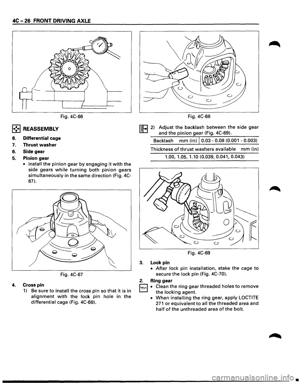
4C -26 FRONT DRIVING AXLE
l•!•l REASSEMBLY
8. Differential cage
7. Thrust washer
6. Side gear
5. Pinion gear
Fig. 4C-66
• Install the pinion gear by engaging it with the
side gears
while turning both pinion gears
simultaneously in the same direction (Fig. 4C-
67).
Fig. 4C-67
4. Cross pin
1) Be sure to install the cross pin so that it is in
alignment with the lock pin hole in the
differential cage (Fig. 4C-68). Fig.
4C-68
!EEl 2) Adjust the backlash between the side gear
and the
pinion gear (Fig. 4C-69).
Backlash
mm (in) I 0.03-0.08 (0.001 -0.003)
Thickness of thrust washers available mm (in)
1.00, 1.05, 1.10 (0.039, 0.041, 0.043)
Fig. 4C-69
3. Lock pin
• After lock pin installation, stake the cage to
secure the lock pin (Fig. 4C-70).
2. Ring gear
1~1 • Clean the ring gear threaded holes to remove
the locking agent.
• When installing the ring gear, apply LOCTITE
271 or equivalent to all the threaded area and
half of the unthreaded area of the bolt.
•
Page 420 of 1928
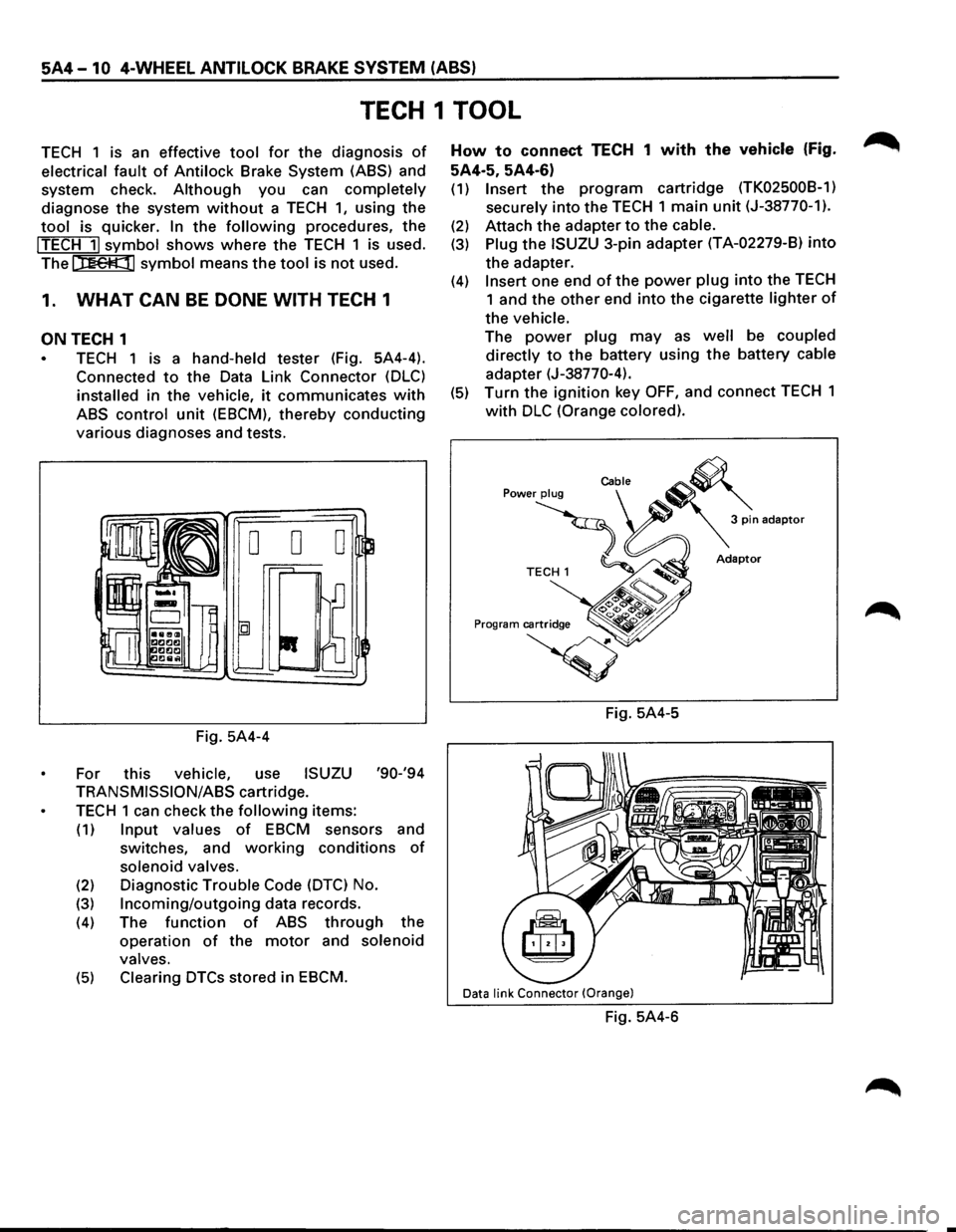
5A4-10 4-WHEEL ANTILOCK BRAKE SYSTEM (ABS)
TECH 1 TOOL
TECH 1 is an effective tool for the diagnosis of
electrical fault of Antilock Brake System (ASS) and
system check.
Although you can completely
diagnose the system without a TECH 1, using the
tool is quicker. In the following procedures, the
!TECH 11 symbol shows where the TECH 1 is used.
The
t::nettll symbol means the tool is not used.
1. WHAT CAN BE DONE WITH TECH 1
ON TECH 1
TECH 1 is a hand-held tester (Fig. 5A4-4).
Connected
to the Data Link Connector (DLC)
installed in the vehicle, it communicates with
ABS control unit (EBCM), thereby conducting
various diagnoses and tests.
Fig. 5A4-4
For this
vehicle, use ISUZU '90-'94
TRANSMISSION/ASS cartridge.
TECH 1 can check the following items:
(1) Input values of EBCM sensors and
switches, and
working conditions of
solenoid valves.
(2) Diagnostic Trouble Code (DTC) No.
(3) Incoming/outgoing data records.
(4) The function of ABS through the
operation
of the motor and solenoid
valves.
(5) Clearing DTCs stored in EBCM.
How to connect TECH 1 with the vehicle (Fig.
5A4·5, 5A4-6)
(1) Insert the program cartridge (TK02500B-1)
securely
into the TECH 1 main unit (J-38770-1).
(2) Attach the adapter to the cable.
(3) Plug the ISUZU 3-pin adapter (T A-02279-8) into
the adapter.
(4) Insert one end of the power plug into the TECH
1 and the other end into the cigarette lighter of
the vehicle.
The power plug may as well be coupled
directly
to the battery using the battery cable
adapter (J-38770-4).
(5) Turn the ignition key OFF, and connect TECH 1
with DLC (Orange colored).
Fig. 5A4-5
Data link Connector (Orange)
Fig. 5A4-6
Page 531 of 1928
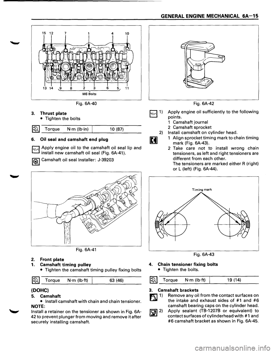
15 12 7 4 10
13 14 -.:9:...._--=8 __ =-2 ---..-....::3:.__ _ _:6:___:::..~5 11
M6 Bolts
Fig. 6A-40
3. Thrust plate
• Tighten the bolts
~~~ Torque N·m (lb·in) 10 (87)
6. Oil
seal and camshaft end plug
1~·1 Apply engine oil to the camshaft oil seal lip and
install new camshaft oil seal (Fig. 6A-41).
1®-1 Camshaft oil seal Installer: J-39203
Fig. 6A-41
2. Front plate
1. Camshaft timing pulley
• Tighten the camshaft timing pulley fixing bolts
1~1 Torque N·m (lb·ft) 63 (46)
(DOHC)
5. Camshaft
• Install camshaft with chain and chain tensioner.
NOTE:
Install a retainer on the tensioner as shown in Fig. 6A-
42 to prevent plunger from moving and remove it after
securely
installing camshaft.
GENERAL ENGINE MECHANICAL 6A-15
~1)
2)
u
Fig. 6A-42
Apply engine oil sufficiently to the following
points.
1 Camshaft journal
2 Camshaft sprocket
Install camshaft on cylinder head.
1 Align sprocket
timing mark to chain timing
mark (Fig. 6A-43).
2 Take care
not to install wrong chain
tensioners,
as left and right tensioners are
different from each other.
The tensioners are marked either R (right)
or L (left) (Fig. 6A-44).
Timing mark
Fig. 6A-43
4. Chain tensioner fixing bolts
• Tighten the bolts.
1~1 Torque N·m (lb·ft) 19 (14)
3. Camshaft brackets
m 1) Remove any oil from the contact surfaces on
Lll the intake and exhaust sides of #1 and #6
camshaft bearing caps on the cylinder head.
~~~2) Apply sealant (TB-12078 or equivalent) to
contact surfaces of cylinderhead with # 1 and
#6 camshaft bracket as shown in Fig. 6A-45.
Page 563 of 1928
4. Exhaust Gas Recirculation pipe and valve
• Tighten each fixing bolt to the specified torque.
Valve fixing bolt
1«1 Torque N·m (lb·in) 8 (69)
CYLINDER HEAD COVER RH (SOHC)
1
2
4
ENGINE (V6 3.2L DOHC AND SOHC) 6A1-5
Exhaust manifold fixing bolt
1«1 Torque N·m (lb·ft) I 28 (21)
3. Engine harness bracket
2. Positive Crankcase
Ventilation hose and
Vacuum hose
1. Ignition wire
3
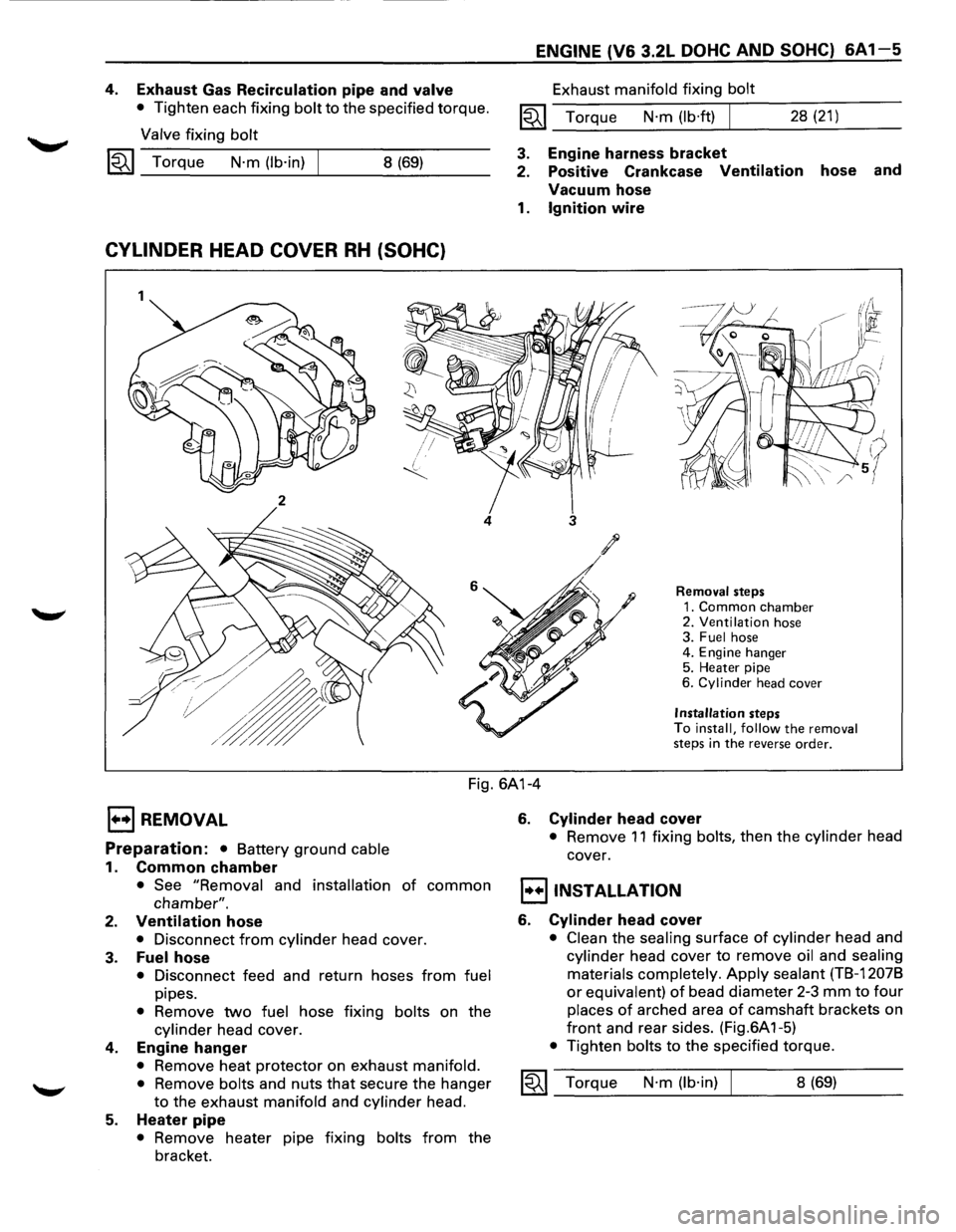
Removal steps
1. Common chamber 2. Ventilation hose
3. Fuel hose
4. Engine hanger
5. Heater pipe
6.
Cylinder head cover
Installation steps
To install, follow the removal
steps in the reverse order.
Fig. 6A1-4
EJ REMOVAL
Preparation: • Battery ground cable
1. Common chamber
• See "Removal and installation of common
chamber".
2. Ventilation hose
• Disconnect from cylinder head cover.
3. Fuel hose
• Disconnect feed and return hoses from fuel
pipes.
• Remove two fuel hose fixing bolts on the
cylinder head cover.
4. Engine hanger
• Remove heat protector on exhaust manifold.
•
Remove bolts and nuts that secure the hanger
to the exhaust manifold and cylinder head.
5. Heater pipe
• Remove heater pipe fixing bolts from the
bracket.
6. Cylinder head cover
• Remove 11 fixing bolts, then the cylinder head
cover.
I•+IINSTALLATION
6. Cylinder head cover
• Clean the sealing surface of cylinder head and
cylinder head cover to remove oil and sealing
materials completely.
Apply sealant (TB-12078
or equivalent) of bead diameter 2-3 mm to four
places of arched area of camshaft brackets on
front and rear sides. (Fig.6A 1-5)
• Tighten bolts to the specified torque.
1«1 Torque N·m (lb·in) 8 (69)
Page 571 of 1928
l·u·IINSTALLATION
16. Common chamber
• Tighten bolts and nuts to the specified torque.
Bolts
1«1 Torque N·m (lb·ft) 24 (17)
Nuts
1«1 Torque N·m (lb·ft) 24 (17)
15. Throttle body
• Connect the water hose securely.
14. Common chamber duct
• Tighten bolts and nuts to the specified torque.
Bolts
~ Torque N·m (lb·ft) 24 (17)
Nuts
~ Torque N·m (lb·ft) 24 (17)
13. Exhaust Gas Recirculation Valve assembly
• Tighten bolts to the specified torque.
Exhaust Gas Recirculation Valve
Side
1«1 Torque N·m (lb·in) I 8 (69)
Exhaust Manifold Side
1«1 Torque N·m (lb·ft) 28 (21)
12. Evaporative Emission Canister Purge hose
11. Positive Crankcase Ventilation hose
10. Fuel Pressure Control Valve vacuum hose
8. Throttle body
• Tighten bolts to the specified torque.
1«1 Torque N·m (lb·ft) I 19 (14)
9. Vacuum hose
• Connect vacuum hoses on canister Vacuum
Switching Valve and Exhaust Gas Recirculation
Vacuum
Switching Valve to the throttle body.
7. Ignition Control Module assembly
• Tighten bolts to the specified torque and
connect connector.
1«1 Torque N·m (lb·ft)
6. High tension cables
5. Connectors
• Connect each connector.
4. Vacuum booster hose
3. Canister vacuum hose
19 (14)
ENGINE (V6 3.2L DOHC AND SOHC) 6A 1-13
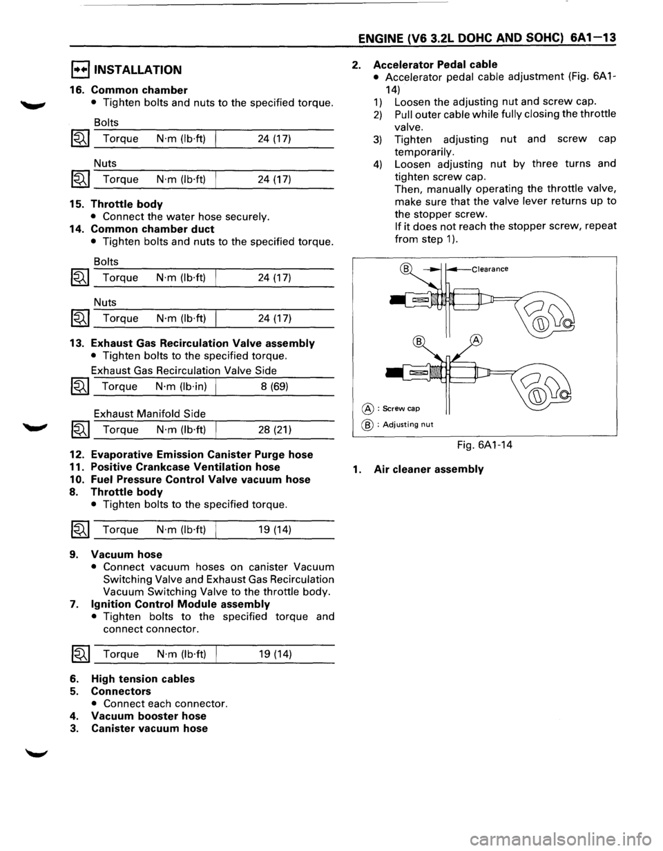
2. Accelerator Pedal cable
• Accelerator pedal cable adjustment (Fig. 6A 1-
14)
1) Loosen the adjusting nut and screw cap.
2) Pull outer cable while fully closing the throttle
valve.
3) Tighten adjusting nut and screw cap
temporarily.
4) Loosen adjusting nut by three turns and
tighten screw cap.
Then, manually operating the
throttle valve,
make sure that the valve lever returns up to
the stopper screw.
If it does not reach the stopper screw, repeat
from step 1 ).
@:Screw cap
@ : Adjusting nut
Fig. 6A1-14
1. Air cleaner assembly
Page 573 of 1928
16. Intake manifold
• Remove two fixing bolts and four nuts, then
remove the intake
manifold.
I••IINSTALLATION
16. Intake manifold
• Tighten bolts and nuts to the specified torque.
Bolts
~~~ Torque N·m (lb·ft) 24 (17)
Nuts
1~1 Torque N·m (lb·ft) 24 (17)
15. Connectors
• Connect each connector.
14. Fuel hoses
• Connect the hoses securely and install bolts on
the head cover.
13. Common chamber
• Tighten bolts and nuts to the specified torque.
Bolts
~~~ Torque N·m (lb·ft) 24 (17)
Nuts
~~~ Torque N·m (lb·ft) 24 (17)
12. Exhaust Gas Recirculation Valve assembly
• Tighten bolts to the specified torque.
~~~ Torque N·m (lb·in) I 9 (78)
11. Evaporative Emission Canister Purge hose
10. Fuel Pressure Control Valve vacuum hose
9. Positive Crankcase Ventilation hose
7. Throttle body
• Tighten bolts to the specified torque.
~~~ Torque N·m (lb·ft) I 22 (16)
8. Vacuum hose
• Connect vacuum hoses on canister Vacuum
Switching Valve and Exhaust Gas Recirculation
Vacuum
Switching Valve to the throttle body.
6. Ignition Control Module assembly
• Tighten bolts to the specified torque and
connect connector.
~~~ Torque N·m (lb·ft) 22 (16)
5. High tension cables
4. Connectors
• Connect each connector without fail.
3. Vacuum booster hose
ENGINE (V6 3.2L DOHC AND SOHC) 6A1-15
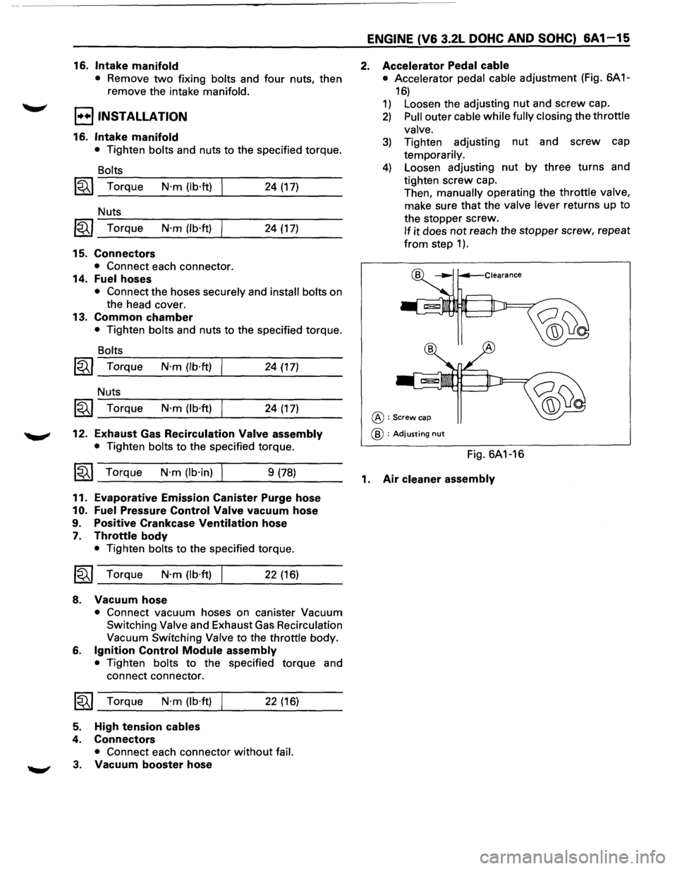
2. Accelerator Pedal cable
• Accelerator pedal cable adjustment (Fig. 6A 1-
16)
1) Loosen the adjusting nut and screw cap.
2) Pull outer cable while fully closing the throttle
valve.
3) Tighten adjusting nut and screw cap
temporarily.
4) Loosen adjusting nut by three turns and
tighten
screw cap.
Then,
manually operating the throttle valve,
make sure that the valve lever returns up to
the stopper screw.
If it does not reach the stopper screw, repeat
from step 1 ).
@:Screw cap
@ : Adjusting nut
Fig. 6A1-16
1. Air cleaner assembly
Page 575 of 1928
... t&:?
17. Fuel hoses
• Disconnect feed and return fuel hoses from fuel
pipes, and remove
two bracket fixing bolts on
the cylinder head cover.
18. Fuel injector connectors
• Disconnect from injectors.
19. Intake manifold
• Remove engine harness bracket on RH side.
• Remove two bolts and four nuts, and remove
intake manifold.
I••IINSTALLATION
19. Intake manifold
• Tighten bolts and nuts to the specified torque.
Bolts
~~~ Torque N·m (lb·ft) 24 (17)
Nuts
~~~ Torque N·m (lb·ft) 24 (17)
18. Fuel injector connectors
• Connect each connector.
17. Fuel hoses
• Connect the hoses securely and install the bolts
on the head cover.
16. Common chamber
• Tighten bolts and nuts to the specified torque.
Bolts
~ Torque N·m (lb·ft) 24 (17)
Nuts
~ Torque N·m (lb·ft) 24 (17)
15. Throttle body
• Connect surely the water hose.
14. Common chamber duct
• Tighten bolts and nuts to the specified torque.
Bolts
~ Torque N·m (lb·ft) 24 (17)
Nuts
~ Torque N·m (lb·ft) 24 (17)
13. Exhaust Gas Recirculation Valve assembly
• Tighten bolts to the specified torque.
Exhaust Gas Recirculation Valve
Side
~~~ Torque N·m (lb·in) I 8 (69)
Exhaust Manifold Side
~~~ Torque N·m (lb·ft) 28 (21)
12. Evaporative Emission Canister Purge hose
11. Positive Crankcase
Ventilation hose
10. Fuel Pressure Control Valve vacuum hose
ENGINE (V6 3.2L DOHC AND SOHC) 6A1-17
8. Throttle body
• Tighten bolts to the specified torque.
~~~ Torque N·m (lb·ft) I 19 (14)
9. Vacuum hose
• Connect vacuum hoses on canister Vacuum
Switching Valve and Exhaust Gas Recirculation
Vacuum Switching Valve
to the throttle body.
7. Ignition Control Module assembly
• Tighten bolts to the specified torque and
connect connector.
~~~ Torque N·m (lb·ft) 19 (14)
6. High tension cables
5. Connectors
• Connect each connector without fail.
4. Vacuum booster hose
3. Canister vacuum hose
2. Accelerator Pedal cable
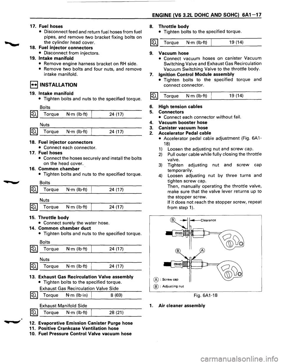
• Accelerator pedal cable adjustment (Fig. 6A 1-
18)
1) Loosen the adjusting nut and screw cap.
2) Pull outer cable while fully closing the throttle
valve.
3) Tighten adjusting nut and screw cap
temporarily.
4) Loosen adjusting nut by three turns and
tighten screw cap .
Then, manually operating the throttle valve,
make sure
that the valve lever returns up to
the stopper screw.
If it does not reach the stopper screw, repeat
from step 1 ).
@:Screw cap
@ : Adjusting nut
Fig. 6A1-18
1. Air cleaner assembly
Page 577 of 1928
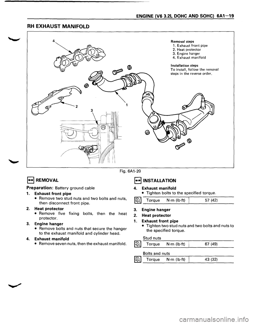
RH EXHAUST MANIFOLD
4
ENGINE (V6 3.2L DOHC AND SOHC) 6A1-19
Removal steps
1.
Exhaust front pipe 2. Heat protector 3. Engine hanger
4. Exhaust manifold
Installation
steps To install, follow the removal steps in the reverse order.
1••1 REMOVAL
Fig. 6A1-20
I••IINSTALLATION
Preparation: Battery ground cable
1. Exhaust front pipe
• Remove two stud nuts and two bolts and nuts,
then disconnect front pipe.
2. Heat protector
• Remove five fixing bolts, then the heat
protector.
3. Engine hanger
• Remove bolts and nuts that secure the hanger
to the exhaust manifold and cylinder head.
4. Exhaust manifold
• Remove seven nuts, then the exhaust manifold.
4. Exhaust manifold
• Tighten bolts to the specified torque.
I~I_T_or.:....q:....u_e __ N_·m__:_(l_b·_ft.:....) _!._ ___ 5_7_(4_2_) __ _
3.
2.
1.
Engine hanger
Heat protector
Exhaust front pipe
• Tighten two stud nuts and two bolts and nuts to
the specified torque.
Stud nuts
~~~ Torque N·m (lb·ft) 67 (49)
Bolts and nuts
~~~ Torque N·m (lb·ft) 43 (32)